Applying the Forest Service Outdoor Recreation Accessibility Guidelines
The first step in applying Forest Service Outdoor Recreation Accessibility Guidelines (FSORAG) is to know when and where compliance is required. Section 1.0 "Application" states that newly constructed and altered camping facilities, picnic areas, constructed features, beach access routes, and outdoor recreation access routes under Forest Service jurisdiction must comply with FSORAG. When we build something, we need to build it for everybody (figure 33). FSORAG, however, doesn't require the installation of any particular feature. For example, if we build a raised tent platform, it must comply with FSORAG requirements, but FSORAG doesn't require providing raised tent platforms.
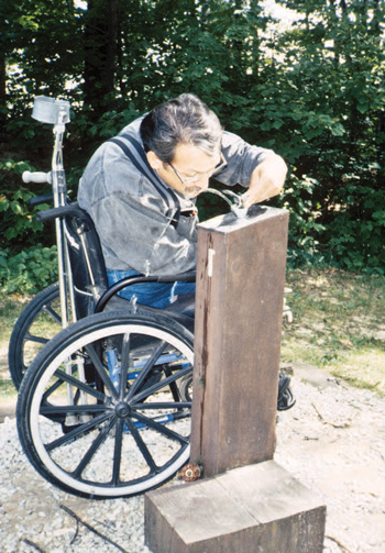
Figure 33— This water fountain works for most people.
Using the Conditions for an Exception in FSORAG
FSORAG is based on the realities of the outdoor environment. It recognizes that accessibility isn't possible everywhere because of the limitations imposed by natural terrain, existing vegetation, or other constraints. To ensure that the unique characteristics of the outdoor environment and recreation opportunity at a site aren't compromised or fundamentally altered, FSORAG section 1.1 requires achieving compliance with the technical accessibility requirements only to the extent practicable where certain circumstances (conditions for an exception) apply. These conditions apply only where an exception is specifically allowed in the technical requirement sections for a particular recreation feature.
Budget Tip
Extra cost is not an excuse.
If making a new or renovated recreation area accessible adds to the cost, the increase cannot be seen as an "undue financial burden."
When a Federal agency, such as the Forest Service, is funding a project, cost cannot be used as the reason for failing to make the project accessible, unless the cost of doing the work required by the accessibility guidelines would have a significant adverse impact on the agency's entire budget.
Conditions for an exception are not a blanket exemption from the technical requirements. Thoroughly explore all other design options that comply with the technical requirements and maintain the nature of the setting and experience before using deviations. When one or more of the following conditions for an exception exists in an outdoor recreation area, you may use a deviation from a specific technical requirement, but only where that condition exists. If that condition exists only on part of the feature or location, the technical requirement must be met for the rest of the feature or location. All the other technical requirements that are not affected by the condition for an exception still apply as well.
The following four conditions allow for deviations from specific technical requirements where exceptions are provided in the guidelines. Examples are provided to explain the intent of the conditions for each exception.
Condition for an Exception 1: Where compliance with the technical requirement is not practicable due to terrain
The phrase "is not practicable" in this condition for exception refers to something that isn't reasonable, rather than to something that is technically not possible. The intent of this condition is that the effort and resources required to comply shouldn't be disproportionately high relative to the level of access established.
Condition for an Exception 2: Where compliance with the technical requirement cannot be accomplished with the prevailing construction practices.
This condition for an exception may apply where construction methods that would be needed to comply with a technical requirement would require the use of equipment or methods other than those typically used in that setting. For instance, in an area where small equipment is normally used to minimize impact on a sensitive adjacent stream, blasting might be necessary to remove a rock outcrop to meet the technical requirement for width of an outdoor recreation access route. Because blasting typically would not be used in this situation, this condition for an exception would apply. If the work could be done using small equipment, the condition for an exception wouldn't apply.
Terminology Tip
What's practicable?
Using heavy construction equipment may make it possible to provide an outdoor recreation access route that is in compliance with the technical requirements for running slope in an area of steep terrain. However, extensive cuts or fills may be required, and that would cause drainage and erosion problems in highly susceptible soils. If compliance with the technical requirements would require building something that would be difficult, if not impossible, to construct or maintain properly, it is not practicable.
Design Tip
Determine where the conditions for an exception apply.
The following provides a good example of how designers may decide where a condition for an exception applies and where it might not. A renovation project at San Antonio Campground in the Santa Fe National Forest in the Southwestern Region includes a walk-in camping unit where a portion of the outdoor recreation access route is located on extremely steep ground, and there's no way to relocate the route to flatter land. The terrain makes it impossible to meet the technical requirement for running slope without severe cuts or fills.
Using the definitions in Forest Service Outdoor Recreation Accessibility Guidelines (FSORAG), the project is an alteration. Section 2.1 General Exception 2 of FSORAG allows a deviation from the slope requirement at existing recreation sites that are being altered, where a condition for an exception exists. A review of section 1.1 "Conditions for an Exception From the Technical Requirements" indicates that Condition for an Exception 1 applies to the section of the outdoor recreation access route that is on steep ground because compliance with the technical requirement for slope (grade) is not practicable due to terrain.
A deviation from the running slope requirement is permitted for the steep section of the outdoor recreation access route. However, all other technical requirements for the route, such as width, surfacing, and cross slope, must be met. Where the terrain is flatter and the cuts and fills aren't an issue, the technical provision for slope must be met. The exception to the slope requirement for the outdoor recreation access route to this particular walk-in campsite doesn't apply to other campsites at this campground. The outdoor recreation access route to each campsite must be examined individually to determine if a condition exists that would permit an exception to any requirement.
This condition for an exception isn't intended to exempt an area from the technical requirements simply because of a preferred construction practice. A contractor may prefer to use a large mechanical roller for efficiency rather than a smaller vibrating plate or impact-type compactor. A contractor's or designer's preference for the larger equipment doesn't by itself trigger the condition for an exception. A deviation from a specific technical requirement only is allowed if the equipment is essential to complete construction and if the work cannot be completed using the prevailing construction practices from similar locations.
Condition for an Exception 3: Where compliance with the technical requirement would fundamentally alter the function or purpose of the facility or the setting.
Public lands provide a wide variety of recreational settings, from highly developed campgrounds with plenty of opportunities for relaxing with family and friends to wilderness areas that provide opportunities to experience primitive and challenging conditions (figure 34). FSORAG recognizes the value of a wide array of recreation opportunities by allowing deviations from the technical requirements when compliance would unacceptably change the nature of recreation opportunities or conflict with the land and resource management plan for the area.
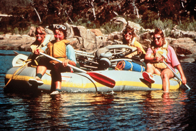
Figure 34—People like these rafters who recreate in primitive areas may be looking for challenge.
Design Tip
Look at the full range of issues.
Designers and managers need to examine the larger context and intent of the project to determine whether this condition for exception applies. Consider the full range of management and design issues during planning and continue throughout all stages of design development.
Consider existing and desired levels of development and site modification as identified in ROS classifications, visitor expectations, customer service, and so forth. Take into account how the site will be used. Will it be a jumping off point to a wilderness area where campers bring lightweight, compact equipment? Will it be a social gathering place where visitors bring a good portion of their worldly possessions and expect to have a place to set them up?
This condition for an exception would apply differently for a setting that has little or no human-influenced modifications than for a setting that has already been moderately or heavily modified, such as a highly developed recreation site.
Campers in a primitive setting experience the outdoor environment in a nearly natural state. These campers generally desire more challenge so they can rely on their outdoor survival skills. Manufactured building materials or engineered construction techniques that are used to comply with accessibility requirements could change the natural or undeveloped nature of the setting. You are not required to change the character of the setting and, therefore, change the nature of the recreation opportunity itself solely for the purpose of accessibility.
Condition for an Exception 4. Where compliance is precluded because the cultural, historic, or significant natural features are protected or are eligible for protection under Federal, State, or local law by:
-
Endangered Species Act (16 U.S.C. 1531 et seq.)
-
National Environmental Policy Act (42 U.S.C. 4321 et seq.)
-
National Historic Preservation Act (16 U.S.C. 470 et seq.)
-
Wilderness Act (16 U.S.C. 1131 et seq.)
-
Other Federal, State, or local laws that preserve threatened or endangered species, the environment, or archaeological, cultural, historical, or other significant natural features
Cultural features include archeological sites such as burial grounds and cemeteries, traditional cultural properties, tribal protected sites, and other properties considered sacred by an organized religion. Historic features are properties listed or eligible for listing on the National Register of Historic Places or other places of recognized historic value. Significant natural features are objects such as a large boulder or rocky outcrop, body of water, or unique vegetation that are regarded as distinctive or important locally, regionally, or nationally and, therefore, have been placed under legal protection (figure 35). This includes wilderness areas designated by Congress and areas protected under Federal or State laws, such as habitat for threatened or endangered species or designated wetlands.
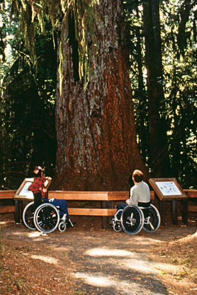
Figure 35—Properly developed recreation features don't harm unique vegetation; ancient trees are carefully protected.
Design Tip
Determine the extent of impact.
Only consider the additional impact of increasing the size, relocating the recreation feature, or implementing other changes to provide accessibility. For example, a proposed campsite may require that a number of trees of an uncommon species be removed. Removal would cause substantial harm to the tree grove. This condition for exception wouldn't apply if 15 trees must be removed to make way for a campsite that is not accessible and only three more trees must be removed to provide for one that is. The majority of the proposed damage to the grove is due to construction of the campsite, not due to compliance with accessibility requirements. In this case, an alternate location should be selected for the campsite.
Examples of situations in which this exception may apply include:
-
In wilderness areas designated by Congress, if work necessary to comply with a technical requirement can't be accomplished using handtools (use of mechanized equipment is prohibited by law)
-
Areas where imported materials, such as soil stabilizers, are prohibited to maintain the integrity of the natural ecosystem or historic resources
-
Designated wetlands or coastal areas where construction methods and materials are strictly limited
-
Tribal sacred sites where the undisturbed physical condition of the land is an important part of the sacred observance
-
Areas where water crossings are restricted to safeguard aquatic features or species protected under Federal or State laws
Documenting Exceptions
Recording and retaining documentation of determinations of the basis for exceptions for any outdoor recreation feature is a good practice. These records will become very valuable accounts of decisions and rationale when future changes are required or the public inquires about conditions.
Documentation is especially important for exceptions taken due to Condition 4. Federal laws and applicable State or local laws specified in Condition 4 prescribe certain activities or require certain analyses or procedures to be followed when planning to construct or alter facilities that may affect the cultural, historic, or natural features or species protected by that law. When work necessary to meet the technical requirements would directly or indirectly substantially harm the protected aspect, document the reason for the determination and then apply the exception. The documentation also may need to be included in the analysis or procedure records if required by specific laws.
Documentation of the basis for exceptions is required only when a condition for an exception prohibits full compliance with technical requirements on a portion of a trail or beach access route. An explanation of the condition that resulted in the determination that full compliance could not be achieved, the date the decision was made, and the name of the individuals who made the decision must be recorded and the documentation must be retained with the records for the construction or alteration project.
For trails or beach access routes only, if the entire trail or route must be exempted from the technical requirements because extreme or numerous conditions for exemptions make it impractical to provide a trail or route that meets the requirements, documentation must be sent to the U.S. Access Board. More information about this requirement is available in "Notifying the U.S. Access Board About Exemptions" and in "Documenting Exceptions and Notifying the U.S. Access Board About Exemptions" of this guidebook. Contact information for the U.S. Access Board is available at http://www.access-board.gov.
Getting From Here to There—Outdoor Recreation Access Routes
Providing accessibility in developed areas requires that people be able to get to features intended for public use. Outdoor recreation access routes are pedestrian routes that allow almost everybody to move around in a recreation area independently. Section 1.2 of FSORAG defines an outdoor recreation access route as "a continuous, unobstructed path designed for pedestrian use that connects constructed features in a campground, camping unit, picnic area, trailhead, or other recreation site where modifications are provided for visitor convenience and comfort." Figure 36 shows an outdoor recreation access route connecting a parking lot and scenic overlook. Section 2.0 of FSORAG contains the technical requirements for outdoor recreation access routes.
Outdoor recreation access routes are not required when camping facilities, picnic facilities, viewing areas, or outdoor constructed features are provided on trails. The routes connecting those facilities are to comply with the technical requirements for trails.
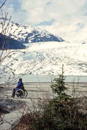
Figure 36—All people must be able to get from the parking area to the viewing area for the Mendenhall Glacier in Alaska; the same is true for other recreation sites in the National Forest System.
Outdoor recreation access routes ensure that visitors can move independently from their car or their camping or picnic spot to the other constructed features provided at a recreation area. When individual elements or constructed features are altered or replaced at existing recreation areas, Forest Service policy requires that they be accessible. However, if the ground under the element isn't changed as part of that renovation or replacement project, this work doesn't trigger the requirement for outdoor recreation access routes.
Design outdoor recreation access routes to meet technical requirements for running and cross slopes, resting intervals, surface, clear tread width, passing spaces, tread obstacles, protruding objects, and openings. If a condition for an exception prevents full compliance with a specific technical requirement on a portion of an outdoor recreation access route that is part of an alteration project, that portion of the outdoor recreation access route only has to comply with the specific technical requirements to the extent practicable. This deviation is not allowed for new construction; outdoor recreation access routes are required. When planning for a new outdoor recreation area or viewing area, the natural terrain and the general accessibility of the natural environment should be part of the site selection criteria.
Because individuals usually arrive at recreational vehicle (RV) dump stations by vehicle, there is an exception to the outdoor recreation access route connection requirement. A connecting outdoor recreation access route isn't required if an accessible vehicle pullup [sic] space is provided at the RV dump station.
The outdoor recreation access route may be provided within a roadway if the roadway is the only general circulation path for pedestrians at a recreation site. The outdoor recreation access route in the roadway isn't required to comply with outdoor recreation access route technical requirements for grade, resting, or passing intervals, but clear passage of 32 inches is required around or through speed restriction devices, gates, or other barriers.
Surfaces for Outdoor Recreation Access Routes
The surface of an outdoor recreation access route and the surface surrounding constructed features must be firm and stable. No exceptions are allowed. Slip resistance is not required because leaves and needles, dirt, ice, snow, and other surface debris and weather conditions are components of the natural environment and would be difficult, if not impossible, to avoid.
-
A firm surface resists deformation by indentations.
-
A stable surface is not permanently affected by expected weather conditions and can sustain normal wear and tear from the expected use(s) of the area between planned maintenance cycles.
Firm and stable surfaces prevent assistive devices from sinking into the surface. Surfaces that are not firm and stable make travel difficult for a person using crutches, a cane, a wheelchair, or other assistive device. In the accessibility guidelines, the standard assistive device is the wheelchair because its dimensions, multiple moving surface contact points and four wheels often are difficult to accommodate. If a person using a wheelchair can use an area, most other people also can use that area.
During the planning process, potential surface materials should be evaluated for noticeable distortion or compression during the season(s) of managed use and for stability under normal weather conditions and expected uses. If the surface won't remain firm and stable, another surface material should be used.
If the natural soils won't provide a firm and stable surface, soil stabilizer or artificial surfacing will be needed. The Forest Service technology and development report, "Soil Stabilizers on Universally Accessible Trails," contains information about the effectiveness of soil stabilizers. It is available at http://www.fs.fed.us/eng/pubs/pdf/00231202.pdf or http://www.fhwa.dot.gov/environment/fspubs/00231202/.
Design Tip
Use a rule of thumb to estimate firmness and stability.
What sort of surface is firm and stable? If the answer to both of the following questions is yes, the surface is probably firm and stable.
Could a person ride a narrow-tired bicycle across the surface easily without making imprints? (Bicycle tires are similar to the large rear wheels of a wheelchair.)
Could a folding stroller with small, narrow plastic wheels containing a 3-year-old be pushed easily across the surface without making imprints? (A stroller's wheels are similar to the front wheels of a wheelchair.)
While this method for determining firmness and stability isn't scientifically accurate, it has proven to be effective.
Design Tip
Provide appropriate walking surfaces for the setting.
A firm and stable surface does not always mean concrete and asphalt. The provision states that surface material should be appropriate to the setting and level of development. Some natural soils can be compacted so they are firm and stable. Other soils can be treated with stabilizers without drastically changing their appearance. Many surface materials that appear natural and that meet the firm and stable requirements also are available on the market. Investigate these options and use surface materials that are consistent with the site's level of development and that require as little maintenance as possible.
Construction Tip
Use better surface materials.
Generally, the following materials are more likely to provide firm and stable surfaces:
-
Crushed rock (rather than uncrushed gravel)
-
Rock with broken faces (rather than rounded rocks)
-
A rock mixture containing a full spectrum of sieve sizes, including fine material (rather than a single size)
-
Hard rock (rather than soft rock that breaks down easily)
-
Rock that passes through a ½-inch (13-millimeter) screen (rather than larger rocks)
-
Rock material that has been compacted into 3- to 4-inch (75- to 100-millimeter) -thick layers (rather than thicker layers)
-
Material that is moist (not soggy) before it is compacted (rather than material that is compacted when it is dry)
-
Material that is compacted with a vibrating plate compactor, roller, or by hand tamping (rather than material that is laid loose and compacted by use)
Slopes and Resting Intervals for Outdoor Recreation Access Routes
Running slope is the lengthwise slope of an outdoor recreation access route, parallel to the direction of travel. Outdoor recreation access route sections of any length may have a running slope ratio of up to 1:20, a 5-percent grade (figure 37). Steeper terrain may make this difficult to achieve. Many visitors can negotiate steeper slopes for short distances, so short segments of outdoor recreation access routes may be steeper, as shown in table 2, but the slope of an outdoor recreation access route may never exceed 1:10, a 10-percent grade. In this guidebook, the terms running slope and grade often are used interchangeably.
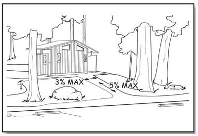
Figure 37—The basic slope requirements for outdoor recreation access routes and beach access routes.
Cross slopes—the side-to-side slope of an outdoor recreation access route—must not exceed 1:33 (3 percent), as shown by figure 37. However, if the surface of the outdoor recreation access route is paved or built with boards, the cross slope must not be steeper than 1:48 (2 percent).
Design Tip
The cross slope requirement depends on what material is used.
Those who use a mobility device know that as cross slope increases, travel becomes more difficult. This is because working against the sideways pull of the cross slope can double the effort needed to make forward progress. However, in an outdoor environment, the cross slope has to be steep enough that water won't accumulate on the travel surface. While slope and drainage can be precisely controlled on surfaces that are paved (asphalt, concrete, paving blocks, and so forth) or built with boards (wood planks, heavy timber, concrete, fiberglass, or other manufactured material), it's more difficult to ensure drainage on natural or gravel surfaces. When water accumulates on natural or gravel surfaces, they often become muddy and impassible. That's why the cross slope is allowed to be steeper on natural or gravel surfaces than on surfaces that are paved or built with boards.
Resting intervals are relatively level areas that provide an opportunity for people to catch their breath before continuing along the outdoor recreation access route. These intervals are required between each outdoor recreation access route segment any time the running slope ratio exceeds 1:20 (5 percent) as shown on table 2. A resting interval must be at least 60 inches (1,525 millimeters) long and at least as wide as the widest segment of the outdoor recreation access route leading into it, if the resting interval is within the outdoor recreation access route. If the resting interval is beside the outdoor recreation access route, it has to be at least 60 inches (1,525 millimeters) long and at least 36 inches (915 millimeters) wide. Depending on the design and location, the intersection of two outdoor recreation access routes may act as a resting interval.
| Runnign [sic] Slopes on ORARs | Maximum Length of Segment Between Resting Intervals | |
|---|---|---|
| Steeper than | But not Steeper than | |
| 1:20 (5 percent) | 1:12 (8.33 percent) | 50 feet (15 meters) |
| 1:12 (8.33 percent) | 1:10 (10 percent) | 30 feet (9 meters) |
Construction Tip
Slope and grade terminology.
Slopes are often described as a ratio of vertical distance to horizontal distance, or rise to run. For instance, a slope ratio of 1:20 means that for every 1 foot of vertical rise, there are 20 feet of horizontal distance; for every meter of vertical rise, there are 20 meters of horizontal distance (figure 38). When the slope ratio is stated as a percent, it is referred to as the grade. A 1:20 slope stated as a percent would be a 5 percent grade.
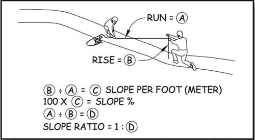
Figure 38—Determining the slope ratio.
The slopes of a resting interval may not exceed a ratio of 1:33 (3 percent) in any direction (figure 39). However, if the surface is paved or is built with boards, the slope can't be steeper than 1:48 (2 percent) in any direction.
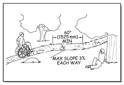
Figure 39—The basic resting interval requirements for outdoor recreation access routes.
Grade requirements for an outdoor recreation access route may be more difficult to meet when altering an existing site than during new construction. Accessibility was seldom considered when older recreation sites were designed. Many campgrounds and picnic areas were located in spectacularly scenic settings, but on steep terrain. Complying with the grade requirement in these areas may be difficult without a fundamental change to the recreation environment. A deviation is allowed for alteration projects where a condition for an exception exists.
In alterations only, if a condition for an exception prevents full compliance with a specific technical requirement on a portion of an outdoor recreation access route at camping and picnic facilities and at trailheads, that portion of the outdoor recreation access route is required to comply with the specific technical requirement only to the extent practicable.
This deviation from the technical requirement is not allowed to be used for new construction at camping and picnic facilities or at trailheads. When planning for a new outdoor recreation area, the natural terrain and the general accessibility of the natural environment should be part of the site selection criteria because compliance with outdoor recreation access route requirements is required for new construction.
Clear Tread Width and Passing Spaces for Outdoor Recreation Access Routes
Clear tread width means the width of the traveled surface on the ground and also above the ground between obstacles (figure 40). The minimum clear tread width of an outdoor recreation access route is 36 inches (915 millimeters), which is wide enough to allow unobstructed passage by a wheelchair. When a condition for an exception exists, such as where an outdoor recreation access route must be routed between two large boulders that can't be removed, then the clear tread width may be reduced to not less than 32 inches (815 millimeters) or the maximum width that can be achieved.
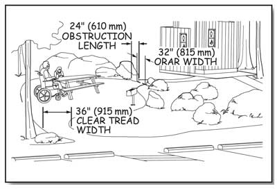
Figure 40—The clear tread width is the unobstructed width of the traveling surface.
All outdoor recreation access routes in a recreation site don't necessarily have to be the same width. Consider the number of people who will use the route at the same time and how they will want to use it—single file or walking and talking side by side—and design accordingly. For example, a 60-inch (1,525-millimeter) -wide main route may be designed to connect a group of campsites to important constructed features, such as a rustic outdoor amphitheater, toilet buildings, or water hydrants. Secondary routes, such as a spur from the main route to a quiet, intimate path along a stream, may be only 36 inches (915 millimeters) wide.
Two people using wheelchairs need a 60-inch (1,525-millimeter) -clear tread width to pass comfortably and safely on an outdoor recreation access route. However, this width isn't always appropriate or required. Where the clear tread width of a route is less than 60 inches (1,525 millimeters), passing spaces are required at least every 200 feet (61 meters). Passing spaces must be at least 60 inches (1,525 millimeters) wide (including the route width) by 60 inches (1,525 millimeters) long (figure 41).
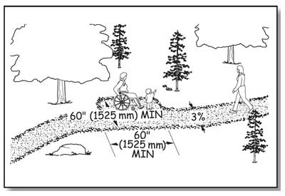
Figure 41—Minimum required dimensions for a passing space for an outdoor recreation access route or a beach access route.
Another option allows a T-intersection of two outdoor recreation access routes or other walking surfaces to be a passing space (figure 42) provided that the arms and stem of the T-shaped space extend at least 48 inches (1,220 millimeters) beyond the intersection. Either configuration would provide enough room for a person to move to the side and let an oncoming person pass along the route. The cross slope of a passing space must not exceed 1:33 (3 percent). Where the surface is paved or is built with boards, the slope must not be steeper than 1:48 (2 percent) in any direction.
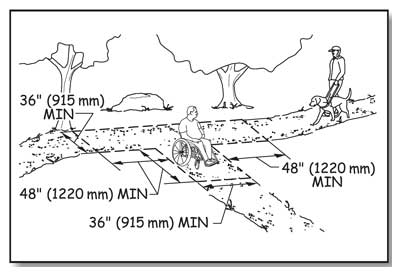
Figure 42—A T-intersection may be used as a passing space on an outdoor recreation access route or a beach access route if it has dimensions as shown, or larger.
Design Tip
Access route width may vary.
The 36-inch (915-millimeter) minimum clear tread width is just that—a minimum. To determine how wide the outdoor recreation access routes in a project should be, look at the level of development of the site and how the site will be used. In a more highly developed area, a 48- or 60-inch (1,220- or 1,525-millimeter) -wide route may be appropriate, while a 36-inch (915-millimeter) -wide tread may be a better fit in a less developed site.
Tread Obstacles on Outdoor Recreation Access Routes
A tread obstacle is anything that interrupts the evenness of the tread surface. On outdoor recreation access routes, an obstacle may occur where a tree root or rock protrudes above the surface or where two different surfaces abut, such as when a concrete path joins an asphalt path. If they are pronounced, tread obstacles can pose a serious tripping hazard. Where tread obstacles exist along an outdoor recreation access route, they must not be more than 1 inch (25 millimeters) high. Where the surface is paved or is built with boards, obstacles must not be more than ½ inch (13 millimeters) high.
Design Tip
Avoid the use of stairs on outdoor recreation access routes.
In new construction, stairs aren't allowed on outdoor recreation access routes except at viewing areas where there is a condition for an exception. For new recreation sites, select locations that will not require the use of stairs.
Avoid the use of outdoor stairs wherever possible. Sometimes, an alteration project at an existing recreation site includes an area where stairs can't be avoided. When stairs are unavoidable, they should generally meet the requirements for stairs in Architectural Barriers Act Accessibility Standards. Although these requirements are not mandatory for stairs that aren't part of a means of egress for a building, compliance will ensure the stairs are safe and comfortable to use.
The accessibility guidelines for outdoor recreation areas do not require handrails for stairs. Consider the safety of the people using the stairs and the setting when deciding whether handrails are appropriate. What is the expected amount of use? How can the appearance of overdevelopment be avoided while providing for safe use of the stairs? When deciding whether handrails are necessary on outdoor stairs, also consider how many should be provided. For example, a few steps at an individual campsite may not need a handrail. Where a handrail would be helpful, one handrail in the center may accommodate low-volume, two-way traffic. Treads that are just wide enough for one-way traffic could have a handrail on one side. Two handrails may be needed if stairs are provided in hightraffic areas.
Openings in Outdoor Recreation Access Route Surfaces
Openings are gaps in the surface of an outdoor recreation access route. Gaps include spaces between the planks on a boardwalk or in a drainage grate. Openings that are big enough to allow wheels, cane or crutch tips, or shoe heels to drop through or get stuck are hazards that shouldn't occur in pedestrian routes (figure 43). Openings up to a half of an inch (13 millimeters) wide are permitted. Place elongated openings that are more than a quarter of an inch wide with the long dimension perpendicular or diagonal to the primary direction of travel (figure 44).
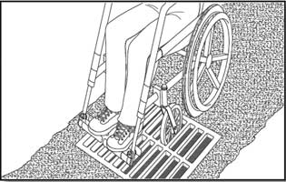
Figure 43—Big openings in outdoor recreation access route surfaces create problems.
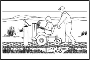
Figure 44—Elongated openings must be perpendicular to the direction of travel.
Protruding Objects and Outdoor Recreation Access Routes
Objects that extend into the travel way of an outdoor recreation access route from the side or from overhead can be hazardous to people who are paying more attention to their companions than the travel route, as well as to people who are blind or have low vision. Protruding objects are defined as constructed features (such as signs) that extend into the clear width area of an outdoor recreation access route, resting interval, or passing space and that are between 27 inches (685 millimeters) and 80 inches (2,030 millimeters) above the travel surface. Do not allow constructed features to extend into the clear width area more than 4 inches (100 millimeters, figure 45).
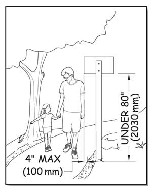
Figure 45—Constructed features can't extend into the clear width area more than 4 inches if they are between 27 and 80 inches (685 to 2,030 millimeters) above the walking surface.
Accessibility guidelines do not consider natural elements (such as tree branches and rock formations) to be protruding objects. Provide and maintain clearance from natural elements around outdoor recreation access routes in accordance with your unit's standards, keeping in mind overhanging hazards to people who are blind or have low vision, or are not focused on the route ahead.
Design Tip
Edge protection may be used for outdoor recreation access routes.
Edge protection is a raised curb, wall, railing, or other structure that defines the edge of a travel surface and may help keep people on the travel surface. Edge protection is not required for accessibility on outdoor recreation access routes, and it is not usually desirable in outdoor environments because it isn't as easy to see or detect objects near the ground. However, edge protection may be desirable for safety or other reasons. Edge protection curbs (figure 46) in an outdoor environment are required to be at least 3 inches (75 millimeters) high.
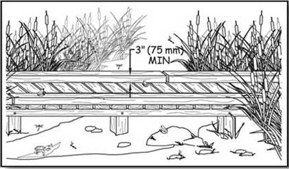
Figure 46—Edge protection is optional on an outdoor recreation access route, but if present, edge protection must be at least 3 inches high.
Gates and Barriers
If gates or barriers are constructed to control access to outdoor recreation access routes, beach access routes, or trails, include openings wide enough to allow hiker passage (figures 47 and 48) that complies with ODAAG, section 1017.3 Clear Tread Width. That section requires 36 inches (915 millimeters) of clear width. However there may be areas where Condition for an Exception 3 applies (for instance, where providing a 36-inch-wide opening would allow the entrance of motorized vehicles that are not permitted behind the barrier). In such circumstances, 32 inches (815 millimeters) clearance, the same as is required for an interior door, will provide pedestrian access to the recreation opportunity without permitting motorized access behind the gate or barrier. Be sure to document all exceptions. If there is a gate, measure the clear opening width with the gate open 90 degrees. As required in ABAAS, section 307.2, do not allow projections into the clear opening width between the trail surface and 27 inches (685 millimeters) above the trail surface. Projections of more than 4 inches (100 millimeters) aren't allowed between 27 inches (665 millimeters) and 80 inches (2,030 millimeters) above the trail surface. ABAAS, section 404.2.3 also contains allowances for projections of closers and stops that aren't likely to apply to trail barriers or gates. Examples of blockage by and passage around barriers are shown in figures 21 and 22. The clear opening width is the key. The travel surface must meet the same requirements as the adjacent outdoor recreation access route, beach access route, or trail.
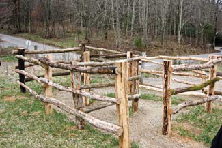
Figure 47—The winding configuration of this rustic chicane where the Appalachian Trail crosses Tennessee Highway 91 and the Osborne farm allows pedestrians to pass through the fence to use the trail but keeps motorized users out and horses inside the farm fence.
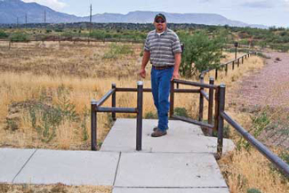
Figure 48—A steel kissing gate on the Prescott National Forest prevents passage by motor vehicles. The design balances the principles of the Built Environment Image Guide with the needs for access control. Sturdy, vandal-resistant materials were needed to discourage determined off-road vehicle users.
Gate hardware must comply with ABAAS, section 404.2.7. This section refers to the requirement in ABAAS, section 309, that controls and operating mechanisms have to be operable with one hand without tight grasping, pinching, or wrist twisting, using a force no greater than 5 pounds (2.2 newtons), as explained in "Reach Ranges and Operability Requirements." It also requires that operable parts of latches must be located between 34 inches (865 millimeters) and 48 inches (1,220 millimeters) above the trail surface. The operating hardware for sliding gates must be exposed and usable from both sides. In alterations, a projection of five-eighths of an inch (16 millimeters) into the clear width is allowed for the gate latch stop.
Designs for several accessible gates (figure 49) are available in the Forest Service publication "Accessible Gates for Trails and Roads" at http://fsweb.mtdc.wo.fs.fed.us/php/library_card.php?p_num=0623%202340. The publication includes drawings for gates that can be used to close roads and trails to motor vehicle access while still providing providing 36-inch-wide (915-millimeters-wide) passage for pedestrians and devices that meet the definition of a wheelchair (see figures 6 through 11), as well as other gate designs that allow pedestrian and equestrian passage while prohibiting motor vehicle access.
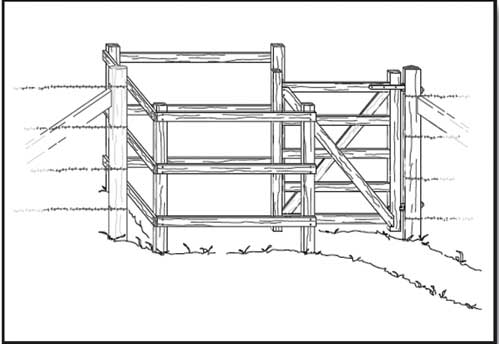
Figure 49—This timber kissing gate is one of the designs available in the Forest Service publication Accessible Gates for Trails and Roads.
Providing Comforts and Conveniences—Constructed Features
Constructed features are the site furnishings and other elements provided in picnic areas, campgrounds, and other recreation sites. The requirements for constructed features are addressed in sections 3, 4, and 5 of FSORAG. Section 3 "Recreation Sites" addresses the layout of recreation sites, including vehicle parking, camping and picnic units, viewing areas, and use of the international symbol of accessibility and other signs. Section 4 "Constructed Features in Recreation Sites" addresses individual site amenities, including picnic tables; fire rings; fire grills; fireplaces; wood stoves; tent pads and platforms; trash, recycling, and other essential containers; telescopes and periscopes; utilities; water hydrants; utility sinks; and outdoor rinsing showers. Section 5 "Buildings in Recreation Sites" addresses requirements for buildings that are not included in ABAAS, such as camp shelters and pit toilets. These subjects will be addressed in the same order in this document.
Construct, purchase, and install only elements and constructed features that comply with the accessibility guidelines, as directed by the Forest Service policy of universal design. For example, even if steep terrain or other conditions in an alteration project at a recreation site preclude complying with the slope requirements for the outdoor recreation access route to a picnic table or camping unit, all the components and furnishings still must comply with the relevant sections of FSORAG. Individuals can select the location where they want to picnic or camp without being limited by the location of accessible features of the picnic or camping unit. This requirement includes all picnic tables, pedestal grills, and other features in a picnic area or campground if they are purchased or constructed by or on behalf of the Forest Service. The few exceptions to this general rule are explained in the section for each feature.
Construction Tip
Determine if features are really accessible
Manufacturers don't necessarily understand accessibility requirements. Some manufacturers advertise their products as "accessible" or "Americans with Disabilities Act compliant," even though they aren't. Accessible means a product is in compliance with the applicable accessibility requirements. Compare the dimensions of the product to the applicable Architectural Barriers Act Accessibility Standards or Forest Service Outdoor Recreation Accessibility Guidelines requirements to make sure that a product, such as a picnic table or fire ring, is truly accessible. Ask the manufacturer for the shop drawings or for the location of a retailer or campground near you where you can examine the product.
When individual elements and constructed features wear out or are damaged and must be replaced, the Forest Service requires that the renovated or replaced elements or features be accessible. However, if the ground under the element isn't changed, this work doesn't trigger the surface and slope requirements for clear floor and ground space.
FSORAG doesn't require that any particular constructed feature be provided in a picnic area or campground. If there were no plans to provide outdoor rinsing showers, utility sinks, or utility hookups at a campground, FSORAG wouldn't require them to be installed. However, if a feature is provided, FSORAG must be met.
Construction Tip
Fix it while you’re there.
Bringing the surface and slope of the ground under an individually replaced element or constructed feature up to new construction standards isn't required. However, you may be able to save time and money over the long haul by shaping and smoothing the surface before putting in the new table. If you integrate logical improvements every time you replace a component, accessibility may be achieved without a large construction project.
Design Tip
How to design features that are not addressed in Forest Service Outdoor Recreation Accessibility Guidelines.
If you want to provide a constructed feature that isn't addressed in Forest Service Outdoor Recreation Accessibility Guidelines (FSORAG), design it using the basic building blocks of accessible design, including clear space dimension requirements for a wheelchair and reach ranges found in Architectural Barriers Act Accessibility Standards (ABAAS).
For example, lantern hooks are sometimes provided in campgrounds, but FSORAG doesn't address them. Using the information in ABAAS and the principles of universal design, design the hooks to be usable by the greatest number of campers. The hooks should be placed within the reach of a person who is seated, as well as a person who is standing.
Use a hinged device to adjust the height of the hook or install two hooks at different heights. Consider safety when designing a post with multiple or adjustable hooks. Ensure the lantern hook has appropriate clear space to allow a person in a wheelchair to approach it from the front or the side, and place the hook where it will not create an obstacle to people moving around the campsite. The clear space for the lantern hook shouldn’t overlap the outdoor recreation access route.
Clear floor or ground space is required around the usable sides of each constructed feature, but the size of the clear space varies with the feature. The differences are based on how each feature is used and whether users need to approach just one side of the feature or all sides of it. For instance, users may only need to get to the front of a pedestal grill that doesn't rotate or to the front and sides of a water hydrant, but they need to get to all sides of a picnic table or fire ring.
When several constructed features are grouped together, such as in a camp living area or picnic unit, their clear spaces may overlap. For example, the 48-inch (1,220-millimeter) clear space around a picnic table may overlap the 48-inch (1,220-millimeter) clear space around a pedestal grill. Do not allow the clear space at a constructed feature within a camp living area or picnic unit to overlap the outdoor recreation access route that connects the camp living area or picnic unit to the rest of the recreation site. Also, do not allow the clear space to overlap any outdoor recreation access route that is adjacent to the camp living area or picnic unit but leads to a common use feature, such as a water hydrant.
Ensure that individual constructed features, such as water hydrants, are connected by outdoor recreation access routes in developed recreation sites, by beach access routes on beaches, and by trails when features are located along a trail. More information about connectivity requirements is provided in the parts of the guidebook on recreation site layout and constructed features.
Within individual camp living areas or picnic units, the slope, surface, and size of the required clear spaces of individual constructed features usually provide the required connectivity and eliminate the need for separate outdoor recreation access routes. The overlapping or adjacent clear spaces function as the outdoor recreation access routes, beach access routes, or trails. Sometimes features are spread apart to limit the amount of change to the natural setting, and the clear spaces for individual features are not adjacent or overlapping. In these cases, provide the appropriate outdoor recreation access routes, beach access routes, or trails to connect the features.
Reach Ranges and Operability Requirements
In this guidebook, you will see the provision "Controls and operating mechanisms must comply with the requirements for reach ranges and operability specified in ABAAS, sections 308 and 309" whenever a site feature has buttons, knobs, handles, or other controls or operating devices. One of the basic principles of universal design and accessibility is to provide controls that most people can reach and use.
Design Tip
Understand forward reach and side reach terminology.
When the phrases "forward reach" and "side reach" are used in the context of accessibility, they don't refer to the object a person is trying to reach. They refer to the position of the person doing the reaching. A forward reach means that the person is facing the object and reaching forward toward it (figure 50). A side reach means that the person's side is closest to the object, and the person is reaching either to their right or left towards the object (figure 51). People using wheelchairs can't reach as far forward over their laps as they can reach to the side. They also need correctly sized spaces to position their wheelchairs to be able to reach objects from the front and from the side. That is why there are different height and clear floor space requirements for forward and side reaches.
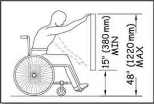
Figure 50—The requirements for unobstructed forward reach.
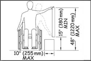
Figure 51—The requirements for unobstructed side reach.
ABAAS, section 309 requires that controls and operating mechanisms be operable with one hand without tight grasping, pinching, or wrist twisting, using a force no greater than 5 pounds (2.2 newtons). To test a control, try operating it by applying light force with one closed fist, without bending your wrist.
Section 308 of ABAAS identifies the following reach requirements:
-
Unobstructed Reaches—When a forward or side reach is unobstructed, the object to be reached must be no higher than 48 inches (1,220 millimeters) and no lower than 15 inches (380 millimeters) above the floor or ground (figures 50 and 51). For side reaches only, an object that is below the object to be reached and isn’t more than 10 inches (255 millimeters) wide doesn't count as an obstruction.
-
Obstructed Forward Reach—When an object must be reached over an obstruction, the clear floor space must extend beneath the obstruction for at least as far as the reach depth over the obstruction. The object to be reached is not allowed to be under the obstruction. If the obstruction is 20 inches (510 millimeters) deep or less, the object to be reached must be between the top of the obstruction and 48 inches (1,220 millimeters) above the floor or ground (figure 52). If the obstruction is more than 20 inches (510 millimeters) deep, the object to be reached must be between the top of the obstruction and 44 inches (1,120 millimeters) above the ground or floor (figure 53). The obstruction must not be more than 25 inches (635 millimeters) deep.
-
Obstructed Side Reach—For side reaches, obstructions must not be more than 34 inches (865 millimeters) high or 24 inches (610 millimeters) deep. The object to be reached is not allowed to be under the obstruction. If the reach depth is 10 inches (255 millimeters) or less, the object to be reached must be 48 inches (1,220 millimeters) or less above the ground or floor (figure 54). If the reach depth is between 10 and 24 inches (255 and 610 millimeters), the object to be reached must not be more than 46 inches (1,170 millimeters) above the floor or ground (figure 55).
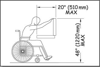
Figure 52—The requirements for obstructed high forward reach, narrower obstacles.
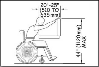
Figure 53—The requirements for obstructed high forward reach, wider obstacles.
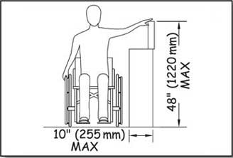
Figure 54—The requirements for obstructed high side reach, narrower obstacles.
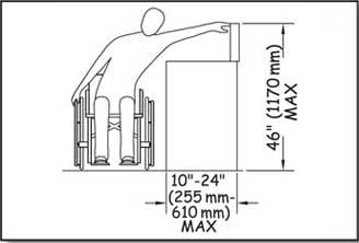
Figure 55—The requirements for obstructed high side reach, wider obstacles.
Grab Bars
Grab bars are usually provided in buildings to provide stability and allow people to use their arms to assist in movement over short distances. The most common location for grab bars is in restrooms. Grab bars must comply with the reach range requirements of ABAAS, section 308, as explained in "Reach Ranges and Operability Requirements." They must also comply with the size, strength, finish, and position requirements in ABAAS, section 609 as follows:
-
Grab bars with circular cross sections must have a diameter no less than 1¼ inches (32 millimeters) and no more than 2 inches (51 millimeters). Grab bars with noncircular cross sections must not be more than 2 inches (51 millimeters) across and must be 4 to 4.8 inches (100 to 120 millimeters) around. Figure 56 shows how this is measured.
-
Grab bars and any wall or other surfaces adjacent to grab bars must have rounded edges and are not allowed to have sharp or abrasive surfaces.
-
Grab bars must be installed so they don't rotate within their fittings.
-
Grab bars have to be strong enough to support 250 pounds (1,112 newtons) of pressure at any point on the grab bar, fastener, mounting device, and supporting structure.
-
The space between the wall and the grab bar must be 1½ inches (38 millimeters). There must also be a space of 1½ inches (38 millimeters) between the grab bar and any projecting objects below or at the ends of the grab bar. There must be at least 12 inches (305 millimeters) between the grab bar and any projecting objects above it, except multiple grab bars only have to be 1½ inches (38 millimeters) apart.
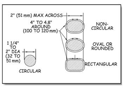
Figure 56—The requirements for the diameter and circumference of grab bars.
Recreation Site Layout
Designing an attractive and functional recreation site is an art as well as a science. Accessibility is, of course, one of the many design parameters for any recreation site.
Vehicle Parking
Within recreation areas, vehicle parking is normally either concentrated into parking lots for more than two vehicles at group areas or distributed into parking spurs designed to hold one or two vehicles or trailers at an individual picnic or camping unit. Vehicle parking lots and other parking spaces that aren't associated with an individual camping or picnic unit must comply with the same requirements as vehicle parking lots for buildings. These requirements can be found in ABAAS, sections 208 and 502. However, slip resistance is not required for parking in recreation areas because leaves and needles, dirt, ice, snow, and other surface debris and weather conditions are components of the natural environment that would be difficult, if not impossible, to avoid.
Parking spurs for one or two vehicles, recreational vehicles (RVs), or trailers at individual picnic or camping units or at parking spaces for RV dump stations must comply with the requirements in section 3.1 of FSORAG. Parking spurs have two components; driveways and parking areas. The driveway is primarily a vehicle travel way that functions as an extension of the recreation site roadway. It provides vehicular access and a transition between the recreation site road and a vehicle parking area. The vehicle parking area is the section of the parking spur where vehicles (cars, vans, recreational vehicles, trucks, trailers, and so forth) are parked. These definitions are important because the scoping and technical requirements vary based on the specific part of the parking spur being addressed. Figure 57 shows the parts of a parking spur.
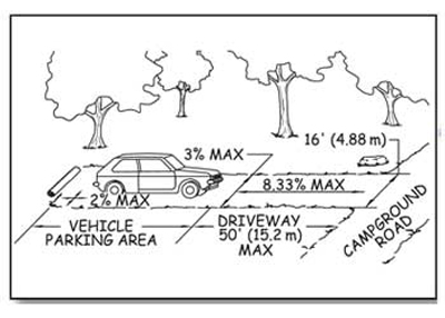
Figure 57—The components of a campground parking spur.
Because people use the parking spur to get to and from their vehicle and to get around the recreation site, ensure that the surface of the entire parking spur is firm and stable as explained in "Surfaces for Outdoor Recreation Access Routes" of this guidebook.
Ensure each vehicle parking area that is adjacent to a camp living area is at least 16 feet (4.88 meters) wide. The 16-foot (4.88-meter) width is the same as the standard width for an accessible parking stall for vans.
Sometimes, a single parking area for a double camping unit accommodates two vehicles side-by-side. In these parking areas, the space between the two vehicles can be used to access both vehicles, so you can reduce the total width of the two non-RV parking areas from 32 feet (9.76 meters) to 24 feet (7.32 meters).
Design Tip
Determine parking requirements for walk-in camping units.
For walk-in camping units, the required parking area width depends on whether the parking area is part of the camping unit or in a group parking lot. If the walk-in unit has its own parking spur, then it falls under Forest Service Outdoor Recreation Accessibility Guidelines parking spur requirements and the parking area should be 16 feet (4.88 meters) wide (as required by the vehicle parking area provision), or less if a condition for an exception applies. If the parking space is part of a group parking area such as a 10-car parking lot that is provided for eight walk-in units, the whole parking lot must meet the requirements of Architectural Barriers Act Accessibility Standards, sections F208 and 502. In such a 10-car parking lot, 9 parking spaces would be standard width and 1 would be 16 feet (4.88 meters) wide to comply with the van-accessible specifications of an 8-foot (2.44-meter) -wide parking space and an adjoining 8-foot ( 2.44-meter) -wide access aisle.
Provide enough width for full size accessible RVs and trailers in campgrounds that are designed to accommodate them (figure 58). A 16-foot (4.88-meter) -wide parking area will accommodate cars, vans, and the majority of RVs and trailers. However, a vehicle parking area that is 20 feet (6 meters) wide is required to accommodate lifts, ramps, and other assistive equipment that allow RV owners to enter, exit, and move around all sides of larger accessible RVs and trailers. The dimensions are based on an 8-foot (2.44-meter) -wide vehicle, an 8-foot (2.44-meter) -wide space on the passenger side for operation of the lift or ramp with room to maneuver and a 4-foot (1.22-meter) -wide clear space along the driver's side.
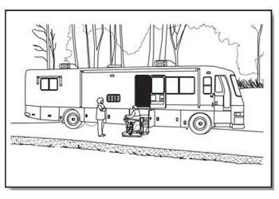
Figure 58— An accessible recreational vehicle with a wheelchair lift.
When parking areas for large accessible RVs accommodate two vehicles side-by-side in a parking area serving a double camping unit, the space between the two vehicles can be used to access both vehicles. Less width is required to provide the same access, so you can reduce the total width of the two RV parking areas from 40 feet (12 meters) to 36 feet (11 meters).
To maximize accessibility while protecting the natural environment, only a limited number of vehicle parking areas in campgrounds with RV camping units must be 20 feet (6 meters) wide. The minimum number of required 20-foot (6-meter) -wide vehicle parking areas is based on the total number of camping units provided in the RV campground (table 3).
Table 3—The number of recreational vehicle (RV) parking areas required to be accessible.
| Number of Camping Units | Minimum Number of 20-foot (6-meter) -Wide Vehicle Parking Areas Required in Campgrounds With Units Designed for Large RVs and Trailers |
|---|---|
| 1 | 1 |
| 2 to 25 | 2 |
| 26 to 50 | 3 |
| 51 to 75 | 4 |
| 76 to 100 | 5 |
| 101 to 150 | 7 |
| 151 to 200 | 8 |
| 201 and over | 8 plus 2 percent of the number more than 200 |
Basing the number of required 20-foot (6-meter) -wide RV parking areas on the number of RV camping units is similar to the approach used by ABAAS for accessible hotel rooms. The minimum required number of accessible rooms is proportional to the total number of rooms in the hotel. Similarly, the minimum number of accessible RV parking areas is proportional to the total number of RV camping units in the campground.
For example, in a 50-unit campground that accommodates large RVs and trailers, a minimum of three vehicle parking areas must be 20 feet (6 meters) wide. The vehicle parking areas for the remaining 47 camping units must be at least 16 feet (4.88 meters) wide, with the exceptions previously noted.
When designing a new campground, remember that table 3 shows minimum requirements. Larger RVs and trailers with bump-out sections are increasingly common. Areas where many recreationists use larger RVs and trailers may require providing more camping units with a 20-foot (6-meter) -wide vehicle parking area.
Some national forests have found the 20-foot (6-meter) -wide RV parking area to be an appropriate design standard for use throughout their RV campgrounds.
If there are one or more conditions for an exception that prevent constructing a full-width parking area (at least 16 feet (4.88 meters) wide or 20 feet (6 meters) wide as required by table 3), you can reduce the width to 13 feet (4 meters), the width of an accessible parking space for cars. Because new recreation site locations should be chosen carefully to ensure accessibility requirements can be met, this exception should hardly ever be taken. Even when conditions for exception are numerous and extreme, at least 20 percent of parking areas must be full width. When only one or two non-RV parking areas are provided in a recreation area, no exception is permitted. When three to 10 non-RV parking areas are provided, at least two of the vehicle parking areas must be full width.
There are separate slope requirements for vehicle parking areas and driveways because of the different functions they perform. Do not allow the slope of the vehicle parking area to exceed 1:48 (2 percent) in any direction. However, when the surface is not paved or built with boards, slopes up to 1:33 (3 percent) in any direction are allowed when needed for proper drainage.
Design Tip
Determine how long the parking area should be.
Forest Service Outdoor Recreation Accessibility Guidelines has requirements for parking area or spur width, but not length. Length of parking area spurs depends on the terrain and the type of vehicles that are expected to use the parking area. Ordinary parking lots are normally designed with 20-foot (6-meter) -long parking spaces to accommodate passenger vehicles, so parking areas should be at least 20 feet (6 meters) long. A large trailer with a towing vehicle could be up to 60 feet (18 meters) long and a bus-style recreational vehicle (RV) could be up to 45 feet (14 meters) long.
Some campgrounds include parking spurs of various lengths. This limits campsite choices for campers with larger trailers or RVs, but also minimizes hardened surfaces and ground disturbance, especially on difficult terrain. Provide information online and at the campground regarding the length of parking areas. Campers with larger trailers and RVs will appreciate it.
The running slope of a parking spur driveway may be up to 1:12 (8.33 percent) for 50 feet (15 meters). An exception for areas of steeper terrain permits the running slope to be up to 1:10 (10 percent) for 30 feet (9 meters). In alterations of existing campgrounds only, a second exception permits the running slope to be up to 1:10 (10 percent) for distances up to 50 feet (15 meters) if the first exception can't be met because of a condition for an exception. This second exception does not apply to new construction.
The cross slope of a parking spur driveway must not exceed 1:33 (3 percent). However, the cross slope of driveways may be as steep as 1:20 (5 percent) if needed for proper drainage or to provide a transition from the campground road to the vehicle parking area. For example, if a back-in parking spur is adjacent to an interior campground road that has a running slope steeper than 1:20 (5 percent), the driveway may need a steeper cross slope to make the transition from the running slope of the road to the relatively level vehicle parking area (figure 59).
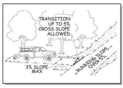
Figure 59—The transition from a parking spur driveway to a campground road.
Design Tip
Allow for pedestrians in the driveway.
Because people move around the vehicle parking areas and along the driveways, parking spurs also have to be able to function as outdoor recreation access routes.
Keep the running and cross slopes of driveways, even in alterations, as gentle as possible so that vehicles and people can easily and safely navigate into and out of the camping unit, erosion is minimized, and road design and construction standards are met.
Camping Units
A camping unit is a part of a campground that is used by an individual or group for camping separate from other parties using the recreation site. A camping unit commonly includes the camp living area, a parking spur, and a space to pitch a tent (figure 60). FSORAG doesn't require a specific number or type of camping units or constructed features, but all camping units and the site furnishings and constructed features in them must meet the applicable FSORAG requirements.
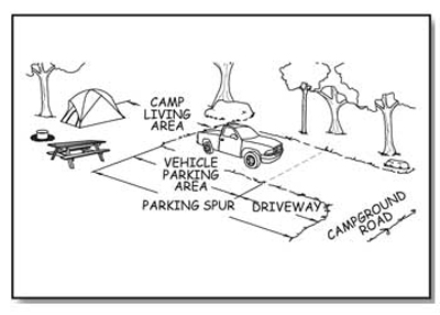
Figure 60—The components of a camping unit.
The camp living area is the space where tables, fire rings, and grills are located. This area is often adjacent to the parking spur. The minimum size of a camp living area is determined by the type and number of constructed features provided and the required clear space around each feature. Ensure the surface of camp living is firm and stable, and that the surface material used is appropriate to the setting and level of development. Do not allow the slope of the ground surface in camp living areas to exceed 1:48 (2 percent) in any direction, except when the surface is unpaved or is not built with boards. In those cases, the slope may be up to 1:33 (3 percent) for necessary drainage.
To meet outdoor recreation access route requirements, a route must connect all the features within each camping unit. Usually, the slope, surface, and size requirements for the overlapping or adjacent clear spaces of the constructed features within camp living areas eliminate the need for separate outdoor recreation access routes within the camp living area. When features are spread apart to limit the amount of change to the natural setting, provide outdoor recreation access routes to connect the features.
There must also be an outdoor recreation access route connecting each camping unit with the common use features that are provided at the campground, such as toilets, showers, water hydrants, garbage receptacles, parking spaces, and beach access. Ensure this outdoor recreation access route does not overlap the clear spaces of the camp living area so that people using the constructed features in the camp living area will not obstruct travel along the outdoor recreation access route.
There are some exceptions to the requirement that outdoor recreation access routes must connect everything.
-
When work is done to improve an existing camping or picnic facility or a trailhead and a condition for an exception prohibits full compliance with a specific technical requirement on part of an outdoor recreation access route, that part of the outdoor recreation access route only has to meet the technical requirement to the extent practicable.
-
When something is changed within an existing camping facility, but the circulation path isn't altered, the path doesn't have to be brought up to outdoor recreation access route standards.
-
As stated in "Getting From Here to There—Outdoor Recreation Access Routes" of this guidebook, if an accessible vehicle pull-up space is provided at the RV dump station, an outdoor recreation access route is not required to connect the station to the camping units.
-
In campgrounds where the roadway is the primary route from the campsites to the restrooms and so forth, a separate outdoor recreation access route to the same facilities is not required. That roadway is not required to meet the specifications for an outdoor recreation access route. However, there must be a minimum of 32 inches of clear passage through or around any constructed obstacles in the roadway, such as speed bumps.
Even when they're not required, the Forest Service commitment to universal design dictates that outdoor recreation access routes connect as many features as is practicable, given the specific natural constraints of the site, the level of development, and other considerations.
When walk-in camping is provided in a campground, ensure an outdoor recreation access route connects the camp living area to the parking spur or parking lot. If the terrain is steep (or there's another condition for an exception) and the work is an alteration to an existing site, compliance with the slope requirements for the outdoor recreation access route to those walk-in units isn't required.
When a camping unit is located near a trail (rather than in a campground accessed by vehicles), the connection between that unit and the trail and the connections between the constructed features within that camping unit must comply with FSTAG requirements for trails, not the outdoor recreation access route requirements.
Picnic Units
A picnic unit is a part of a picnic area that contains one or more constructed features used for picnics by an individual or a group. Each picnic unit may be used separately from other parties using the recreation site. All site furnishings and constructed features that are provided in a picnic unit must meet the applicable FSORAG requirements. The minimum size of a picnic unit is determined by the required clear space around each feature and the type and number of provided constructed features
Ensure all pedestrian routes that are provided in a picnic area meet outdoor recreation access route standards. Use an outdoor recreation access route to connect all features within each picnic unit. Usually, the slope, surface, and size requirements for the overlapping or adjacent clear spaces of the unit's constructed features within a picnic unit eliminate the need for separate outdoor recreation access routes within the unit. When features are spread apart to limit the amount of change to the natural setting, provide an outdoor recreation access route to connect the features.
If a picnic area only has one or two picnic units, connect all units with an outdoor recreation access route to the area's common use features, such as toilets, showers, water hydrants, garbage receptacles, parking spaces, and beach access routes. If a recreation site has more than two picnic units, use an outdoor recreation access route to connect at least 20 percent of the units (but never less than two) to the common use features at the site. For example, in a picnic area with 20 units, all site furnishings (tables, grills, etc.) must be accessible, and a minimum of four picnic units must be connected by an outdoor recreation access route to the area's other common use features.
When designing picnic areas, remember locating 20 percent of the units on an outdoor recreation access route is only a minimum requirement. Connect as many units with an outdoor recreation access route to the major features of the site as practicable, given the specific natural site constraints, the level of site development, and other considerations.
FSORAG recognizes that the natural terrain often presents a real obstacle in the outdoor recreation environment. At existing sites that are being renovated, you may not be able to provide an outdoor recreation access route for all picnic units without affecting the fundamental nature of the picnic area and the recreation opportunity. When an existing picnic area is altered or reconstructed and a condition for an exception prohibits full compliance with a specific technical requirement on part of an outdoor recreation access route, that part of the outdoor recreation access route only has to meet the technical requirement to the extent practicable. When something is changed within an existing picnic facility, but the circulation path isn't altered, the path doesn't have to be brought up to outdoor recreation access route standards. Even though it's not required, these changes almost always provide you the perfect opportunity to bring the paths up to outdoor recreation access route standards and follow the Forest Service policy of universal design.
Viewing Areas
Overlooks and viewing areas are designed and constructed to provide scenic vistas and unobstructed views of points of interest, such as a mountain range, a valley, a waterfall, or a unique geologic formation (figure 61). Because overlooks and viewing areas are destination points, they must be accessible so all visitors can enjoy the viewing opportunities. Ensure that each viewing area at an overlook and all the site furnishings, constructed features, and buildings in it, comply with applicable FSORAG and ABAAS provisions. However, when work is done to improve an existing viewing area or overlook and a condition for an exception prohibits full compliance with a specific technical requirement for a clear ground space, unobstructed view, turning space, surface, or slope, you only have to meet the requirement to the extent practicable.
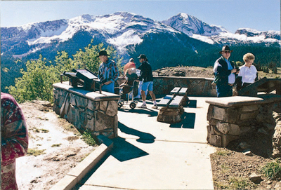
Figure 61—The overlook on the San Juan Skyway, a scenic byway in Colorado, allows all visitors to enjoy the view.
Viewing areas in recreation settings must be located along an outdoor recreation access route that connects to the other major features at the site, including the parking area. There are some exceptions to the requirement to connect everything with outdoor recreation access routes. Sometimes vistas can only be viewed from an area with difficult terrain. If a condition for an exception prohibits full compliance with a specific technical requirement for a portion of an outdoor recreation access route at a viewing area, you only must ensure that portion of the outdoor recreation access route complies with the technical requirement to the extent practicable. When something is changed within an existing overlook or viewing area, but the circulation path isn't altered, you don't have to bring the path up to outdoor recreation access route standards. Even though it's not required, renovations almost always provide you with the perfect opportunity to bring the paths up to outdoor recreation access route standards so that everyone can get to the viewing area or overlook.
Ensure each viewing area that is required to be accessible has a clear ground or floor space that is at least 36 inches (915 millimeters) by 48 inches (1,220 millimeters) and is positioned for either a forward or parallel approach to the viewing location. Each accessible viewing area must also have at least one turning space that is 60 inches (1,525 millimeters) minimum in diameter (figure 62) or is a T-shaped space with a minimum 60- by 36-inch (1,525- by 915-millimeter) arm and a minimum 36-inch (915-millimeter) -wide by 24-inch (610-millimeter) -long base (figure 63). The clear ground space and turning space may overlap. The turning space requirement is the same as ABAAS section 304.3. These spaces allow someone using a wheelchair or other assistive device to approach and move about the viewing area.
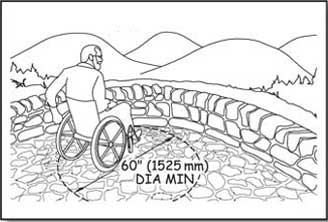
Figure 62—One way to meet the requirements for turning space at a viewing area.
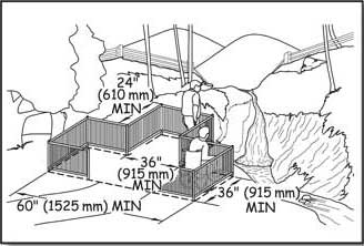
Figure 63—The requirements for a T-shaped turning space at a viewing area.
If there are several viewing areas, provide at least one accessible, unrestricted viewing opportunity for each distinct point of interest. An unrestricted viewing opportunity means a clear field of vision toward the vista or point of interest that extends at least from 32 to 51 inches (815 to 1,295 millimeters) above the entire side of the clear floor or ground space of the viewing area.
Ensure the slope of clear floor or ground spaces and turning spaces does not exceed 1:48 (2 percent) in any direction. When the surface isn't paved or built with boards, allow grades up to 1:33 (3 percent) in any direction if needed for proper drainage. Ensure the surface is firm and stable and of a material that is appropriate to the setting and level of development. Restrict openings in the surface of clear ground spaces and turning spaces to small enough that a ½-inch (13-millimeter) -diameter sphere can't get through them. Place elongated openings more than a quarter of an inch wide with the long dimension perpendicular to the primary direction of travel.
Viewing areas often are adjacent to hazardous dropoffs. When there is a dropoff of more than 30 inches (760 millimeters), provide a guardrail or barrier that complies with the height and opening requirements of the International Building Code, sections 1012.2 and 1012.3.
Barriers such as walls, guardrails, or signs installed for safety reasons could restrict views. However, neither accessibility nor safety measures should be ignored. Designers need to consider different ways of providing for safety without blocking the view. For example, narrow vertical rails, seethrough [sic] panels, or screened openings could be installed, or the designer may be able to build the overlook with a series of tiers or terraces (figure 64). The placement of interpretive signs may also help create a barrier to keep people back from the edge of the overlook without blocking the view (figure 65).
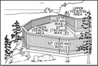
Figure 64—This overlook design has two levels so the railing can be lower at the upper viewing area.
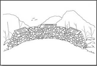
Figure 65—Signs placed to create a barrier at an overlook.
Design Tip
Design guardrails for safety and views.
Providing safety while maximizing viewing opportunities is a challenge for those designing a guardrail or structure adjacent to a dropoff. It's possible to design two viewing levels (see figure 64), where the lower level would be less than 30 inches (760 millimeters) below the upper level.
With this design, a tall guardrail isn't required for the upper level. At the upper level, where the visitors generally approach the viewpoint, a low railing or wall can permit good visibility. The lower viewing level would have a tall guardrail meeting the International Building Code requirements. This lower level provides the "catch" area for the primary level.
If the area or structure doesn't lend itself to a two-level approach, try a see-through 42-inch (1,065-millimeter) -high guardrail (figure 66). Place the vertical rails so that a 4-inch (100-millimeter) sphere can't pass through them. Visibility through this type of guardrail is excellent. The eye level of most adults seated in a wheelchair is above 42 inches (1,065 millimeters), and children sitting on the deck can enjoy the view through the rails.
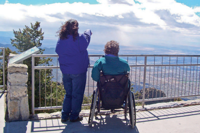
Figure 66—This railing on an overlook at Sandia Crest on the Cibola National Forest is safe, meets code requirements, and provides a great view for people of all heights.
The importance of vertical rather than horizontal rails can't be overemphasized. When children see horizontal rails, they regard them as an inviting ladder that encourages them to climb. A horizontal rail can't protect them from a fall (figure 67).

Figure 67—Caution: Railings with horizontal rails make an inviting ladder for small children.
Use of the International Symbol of Accessibility and Other Signs
Signs provide key information concerning the accessibility of programs and facilities. People often think of the International Symbol of Accessibility (ISA) (figure 68) as an all-purpose sign to be used any time an accessible feature is available, which is not necessarily true.

Figure 68—International symbol of accessibility.
In accordance with ABAAS, section 216, ISA must be posted at only six places:
-
At accessible parking spaces in parking lots with five or more designated parking spaces.
-
Sign van accessible parking spaces in these lots as such.
-
Sign RV accessible parking spaces in these lots as such.
-
Do not post ISA at parking spurs provided at camping units or other individual accessible features.
-
-
At accessible loading zones.
-
At accessible restrooms and bathing facilities.
-
At the main entrance to a building, with an arrow directing people to the closest accessible entrance, if the main entrance is not accessible.
-
On the door to an accessible area of refuge inside multistory buildings.
-
At an accessible means of egress out of a building.
Except for the requirement to post the VAN ACCESSIBLE plaque at van accessible spaces, no other descriptive words are required to be used with ISA. If words are used, use "accessible." Do not use "handicapped."
Where all constructed features and areas comply with the accessibility provisions, you may post ISA, but it is not required. Do not individually sign accessible sites with ISA because this can stigmatize and draw unwanted attention to the individuals using those sites.
When only some constructed features and areas comply with the accessibility provisions, people need to know whether they will be able to use a particular campsite or picnic area. This can be accomplished using several methods, depending on the type of campground or picnic area.
The Federal agency recreation reservation system (http://www.recreation.gov) contains accessibility information about campsites and picnic areas that are registered in the system, including which individual sites are accessible. When using this system to reserve a site, people are automatically notified if they are about to reserve an accessible site. ISA also can be used to identify individual accessible sites on the recreation site map on the Web site describing the recreation site. These are both good ways to provide accessibility information to recreationists with Internet access.
If some—but not all—campsites or picnic areas are accessible and recreationists choose their site when they arrive at the recreation area, provide accessibility information to recreationists as they enter the area. ISA can be used to identify the individual units that comply with the accessibility guidelines on the recreation site map at the entrance kiosk, fee station, bulletin board, or registration area. Post the following type of statement on the registration information sign: "Units 2, 4, 6, and 10 are accessible. If no one in your group needs an accessible site, please fill these units last." Forests that use this type of statement on the registration sign report that visitors generally have complied.
If some—but not all—campsites or picnic areas are accessible and the sites are assigned by a person onsite who can provide information about each unit, you don't have to post accessibility information. The accessible units should be assigned as requested by individuals. The accessible sites that are not assigned to persons with disabilities should be filled last, keeping them available in case they are needed. Do not ask people who request or reserve an accessible site to state or show any type of verification of their disability.
Their vehicles are also not required to display a license plate or placard indicating a disability. This site reservation and assignment process complies with the court-ordered process followed by hotels concerning their accessible rooms.
There is no legal requirement on federally managed lands for ISA signs to be blue and white, even at parking spaces. If ISA is used, post it on a vertical sign in accordance with ABAAS, section 703.7, in high-contrast colors with a nonglare finish. A cream or pale yellow ISA on a brown background complies with this requirement and blends into an outdoor setting.
If you want the local law enforcement agency to be able to issue tickets for illegal parking at accessible parking spaces in parking lots, display ISA in blue and white to comply with the Manual of Uniform Traffic Control Devices (MUTCD), section 2B.39. Although their use is optional, the only approved colors for pavement markings designating accessible parking spaces are blue and white (MUTCD, section 3B.18).
If a sign or kiosk has materials to be handled, such as maps, brochures, fee envelopes, and so forth, design the sign or kiosk so that the materials are displayed within the standard accessible reach ranges in accordance with ABAAS, section 308, as explained in "Reach Ranges and Operability Requirements" of this guidebook. Provide clear floor or ground spaces of 30 by 48 inches (760 by 1,220 millimeters) to allow a forward or parallel approach.
Post the appropriate international symbols where various modes of alternative formats, communication, or adaptive equipment are available. Large print, open captioning, sign language interpreters, and so forth are each represented by a specific symbol (figures 69 through 77).

Figure 69—International symbol for information.

Figure 75—International symbol to indicate sign language interpretation is available.

Figure 72—International symbol for video or film with closed captions.

Figure 70—International symbol for teletypewriter (also referred to as "TTY").

Figure 76—International symbol to indicate large print (18 point) material is available.

Figure 73—International symbol to indicate audio description is available.

Figure 71—International symbol for a telephone with volume control.

Figure 77—International symbol to indicate materials are available in Braille.

Figure 74—International symbol to indicate an assistive listening system is available.
If you have questions about applying any of the above information, please contact your region's recreation accessibility coordinator. Current contact information is available at http://www.fs.fed.us/eng/toolbox/acc/documents/coord.htm#leaders.
Constructed Features in Recreation Sites
All new constructed features at Forest Service recreation sites must meet accessibility requirements. Depending on the type of site, ensure all or a portion of the features are connected to the other features within the recreation site by an outdoor recreation access route as explained in "Recreation Site Layout" of this guidebook.
If constructed features are replaced, but the ground under the feature isn't changed, the surface and slope of the ground under the feature doesn't have to be brought into conformance with accessibility requirements for clear floor and ground space. Because of the Forest Service policy of universal design and the cost savings inherent in accomplishing all anticipated improvement work at an area at once, doing whatever is feasible to improve accessibility while you're working in the area is recommended.
Picnic Tables
All new picnic table installations must comply with requirements for accessible seating spaces, table clearance, slope, and surface. This is true whether the table is in a campground, picnic area, or other recreation site. "Recreation Site Layout" explains how the tables in each of these types of recreation sites must be connected to the other major constructed features at the recreation area. If the picnic tables are provided on trails, ensure the routes connecting them to any other major constructed features in the area comply with the technical requirements for trails.
The number of wheelchair seating spaces that must be provided at each table is based on the length of the picnic table (figure 78). Always ensure at least one wheelchair seating space. For larger tables, one wheelchair seating space is required for each 24 linear feet (7.32 meters) of usable space around the perimeter of the table. Practically speaking, tables up to 9 feet (2.74 meters) long usually require one space. Tables between 10 feet (3.05 meters) and 20 feet (6 meters) long usually require two wheelchair spaces, and so on for longer tables, such as four spaces for tables that are 40 feet (12 meters) long.
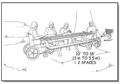
Figure 78—At least two spaces must be accessible at a 10- to 18-foot (3- to 5.5-meter) -long picnic table.
Knee space for wheelchair seating must be at least 30 inches (760 millimeters) wide, 19 inches (485 millimeters) deep, and 27 inches (685 millimeters) high, as measured from the ground or floor to the bottom of the tabletop. Toe clearance of at least 9 inches (230 millimeters) above the ground or floor must extend at least an additional 5 inches (25 millimeters) beyond the required knee clearance. Figure 79 illustrates the required knee and toe space. Toe clearance is required to ensure that someone in a wheelchair is able to sit close to the tabletop, regardless of the design of the picnic table. If the table is constructed with one solid leg on each end, as opposed to an A-shaped frame or two individual legs on each end of the table that would allow the wheelchair to fit in between, the toes of a person in a wheelchair would hit the table leg at the end of the 19-inch (485-millimeter) knee space. Without additional toe clearance, a person in a wheelchair wouldn't be able to get close enough to the tabletop to use it comfortably.
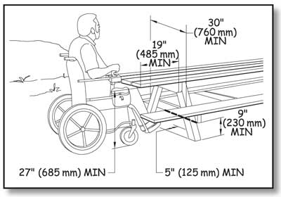
Figure 79—The requirements for knee and toe space at a picnic table.
Construction Tip
Ensure picnic tables are accessible.
Manufacturers often claim their tables are accessible even though they don't meet accessibility requirements. Check the dimensions to verify whether a table is accessible.
Provide clear floor or ground space that is 30 inches by 48 inches (760 millimeters by 1,220 millimeters) at each wheelchair seating space, positioned to accommodate a forward approach to the table (figure 80). No exceptions to the wheelchair seating space requirements are permitted.
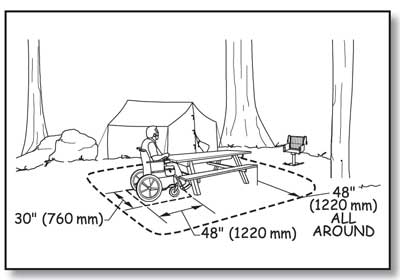
Figure 80—The requirements for clear space at a picnic table.
In addition to the clear floor or ground space for each wheelchair seating space, provide a 48-inch (1,220-millimeter) clear floor or ground space around the usable portions of the table (see figure 82). Measure table clearance from the table seat out. You may reduce the table clear space to 36 inches (915 millimeters) if there is a condition for an exception.
The slope of the required clear floor or ground space for wheelchair seating spaces and for table clearance is not allowed to exceed 1:48 (2 percent) in any direction. Slopes not steeper than 1:33 (3 percent) are permitted, however, where necessary for drainage on surfaces that are unpaved or not built with boards. The surface of the clear floor or ground space must be firm and stable. The type of surfacing used should be appropriate to the setting and level of development.
Design Tip
Design for appropriate picnic table height.
There is no height requirement in Forest Service Outdoor Recreation Accessibility Guidelines for the table top surface of a picnic table or the top of the table benches. Architectural Barriers Act Accessibility Standards require that tops of dining surfaces be 28 inches (710 millimeters) to 34 inches (865 millimeters) above the finished floor or ground. Table tops may be constructed of a number of different materials, and some of them, such as heavy timbers, may be quite thick. The knee space for wheelchair seating at a picnic table must be at least 27 inches (685 millimeters) high. User comfort is important. Generally, benches that are around 18 inches (457 millimeters) above the ground with table top surfaces that are about 32 inches (813 millimeters) above the ground are reasonably comfortable for most people, accommodate common picnic table construction materials, and meet accessibility requirements.
If a condition for exception in an alteration project at an existing site prohibits full compliance with a specific requirement for clear floor or ground space (surface, slope, size, or location), the clear floor or ground space only has to comply with requirements to the extent practicable.
Design Tip
Use different clear spaces for forward and parallel approaches.
A forward approach means that the person is facing the object (see figure 50). A parallel approach means that the person is beside the object (see figure 51). People need different-sized spaces to position their wheelchairs in front of an object and beside an object. That is why there are different clear floor or ground space requirements for forward and parallel approaches.
Design Tip
Use the picnic tables recreationists prefer.
The most popular accessible picnic tables look like ordinary 8-foot-long tables, but the legs are located slightly closer to the center of the table so that they meet wheelchair seating requirements at both ends. The benches are the same length as the tabletop (figure 81). The benches that extend the same length as the table top provide a seat at each corner beyond the table leg. The four corner seats are prized by individuals who may have difficulty stepping over the bench to be seated. At the corner seats, a person simply slides in. Figures 82, 83, and 84 show some examples of accessible tables that can be built by contractors or Forest Service crews. The tables can be locally constructed using the plans available at http://www.fs.fed.us/recreation/programs/accessibility and also available to Forest Service employees at http://fsweb.wo.fs.fed.us/eng/facilities/accrec/tables/. Use the links to view the tables or to save AutoCAD drawings of the tables.
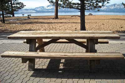
Figure 81—This picnic table at Nevada Beach day use area in the Lake Tahoe Basin Management Unit is a popular design that allows people who use wheelchairs to use either end without the appearance of "separate" space. A Forest Service shield is routed into the cross piece on each end, adding to the design appeal.
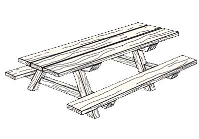
Figure 82—An accessible wood picnic table.
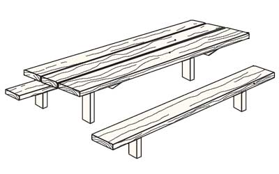
Figure 83—An accessible steel leg picnic table.
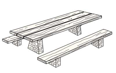
Figure 84—An accessible stone leg picnic table.
Fire Rings, Grills, Fireplaces, and Wood Stoves
An outdoor recreation access route must connect fire rings, grills, fireplaces or wood stoves that are provided in recreation sites to the other major constructed features at the recreation site. If the fire rings, grills, fireplaces, or wood stoves are provided in an area accessed by rail (rather than by vehicle), the routes connecting them to any other major constructed features provided in the area must comply with the technical requirements for trails.
Provide a clear floor or ground space around all usable sides of a fire ring, grill, fireplace, or wood stove so that someone isn't forced to get too close to the heat or fire and risk getting burned. The clear space must extend at least 48 inches (1,220 millimeters) out from the feature and be at least 48 inches (1,220 millimeters) wide. In many cases, a 48-inch (1,220-millimeter) -wide ring of clear space must be provided all around (figure 85), because all sides are usable. For instance, if a pedestal grill can rotate 360 degrees and all positions along that rotation are usable, the 48-inch (1,220-millimeter) clear space must completely surround the grill. If the grill doesn't rotate, clear space is only required on the sides from which access is needed to use the grill. Most fire rings are also usable on all sides. This space may be reduced to 36 inches (915 millimeters) minimum where a condition for exception exists.
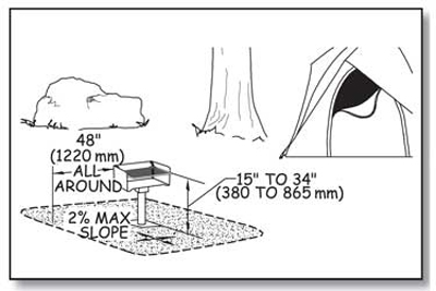
Figure 85—The requirements for height, clear space, and reach range for a pedestal grill.
The slope of the clear floor or ground space must not exceed 1:48 (2 percent) in any direction. When the surface is unpaved or not built with boards, slopes 1:33 (3 percent) and less are allowed where necessary for drainage. The surface of the clear floor or ground space must be firm and stable, and the surface material used should be appropriate to the setting and level of development. However, if a condition for exception in an alteration project at an existing site prohibits full compliance with a specific requirement for clear floor or ground space (surface, slope, size, or location), the clear floor or ground space only has to comply with requirements to the extent practicable.
Ensure the fire-building surface within a fire ring is a minimum of 9 inches (230 millimeters) above the floor or ground surface. Figures 86 and 87 show fire-building surfaces above the ground. This matches the low side reach range in ABAAS.
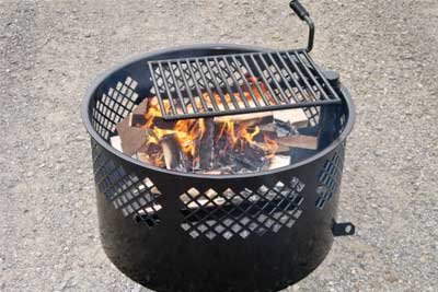
Figure 86—This manufactured fire ring has an internal grate that elevates the fire-building surface 9 inches (230 millimeters) above the ground. The mesh ring above the fire-building grate allows enjoyment of the fire and allows air supply to aid combustion. The cooking grate swings to the side for access to the fire. Photo credit: Jamestown Advanced Products Corporation, Jamestown, NY.
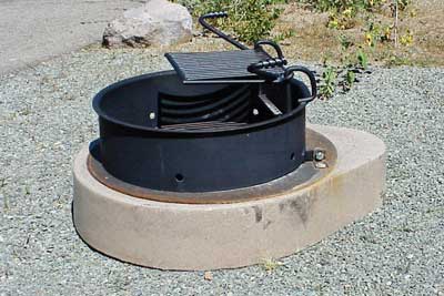
Figure 87—The Prescott National Forest uses standard manufactured steel fire rings on fire-hardened concrete bases so that the fire-building surface meets accessibility requirements for height above the ground.
Some "fire rings" are not constructed features and don't meet the criteria for applying these requirements. For example, in the Boundary Waters Canoe Area Wilderness, people sometimes assemble rings of rocks at popular campsites and build campfires in them. To reduce the risk of campfires becoming uncontrolled fires, they may sometimes be allowed to remain rather than being immediately dismantled by the agency. The accessibility requirements for fire rings do not apply to these temporary, user-built "fire rings."
Controls and operating mechanisms for fire rings, grills (figure 88), fireplaces, and wood stoves must meet the requirements for reach ranges and operability specified in ABAAS, sections 308 and 309 that are explained in "Reach Ranges and Operability Requirements" of this guidebook. Several fire ring and grill manufacturers make models that comply with the reach range and operability requirements.
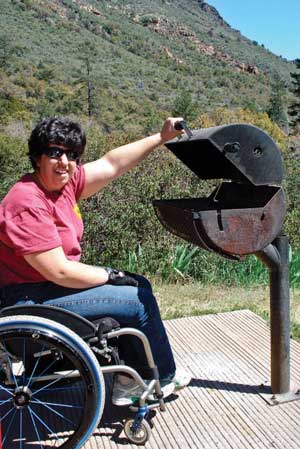
Figure 88—This pedestal grill at a campground on the Coconino National Forest works well for just about everybody.
Accessible models of some other wood-burning devices are not yet readily available. For these devices, compliance with the accessibility requirements for operating controls isn't required until models that meet the requirements are readily available from more than one source.
Ensure that each cooking surface, grill, and pedestal grill meets the requirements for cooking surface height, clear floor or ground space, slope, and surface. The height requirements are based on the height for countertops and the minimum low forward reach range in ABAAS. Ensure the height of the cooking surface is 15 inches (380 millimeters) to 34 inches (865 millimeters) above the floor or ground surface (see figure 85). Practically speaking, the lower range of the required height is associated with fire rings, not pedestal grills. Adjustable pedestal grills may be adjustable beyond the required range, but must include adjustments within the specified range. The adjustments don't have to include the entire range of acceptable heights for cooking surfaces.
Construction Tip
Install pedestal grills at appropriate heights.
Most pedestal grills have adjustable cooking heights. Make sure that the pedestal is installed at a height that allows adjustments to include cooking surfaces 34 inches above the ground or lower, but still provide a reasonable clearance between the cooking surface and the fire-building surface.
Some outdoor fireplaces and custom-built fire rings have a raised edge or wall around the fire-building area, perhaps built out of bricks or mortared stone. In addition to meeting the requirement for a fire-building surface that is at least 9 inches (230 millimeters) above the ground or floor, make sure the width of the raised edge or wall does not exceed 10 inches (255 millimeters). Figures 89, 90, and 91 illustrate the requirements for fire rings and outdoor fireplaces.
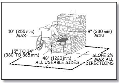
Figure 89—The height, clear space, and reach range requirements for an outdoor fireplace.
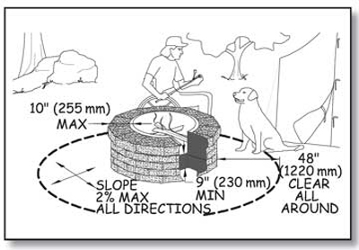
Figure 90—The height and reach requirements for custom-built fire rings.
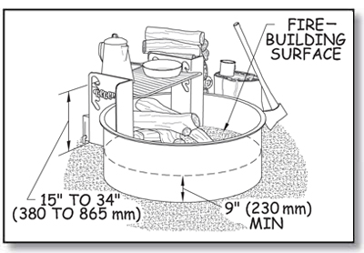
Figure 91—The height and reach requirements for manufactured steel fire rings.
Tent Pads and Tent Platforms
Ensure that tent pads and tent platforms at single camping units in a recreation area meet the following requirements and are connected to the area's other major constructed features by an outdoor recreation access route. At least 20 percent (but not less than two) of the tent pads or tent platforms in group camping units that contain more than one tent pad or tent platform must meet the following requirements and be connected to the area's other major constructed features by an outdoor recreation access route.
Provide a minimum 48-inch (1,220-millimeter) clear floor or ground space on all sides of tents on tent pads and platforms that are required to be accessible. Where there is a condition for an exception, the clear floor or ground space only has to meet the size requirement to the extent practicable.
There is no minimum tent pad size because the types of tents commonly used in recreation sites vary widely in different parts of the country and even in different parts of a single district. For example, at a campground near a wilderness access point, small tents may be used. Large family tents may be common at a more developed campground with numerous constructed features.
Local campground managers are the best source of information about the size of tents commonly used in an area. Adding the 48-inch (1,220-millimeter) or 36-inch (915-millimeter) clear space to the size of a typical tent will determine the minimum size of tent pads and platforms for that campground. Designers may want to provide a range of tent pad or platform sizes to accommodate a variety of tents.
Do not allow the slope of an accessible tent pad or platform to exceed 1:48 (2 percent) in any direction, except when the surface isn't paved or built with boards, the slope may be up to 1:33 (3 percent) if needed for proper drainage. Figure 92 shows the requirements for tent pads and platforms.
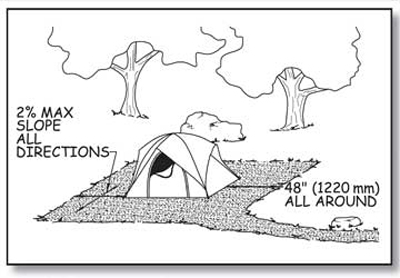
Figure 92—The requirements for a tent pad.
Ensure the surface of an accessible tent pad or platform is firm and stable, can accommodate the use of tent stakes or other devices to secure the tent, and is made of a material that is appropriate for the level of development and setting (figure 93). Where there is a condition for an exception, the surface only has to be as firm and stable as is practicable.
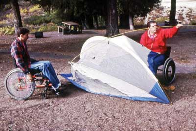
Figure 93—Campers are pitching their tent on a surface that is both accessible and appropriate for the setting.
FSORAG does not require any framed tent platforms or raised tent pads to be constructed. The decision to construct tent pads or tent platforms is a local decision that should be based on what is appropriate for the setting. If tent platforms or raised tent pads are constructed, they must comply with the previously explained clear space, slope, and surface requirements, as well as the following connection requirements.
Accessible surfaces for pitching tents may or may not be at ground level. A level connection that meets outdoor recreation access route standards should be provided to groundlevel [sic] tent floor surfaces. For above-grade platforms or raised tent pads, the outdoor recreation access route may either slope up to the same level as the tent floor surface or end at a clear space that is adjacent to and 17 to 19 inches (430 to 485 millimeters) lower than the tent floor surface. This height is suitable for transferring from a wheelchair to the tent surface.
Benches
Ensure that all benches provided along Forest Service trails or beach access routes or at Forest Service recreation sites (other than those inside a building or in an amphitheater) meet the following requirements. Connect at least 20 percent of benches at a Forest Service recreation area to the area's other major features by an outdoor recreation access route. Benches inside buildings must comply with sections F221.2.1.1, F221.2.2, and 903 of ABAAS. Benches in amphitheaters must comply with the requirements in ABAAS section F221 for assembly areas, including wheelchair spaces, companion seats, designated aisle seats, and lawn seating. Even if most benches in the amphitheater don't have back support, consider providing it at the designated aisle seats required by ABAAS, section F221.4.
Ensure that the front edge of the bench seat is 17 to 19 inches (430 to 485 millimeters) above the ground or floor space. When more than one bench is provided in a common area such as a scenic overlook, at least half of the benches must have back support that runs the full length of the bench
Provide one armrest on at least half of the benches with back support. Consider the visitors who will use a particular area when deciding where to locate an armrest. For people who have difficulty standing up from a seated position, having an armrest can be helpful. However, armrests on both ends of the bench could prevent a person using a wheelchair from being able to transfer onto the bench. A compromise design is a bench with back support and one armrest placed in the middle of the bench. Figure 94 shows a bench that meets these requirements. Another option is to place a single armrest on the end of the bench farthest from the clear floor or ground space.
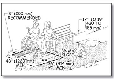
Figure 94—The requirements for benches.
All parts of the bench must be able to withstand 250 pounds (1,112 newtons) applied vertically or horizontally at any point of the seat, fastener, mounting device, or supporting structure. This requirement is the same as the ABAAS requirement for bench strength in section 903.6.
Provide a clear floor or ground space that is 36 by 48 inches (915 by 1,220 millimeters) adjacent to one end of each bench. Do not allow this clear space to overlap the outdoor recreation access route, trail, or beach access route, so that using the bench or clear space doesn't limit travel past the bench and vice versa. Locate the clear space to provide shoulder alignment between a person sitting on the bench and a person seated in a wheelchair occupying the clear space, so that transfers to the bench are convenient and conversations between people on the bench and beside it are comfortable.
Shoulder alignment generally can be achieved by positioning the back of the bench so that it is 8 inches (200 millimeters) closer to the outdoor recreation access route, trail, or beach access route than the back of the required clear floor or ground space adjacent to the end of the bench (see figure 94).
Do not allow the slope of the clear floor or ground space to exceed 1:48 (2 percent) in any direction, except if the surface isn't paved or built with boards, the slope may be up to 1:33 (3 percent) when needed for proper drainage. The surface must be firm and stable and made from a material that is appropriate to the setting and level of development.
If a condition for exception in an alteration project at an existing site prohibits full compliance with a specific requirement for clear floor or ground space (surface, slope, size, or location), the clear floor or ground space only has to comply with requirements to the extent practicable.
Trash, Recycling, and Other Essential Containers
Many recreation areas have trash and recycling containers for visitors' convenience to protect the environment or to discourage visits to the area by wild animals. Some campgrounds also provide bear-resistant food storage containers. Each container must meet the requirements that follow. If containers are provided in a recreation site, connect them to the area's other major features by an outdoor recreation access route. If containers are provided on trails, ensure that routes connecting those containers and the other major constructed features comply with technical requirements for trails rather than outdoor recreation access routes.
In a multibin [sic] container, only half the bins for each purpose must meet the accessibility requirements. For example, if a trash container has four separate compartments, only two of the compartments are required to meet the technical requirements. But all the bins of a recycling container with four separate bins to collect four different types of recyclable materials must meet the requirements. Figure 95 illustrates these requirements.
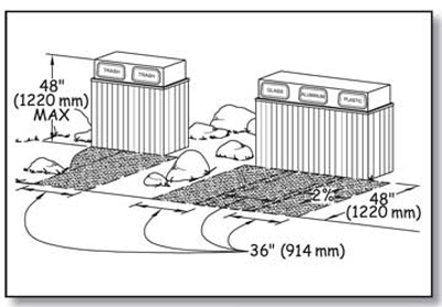
Figure 95—The requirements for trash and recycling containers.
Provide a clear floor or ground space that is either 36 inches (914 millimeters) by 48 inches (1,220 millimeters) positioned for a forward approach or 30 inches (760 millimeters) by 60 inches (1,525 millimeters) positioned for a side approach to the receptacle opening at each container. The clear space may overlap the clear space for adjacent containers. It must be adjacent to and may overlap the outdoor recreation access route. The slope of the clear space must not be steeper than 1:48 (2 percent) in any direction. When the surface is unpaved or not built with boards, slopes not steeper than 1:33 (3 percent) are allowed if necessary for drainage. Ensure the surface is firm and stable and made from a material consistent with the setting and level of development. However, if a condition for exception in an alteration project at an existing site prohibits full compliance with a specific requirement for clear floor or ground space (surface, slope, size, or location), the clear floor or ground space only has to comply with requirements to the extent practicable.
Ensure controls and operating mechanisms for containers comply with the technical requirements for reach ranges and operability specified in ABAAS, sections 308 and 309, and explained in "Reach Ranges and Operability Requirements" of this guidebook.
An exception is allowed for lids and operating controls designed to deter large animals, such as grizzly bears (figure 96). Large animals pose a threat to humans when they become accustomed to wandering through recreation sites in search of food. Most containers equipped with accessible controls and operating mechanisms can be opened by determined bears. Containers in recreation areas where bears and other large animals pose a risk to humans don't have to comply with accessibility provisions for operating controls until accessible bear-proof containers are available from more than one source. Dumpster type trash and recycling receptacles are not required to comply with the operability requirements.

Figure 96—Grizzly bears have the power and persistence to get food that is not secured properly.
Telescopes and Periscopes
Viewing areas are sometimes equipped with mounted telescopes or periscopes to provide the visitor with a better view of a point of interest. Whenever a telescope or periscope is provided, ensure that a separate telescope or periscope is available for use from a standing position (60 inches above the floor or ground surface is suggested) and from a seated position at each distinct viewing location. This allows all visitors to experience views similarly. Telescopes and periscopes that are usable from a seated position will provide the widest range of viewing opportunities for seated individuals, as well as children and people of short stature. The telescopes or periscopes at each location can be mounted separately or on the same pedestal. Telescopes or periscopes for use from a seated position must be connected to the other major constructed features at the recreation area by an outdoor recreation access route and meet the following requirements.
Ensure that controls and operating mechanisms for telescopes and periscopes usable from a seated position comply with the technical requirements for reach ranges and operability specified in ABAAS, sections 308 and 309, as explained in "Reach Ranges and Operability Requirements” of this guidebook. The eyepiece of each telescope or periscope usable from a seated position must be 43 inches (1,090 millimeters) minimum and 51 inches (1,295 millimeters) maximum above the floor or ground surface. Although not required, an adjustable scope mount is ideal for accessible viewing. Figure 97 shows one way to configure an accessible telescope area.
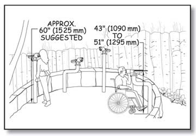
Figure 97—Requirements for viewing areas with telescopes and periscopes.
Provide a clear floor or ground space that is adjacent to (and may overlap) an outdoor recreation access route at all accessible telescopes and periscopes so that someone using a wheelchair or other assistive device can approach and move around them. This maneuvering space must be at least 36 inches by 48 inches (915 millimeters by 1,220 millimeters). Position the clear floor or ground space for a forward approach to the telescope or periscope and so that the eyepiece of the telescope or periscope is centered on the space. Provide knee and toe clearance complying with ABAAS, section 306, under the telescope or periscope (figure 98). Knee space under the telescope or periscope must be at least 30 inches (760 millimeters) wide, 19 inches (485 millimeters) deep, and 27 inches (685 millimeters) high, as measured from the ground or floor to the bottom of the structure that supports the telescope or periscope. Toe clearance of at least 9 inches (230 millimeters) above the ground or floor must extend at least an additional 6 inches (150 millimeters) beyond the required knee clearance.
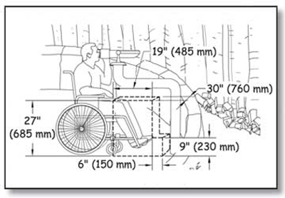
Figure 98—Requirements for knee and toe space at telescopes and periscopes.
Utilities at Recreation Sites
In general, connect electricity hookups, drinking water faucets, outdoor rinsing showers, utility sinks, sewer hookups, and other utilities that are provided in recreation sites to the other major constructed features at the recreation area by an outdoor recreation access route and ensure they meet the following requirements. However, if a condition for exception in an alteration project at an existing site prohibits full compliance with a specific requirement for clear floor or ground space (surface, slope, size, or location), the clear floor or ground space only has to comply with requirements to the extent practicable.
Ensure controls and operating mechanisms for utilities comply with the technical requirements for reach ranges and operability specified in ABAAS, sections 308 and 309, which are explained in "Reach Ranges and Operability Requirements” of this guidebook. Sewage hookups don't have to comply with the reach ranges of ABAAS, section 308 or operation requirements of section 309, but the slope and surface requirements must still be met.
Provide a clear floor or ground space of at least 30 by 60 inches (760 by 1,525 millimeters) oriented for front or parallel approach to all usable sides of utilities, except at water hydrants and outdoor rinsing showers. Hydrants and showers have their own requirements that are explained after this section. One full side of the clear floor or ground space around utilities must be adjacent to or overlap the outdoor recreation access route. The clear space also may overlap adjacent clear spaces. Figures 99 and 100 illustrate this requirement.
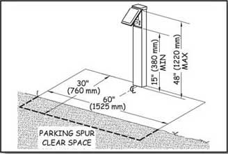
Figure 99—This illustration of an electrical connection shows the requirements for campground utilities.
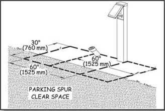
Figure 100—The clear space for utilities can overlap at campsites.
Ensure the slope of the clear space required at utilities and water hydrants does not exceed 1:48 (2 percent) in any direction. When the surface is unpaved or not built with boards, grades up to 1:33 (3 percent) are allowed if needed for proper drainage. The surface of the clear space must be firm, stable, and made of a material that is appropriate to the level of development and setting.
Ensure openings in the surface of the clear floor or ground spaces are not big enough to allow passage of a sphere more than a half of an inch (13 millimeter) in diameter. Place elongated openings more than a quarter of an inch wide with the long dimension perpendicular to the primary direction of travel.
Water Hydrants
Water hydrants, including water faucets on posts and handpumps are the outdoor devices from which people obtain drinking water. The opening where the water discharges is called a water spout. Locate water spouts between 28 inches (710 millimeters) and 36 inches (915 millimeters) above the ground or floor surface on the edge of a clear space that is at least 72 inches (1,830 millimeters) by 48 inches (1,220 millimeters). This clear space must be located with its long side adjoining (and may overlap) an outdoor recreation access route, trail, beach access route, or another clear ground space. This permits a forward or parallel approach to the water spout and allows enough room for someone in a wheelchair to turn around and leave. Locate water spouts 11 inches (280 Applying the Forest Service Outdoor Recreation Accessibility Guidelines 68 Constructed Features in Recreation Sites millimeters) [sic] minimum and 12 inches (305 millimeters) maximum from the rear center of the long side of the clear space. The requirements for the surface and slope of the clear space are the same as for other utilities.
If the water hydrant is an unusual design with the handle and spout on different sides of the post, be sure that people can access both sides. In addition, if drainage grates are provided, ensure that the openings in the grates comply with the outdoor recreation access route provision for openings. Figure 101 illustrates these requirements.
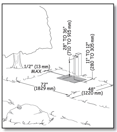
Figure 101—The requirements for water hydrants.
Standard handpumps require a force greater than 5 pounds (2.2 newtons) and a long reach to operate. Until handpumps that meet the accessibility standard for operating controls while adequately accessing the water supply are available from more than one source, handpumps are exempt from the requirements for reach ranges and operability in ABAAS, sections 308 and 309.4.
The Forest Service's technology and development program has produced an accessible handpump that can be used when a well is 40 feet (12 meters) deep or less. This pump should be considered for new or replacement shallow well installations when the accessible pump meets the technical specifications for the water supply. A deeper well pump is under development. Information about the commercially manufactured accessible handpumps (figure 102) is available on the Forest Service's internal computer network at http://fsweb.mtdc.wo.fs.fed.us/programs/eng/handpump.htm or on the World Wide Web at http://www.fs.fed.us/recreation/programs/accessibility.
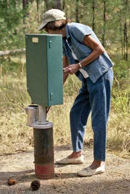
Figure 102—An accessible handpump developed by the Missoula Technology and Development Center.
Clean water tests, energy efficiency, and accessibility compliance can be achieved at most locations using solar powered pumps. The Superior National Forest in northern Minnesota (see figure 18) and the Okanogan-Wenatchee National Forest in eastern Washington (figure 103) are among the forests that have successfully used solar pump systems for a number of years in campgrounds and picnic areas of all sizes. The water spout control for solar pumps easily can be designed to require 5 pounds (2.2 newtons) of pressure or less using one closed fist (figure 104) to provide a sustainable flow of accessible water.
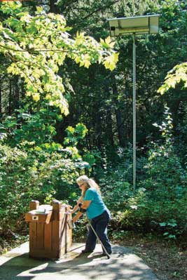
Figure 103—Solar water pumps and batteries can be housed in small pedestal enclosures and powered by solar panels on an adjacent pole.
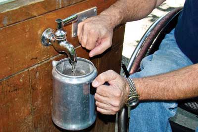
Figure 104—A solar pump provides pressure for this water spigot. A camper uses accessible controls to fill his coffee pot.
Outdoor Rinsing Showers
Outdoor showers permit people to rinse off sand, dirt, and debris. They are not intended for bathing. They generally don't offer privacy, and people usually are not permitted to disrobe when using them.
If outdoor rinsing showers are provided in a recreation site, provide at least one hand-held shower spray unit with a hose 59 inches (1,500 millimeters) long minimum. The hand-held shower spray must have at least one fixed position located 15 inches minimum (380 millimeters) and 48 inches (1,220 millimeters) maximum above the clear ground space. Because hand-held showerheads are vulnerable to vandalism and breakage, they are not a durable design choice for some recreation sites. In these cases, provide a low shower accessible to someone in a seated position and a high shower accessible to someone who is standing (figure 105). Both showers must meet the clear floor and ground space and outdoor recreation access route requirements that follow. For a low outdoor rinsing shower, mount a fixed showerhead 48 inches (1,220 millimeters) above the ground or floor. For a high outdoor rinsing shower, mount a fixed showerhead at least 72 inches (1,830 millimeters) above the ground or floor. If self-closing controls or operating mechanisms are used, the controls must remain open for at least 10 seconds.
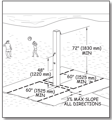
Figure 105—The requirements for outdoor rinsing showers.
Each accessible outdoor rinsing shower must have a clear floor or ground space at least 60 inches by 60 inches (1,525 millimeters by 1,525 millimeters). Locate the clear space so that the shower pedestal or wall to which the showerhead is attached is at the center back of the clear space so that the water from the showerhead is directed toward the center of the clear space. The requirements for surface, slope, and openings in the clear space are the same as for other utilities. Accessible outdoor rising showers must be connected to the area's other major features by an outdoor recreation access route.
Utility Sinks
A utility sink is deeper than a standard restroom basin or kitchen sink and can be used to clean large pots or equipment. Usually, utility sinks are provided only in highly developed recreation areas. If utility sinks are provided in a recreation facility that also contains a cook top or conventional range, at least 5 percent (but not less than 1) in each accessible room or space must comply with the following requirements. Utility sinks don't have to comply with these requirements if they're located in a space without a cook top or range.
Ensure that the height of the counter or rim surrounding the utility sink is not more than 34 inches (865 millimeters) above the ground or floor space and that the bottom of the bowl is at least 15 inches (380 millimeters) above the ground or floor space. The requirements for surface, slope, and openings in the clear space are the same as for other utilities.
If hot water is provided, wrap or shield the pipes to prevent someone from accidentally coming in contact with hot pipes. Ensure that sink controls and operating mechanisms comply with the technical requirements for reach ranges and operability specified in ABAAS, sections 308 and 309, and that water spouts are 28 inches (710 millimeters) to 36 inches (915 millimeters) above the ground or floor. Figure 106 illustrates these requirements.
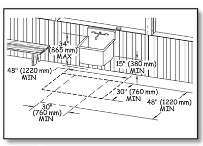
Figure 106—The requirements for utility sinks.
Buildings in Recreation Sites
Permanent buildings with walls, roof, and a door at recreation areas must meet all the applicable provisions of ABAAS, as well as those of other applicable building codes.
However, some buildings are only found in the outdoor recreation environment, such as camp shelters and pit toilets. Accessibility requirements for those buildings are explained below.
Camp Shelters
Camp shelters are small structures typically enclosed on three sides with a roof or overhang. They are often located on trails. Figure 107 shows a typical camp shelter that provides some protection from the weather. Camp shelters aren't cabins. Cabins are typically fully enclosed and must comply with ABAAS, section 806 for transient lodging.

Figure 107—The entrance to the Three Lakes camp shelter at the Tongass National Forest is level with the ground.
Ensure that each camp shelter meets the following requirements, except in two circumstances. If a condition for an exception prohibits full compliance with a specific technical requirement in FSORAG, section 5.1, the camp shelter only has to comply with the specific requirement to the extent practicable. When more than two camp shelters are grouped together in a camping unit, only 20 percent of them (but never less than two) are required to meet the requirements. For example, if five camp shelters are grouped, 20 percent is one shelter. Because of the minimum number required, however, this group must include at least two shelters that meet the requirements. However, in a group of 15 shelters, 20 percent is 3 shelters. At the least, three shelters must meet the requirements. Remember that the requirements are minimums, and the Forest Service commitment to universal design dictates that as many shelters as is practicable should meet the requirements.
Connect camp shelters located on trails to the other constructed features at the site by a trail that meets the technical requirements in FSTAG. Connect camp shelters that are located in a campground and are not on a trail to other constructed features in the camping unit and to the common use features that are provided at the campground, such as toilets, showers, water hydrants, garbage receptacles, parking spaces, and beach access by an outdoor recreation access route.
Provide a clear floor or ground space at least 36 inches (915 millimeters) by 48 inches (1,220 millimeters) at the entrance to the camp shelter. The long side of the clear floor or ground space must be parallel to the camp shelter entrance. One full, unobstructed side of the clear ground space must adjoin or overlap the trail or outdoor recreation access route (as applicable) or another clear ground space. When a condition for an exception prohibits full compliance with the clear ground requirement, the clear ground space only has to comply to the extent practicable.
Ensure that the surface of the clear floor or ground space at the open entrance side of the shelter and the floor of the shelter is firm, stable, and does not slope more than 2 percent (1:48) in any direction. However, when the surface is unpaved or not built with boards, slopes 5 percent (1:20) or less are allowed if necessary for drainage.
When the floor at the entrance to the camp shelter is raised above the ground, ensure that the floor is 17 inches (430 millimeters) minimum to 19 inches (485 millimeters) maximum, higher than the adjoining clear space at the open entrance side (figure 108). This height must be maintained for a length of at least 48 inches (1,220 millimeters) beside the clear space so that someone using a wheelchair or other assistive device can transfer to the floor of the shelter.
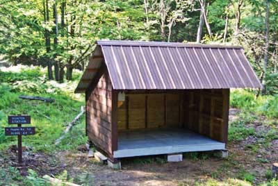
Figure 108—The entrance to the Hunter Station camp shelter at the Allegheny National Forest is raised above the ground.
If the camp shelter has a level entry, provide a turning space that is 60 inches (1,525 millimeters) minimum in diameter (see figure 62) or is T-shaped with a minimum 60- by 36-inch (1,525- by 915-millimeter) arm and a minimum 36-inch (915-millimeter) -wide by 24-inch (610-millimeter) -long base (see figure 63) inside the camp shelter. This requirement is the same as ABAAS, section 304.3. The clear space and turning space allows someone using a wheelchair or other assistive device to approach and move about the camp shelter.
The floor surface within the camp shelter must be firm and stable and must not slope more than 2 percent (1:48) in any direction. If amenities such as tables or wood stoves are provided in camp shelters, they must meet the requirements of FSORAG, section 5.
Toilet Buildings and Pit Toilets
Toilet buildings are provided for visitor convenience and comfort in recreation sites that meet the criteria for level 3 or higher on the recreation site development scale. Vault toilets, flush toilets, or composting toilets are typical at these sites. Regardless of the waste disposal system or design of the building, make sure they meet the requirements of ABAAS. Specifically, toilet buildings at developed recreation sites with only one riser must comply with the requirements for toilet room size and clearances in section 603 of ABAAS and with the requirements for toilet seats, grab bars, controls, and dispensers in sections 604.4, 604.5, 604.6, and 604.7 of ABAAS. Toilet buildings with multiple risers must comply with all of section 604 of ABAAS. If washing sinks, showers, or other amenities are provided in toilet buildings, or separate changing or shower buildings, they must also comply with the appropriate sections of ABAAS. When designing toilet buildings, be careful not to confuse the requirements for toilet stalls with those for single riser toilet rooms.
Pit toilets are located in remote areas. They are provided primarily for resource protection, rather than for visitor convenience and comfort. Pit toilets are primitive outhouses that may consist simply of a hole dug in the ground covered by a toilet riser (figure 109). The pit toilet riser may or may not be surrounded by walls and may or may not have a roof. Pit toilets may be permanent installations or they may be moved from one location to another as the hole is filled or the area has become overused. Waste disposal in pit toilets may be directly into the ground (pit) or may include moldering or composting processes.
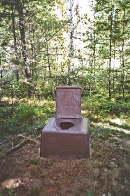
Figure 109—A fiberglass riser for a pit toilet in the Boundary Waters Canoe Area.
Do not confuse pit toilets with toilet buildings. Pit toilets are only provided in low development areas where it has been determined that they are necessary for resource or environmental protection. Pit toilets are never appropriate in a Forest Service recreation site with a development scale level of 3 or higher.
Ensure each pit toilet meets the following requirements and is connected to the area's other major constructed features by an outdoor recreation access route. Connect pit toilets that are provided on trails to the area's other major constructed features by a route that complies with the trail specifications rather than an outdoor recreation access route.
The design of pit toilets varies widely depending on the setting, the amount of expected use, and the system used to manage the waste. If an accessible pit toilet has walls, a floor, a door, or a roof, these components must comply with the appropriate provisions of ABAAS as follows.
If the pit toilet has a riser and toilet seat, ensure that the total height of that seat and the riser it rests on is 17 to 19 inches (430 to 485 millimeters) above the ground or floor.
If the pit toilet has lightweight privacy screens or has no walls, ensure that the riser has vertical or nearly vertical sides and a flat area on each side of the seat that is about 3 inches (75 millimeters) wide.
For pit toilets with lightweight privacy screens or no walls, provide a clear floor or ground space that is at least 60 inches (1,525 millimeters) wide and 56 inches (1,420 millimeters) deep. Of the required width of clear floor space, ensure that only 16 to 18 inches (405 to 455 millimeters) is on one side of the centerline of the riser; the rest must be on the other side. The depth of the clear space is measured from the back of the riser and extends in front of the riser (figure 110). If these clear space requirements can't be met due to a condition for an exemption, then the clear space must meet the technical requirements to the extent practicable.
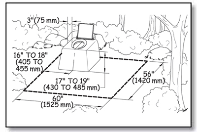
Figure 110—The requirements for clear space at an unenclosed toilet.
If there are sturdy walls around the pit toilet riser, standard riser dimensions, placement, and grab bars are required as shown in ABAAS, sections 603, 604, and 609. Grab bar size, strength, finish, and position requirements are explained in "Grab Bars" of this guidebook.
Grab bars must comply with the reach ranges required in ABAAS, section 308, and explained in "Reach Ranges and Operability Requirements" of this guidebook. As required in ABAAS, section 604.5, grab bars for toilets must be installed in a horizontal position, 33 to 36 inches (840 to 915 millimeters) above the finished floor, measured to the top of the gripping surface.
Ensure the grab bar beside the riser is at least 42 inches (1,065 millimeters) long, is located no more than 12 inches (305 millimeters) from the wall behind the toilet, and extends at least 54 inches (1,370 millimeters) from the rear wall. The grab bar behind the riser must be at least 36 inches (915 millimeters) long and extend from the centerline of the water closet at least 12 inches (305 millimeters) on the side closest to the side wall grab bar and at least 24 inches (610 millimeters) on the other side (figure 111).
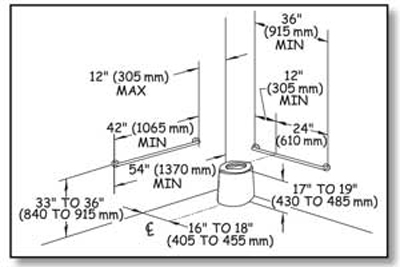
Figure 111—The grab bar placement requirements for pit toilets enclosed by walls.
For pit toilets enclosed by walls, make sure the back of the riser is against the wall behind the riser. Provide a clear floor space that is at least 60 inches (1,525 millimeters) wide and 56 inches (1,420 millimeters) deep around the toilet.
Of the required width of clear floor space, ensure that only 16 to 18 inches (405 to 455 millimeters) on one side of the centerline of the riser, and the rest is on the other side. Provide turning space of at least 60 inches (1,525 millimeters) in diameter or T-shaped with a minimum 60- by 36-inch (1,525- by 915-millimeter) arm and a minimum 36-inch (915-millimeter) -wide by 24-inch (610-millimeter) -long base. This requirement is the same as ABAAS, section 304.3. Portions of the turning space may overlap the toilet clear floor space (figure 112).
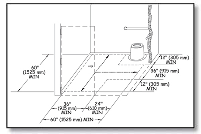
Figure 112—The requirements for a T-shaped turning space for a pit toilet enclosed by walls.
When there are walls, ensure doorways or wall openings that provide entrance to the toilet have a minimum clear width of 32 inches (815 millimeters), in compliance with ABAAS, section 404.2.3. Door swings must not obstruct the clear floor space inside the pit toilet. Doors that open out or slide use space efficiently to provide the required interior clear space, but they are not allowed to block the access route to the building. Ensure door hardware, such as handles, pulls, latches, and locks, complies with the technical requirements for reach ranges and operability specified in ABAAS sections, 308 and 309 and explained in "Reach Ranges and Operability Requirements."
Construction Tip
Do not use grab bars with privacy screens.
Lightweight privacy screens are sometimes provided for pit toilets in remote general forest areas. Screens may be provided in areas where vegetation or terrain doesn't provide enough privacy but where walls or sturdier enclosures would significantly change the recreational setting or adversely impact significant natural features or where it is difficult and expensive to pack in conventional construction materials. These screens may be made from tent fabric or other lightweight materials and have only enough structural strength to stay upright.
Never attach grab bars to privacy screens. Screens do not have enough strength to support a 250-pound (1,112-newton) load on the grab bars. Instead, position the screens outside the clear area required around the toilet to allow unobstructed access to the toilet area.
Design Tip
Edge protection may be used for inclines in outdoor recreation environments.
Edge protection is a raised curb, wall, railing, or other structure that defines the edge of a travel surface and helps keep people on the travel surface. Edge protection is not required for accessibility, and it is not usually desirable in outdoor environments. However, edge protection may be desirable for safety or other reasons; it should be a little higher in an outdoor environment than in an urban environment. It isn't as easy to see or detect objects near the ground in an outdoor environment, so edge protection curbs should be at least 3 inches (76 millimeters) high (see figure 46).
Whether the pit toilet has walls or not, make sure the slope of the turning space and the clear floor or ground space does not exceed 1:48 (2 percent) in any direction. When the surface is unpaved or not built with boards, grades 1:33 (3 percent) or less in any direction are allowed if required for proper drainage. Provide a surface that is firm, stable, and made from material appropriate to the setting and level of development. When there is a condition for an exception that prohibits full compliance with the slope or surface requirements, they only have to be met to the extent practicable.
Locate the entrance to each pit toilet at ground level wherever possible. For instance, composting and moldering toilets have a "basement" area where waste is processed. The need to service the area under the riser may make it difficult to provide a ground level entrance to the toilet. In other areas, surface bedrock, permafrost, or other ground conditions make it difficult to dig a pit. In situations where the pit toilet is elevated above the ground surface, make sure any inclined access from the connecting outdoor recreation access route or trail to the entrance of the toilet structure is firm and stable, at least 36 inches (915 millimeters) wide, and not more than a 1:12 (8.33 percent) slope to the extent practicable. If an inclined connection meeting these requirements isn't practicable because of a condition for exception, steps are permitted—but only as a last resort. Provide a landing at least 60 inches by 60 inches (1,220 millimeters by 1,220 millimeters) outside the entrance door to the toilet structure. Because it is an outdoor recreation environment, make sure the inclined surface is firm and stable. It doesn't have to be slip-resistant, and handrails aren't required.
Getting to the Water—Beach Access Routes
Beach access routes allow pedestrians to get across the beach so they can play, swim, or participate in other beachrelated [sic] activities. A beach access route is a continuous unobstructed path that crosses the surface of the beach and provides pedestrian access to the water. Section 6 of FSORAG explains the requirements for beach access routes. Because beach access routes and outdoor recreation access routes perform similar functions, the requirements are similar.
Beaches are grouped into three general types:
-
Tidal beaches (figure 113)
-
River beaches (figure 114)
-
Lake, pond, and reservoir beaches (figure 115)
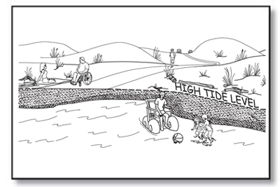
Figure 113—The high tide level at a coastal beach.
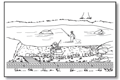
Figure 114—The mean high water level at a river.

Figure 115—The normal recreation water level at a lake.
Beach access routes must extend from an outdoor recreation access route or other beach entry point to the high tide level at tidal beaches, mean high water level at river beaches, and the normal recreation water level at lake, pond, and reservoir beaches.
Beach access routes are required when dune crossings, stairways, or ramps leading from boardwalks to the beach are constructed or altered; when parking facilities, pedestrian routes, toilet facilities or bathing facilities that serve the beach are constructed or altered; or when a beach nourishment project is undertaken. They must coincide with or be located in the same area as other pedestrian access to the beach. Employ universal design wherever possible so that all visitors use the same route to get to the water (figure 116).
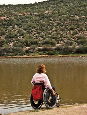
Figure 116—Everybody ought to be able to get to the beach.
When beach access routes are required, provide them for each half mile of managed shoreline. However, the number of beach access routes doesn't have to exceed the number of pedestrian beach access points that are provided. Beach access routes are not required where pedestrian access to the beach is not allowed. Beach access routes associated with beach nourishment projects are only required up to an expenditure of 20 percent of the costs of the beach nourishment project.
Removable beach access routes can be moved to a protected storage area during storms and other periods when the routes are subject to damage. Removable beach access routes are not required to comply with the slope and resting interval technical requirements. Use temporary beach access route surfaces as necessary where restrictive permits are required in coastal and shoreline areas where seasonal tides or high flows would remove a permanent structure, or in areas where the beach erodes or builds up each season, quickly turning a permanent beach access route into a hazard. Vehicular access or access provided by an assistive device isn't an acceptable temporary beach access route.
Design Tip
Extend beach access routes to a reasonable point on the beach.
Access to the water at tidal beaches will vary considerably depending on geographic locations because the difference between low and high tides will vary from place to place. For example, a beach in Alaska may experience tidal differences of up to 30 feet (9 meters); beaches in Florida will have much smaller differences between the tides. The high tide mark is a reasonable location to stop constructed features; they are much more likely to wash out below this point. The same general guidance applies to mean high water level at rivers and the normal recreation water level at lakes.
In some locations, it may make sense to continue the beach access route below the mean high water level or normal recreation water level. In locations with significant variations in water level through the recreation season, visitors appreciate extended access routes where they can be constructed (figure 117).
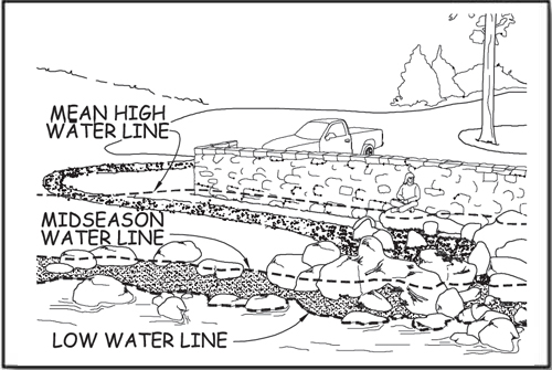
Figure 117—Some beach access routes are partly inundated every year.
Exceptions to the Guidelines That Apply to Beach Access Routes
When a condition for an exception prohibits full compliance with a specific technical requirement on a portion of a beach access route, that portion of the beach access route must still comply with the requirement to the extent practicable. (See "Using the Conditions for an Exception in FSORAG.") Document the reason that full compliance wasn't achieved and file it with the project records for the construction or alteration project.
Notifying the U.S. Access Board About Exemptions
Infrequently, an entire beach access route must be exempted from the technical requirements because extreme or numerous conditions for exemptions make it impractical to provide a route that meets the requirements. In these cases, document the reason for the exemption, the date of the decision, and the names of the individuals who made the decision. Retain documentation with the records for the construction or alteration project. Notify the U.S. Access Board of the determination and the reason for that decision. Contact information for the U.S. Access Board is available at http://www.access-board.gov/
The U.S. Access Board has drafted a form that may be used to document and submit an exemption decision. The form will be available at http://www.access-board.gov/guidelines-and-standards/recreation-facilities/outdoor-developed-areas when the U.S. Access Board final guidelines are published.
Surface and Clear Tread Width on Beach Access Routes
A beach access route must have a firm, stable surface, and have a clear tread width of 60 inches (1,525 millimeters) minimum.
Slopes and Resting Intervals for Beach Access Routes
Running slope, also referred to as "grade," is the lengthwise slope of a beach access route, parallel to the direction of travel. Sections of beach access route of any length are allowed to have a running slope ratio of up to 1:20 (5 percent grade) (see figure 37). Steeper terrain may make this slope difficult to achieve. Many visitors can negotiate steeper slopes for short distances, so running slopes up to 1:12 (8.33 percent) are permitted for up to 50 feet (15 meters), and running slopes of up to 1:10 (10 percent) are permitted for up to 30 feet (9 meters). To ensure that the beach access route isn't designed as a series of steep segments, no more than 15 percent of the total length of the beach access route may exceed a slope of 1:12 (8.33 percent), as shown in table 4.
Table 4—Beach access route running slope and segment length.
| Running Slopes on Beach Access Routes | Maximum Length of Segment Between Resting Intervals | |
|---|---|---|
| Steeper than | But not Steeper than | |
| 1:20 (5 percent) | 1:12 (8.33 percent) | 50 feet (15 meters) |
| 1:12 (8.33 percent) | 1:10 (10 percent) | 30 feet (9 meters) |
Cross slopes—the side-to-side slope of a beach access route—are not allowed to exceed 1:33 (3 percent, see figure 37). When the surface is paved or is built with boards, the cross slope is not allowed to be steeper than 1:48 (2 percent).
Resting intervals are relatively level areas that provide an opportunity for people to catch their breath before continuing along the beach access route. These intervals are required between each segment of the beach access route any time the running slope exceeds 1:20 (5 percent). A resting interval must be at least 60 inches (1,525 millimeters) by 60 inches (1,525 millimeters).
The slopes of a resting interval are not allowed to exceed 1:33 (3 percent) in any direction. When the surface is paved or is built with boards, the slope is not allowed to be steeper than 1:48 (2 percent) in any direction.
Tread Obstacles on Beach Access Routes
Tread obstacles on a beach access route must not be more than 1 inch (25 millimeters) high. When the surface of the beach access route is paved or is built with boards, tread obstacles must not be more than a half of an inch (13 millimeters) high. Where possible, ensure obstacles on beach access routes are separated by at least 48 inches (1,220 millimeters) so people who use wheelchairs can maneuver around the obstacles.
Openings in Beach Access Routes
Openings are gaps in the surface of a beach access route. Gaps include spaces between the planks on a boardwalk and drainage holes in temporary or permanent surfaces. Openings that are big enough to allow wheels, cane or crutch tips, or shoe heels to drop through or get stuck are hazards that shouldn't exist in pedestrian routes. Openings up to a half of an inch (13 millimeters) wide are permitted. Place elongated openings more than a quarter of an inch wide with the long dimension perpendicular or diagonal to the primary direction of travel (see figure 44).
Protruding Objects on Beach Access Routes
Outdoor accessibility guidelines define protruding objects as constructed features such as signs that extend into the clear width area of a beach access route or resting interval and are between 27 inches (685 millimeters) and 80 inches (2,030 millimeters) above the travel surface. Do not allow constructed features to extend more than 4 inches (100 millimeters) into the clear width area (see figure 45). Constructed features that extend into the travel way of a beach access route from the side or from overhead can be hazardous to people who are paying more attention to their companions than the travel route, as well as to people who are blind or have low vision.
Accessibility guidelines do not consider natural elements such as tree branches and rock formations to be protruding objects. Provide and maintain clearance from natural elements around beach access routes in accordance with your unit's standards; keep in mind overhanging hazards to people who are blind or have low vision or are not focused on the route ahead.
Elevated Dune Crossings
An dune crossing that is elevated or has a slope that exceeds 1:20 (5 percent) that is part of a beach access route must have handrails and edge protection (figure 118). Locate handrails continuously along both sides of the dune crossing at a height of 34 inches (865 millimeters) to 38 inches (965 millimeters) above the walking surface. Ensure the handrails are easy to grip and comply with all the other requirements in ABAAS, section 505. Provide a curb or barrier directly under the handrail that would prevent a 2-inch (50-millimeter) sphere on, or up to 2 inches (50 millimeters) above, the dune crossing surface from rolling under the handrail. The clear width of elevated dune crossings may be narrower than the rest of the beach access route, but must be at least 48 inches (1,220 millimeters). Resting intervals are not required on elevated dune crossings. Consider including resting intervals similar to those for outdoor recreation access routes if the elevated crossing is steeper than 1:20 (5 percent).
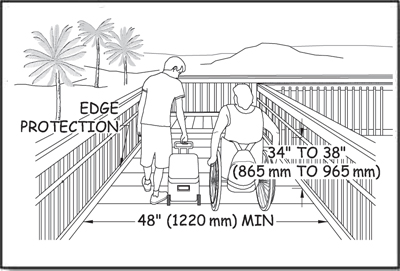
Figure 118—The requirements for width, handrails, and edge protection onan elevated beach access route.
Gates and Barriers on Beach Access Routes
If gates or barriers are constructed to control access to beach access routes, include openings wide enough to allow hiker passage. Refer to the FSORAG for the technical provisions for gates and barriers. These requirements are also explained in "Getting From Here to There—Outdoor Recreation Access Routes" of this guidebook.
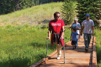
User Comments/Questions
Add Comment/Question