
Forest Service Outdoor Recreation Accessibility Guidelines
(FSORAG)
2013
All Facilities and Features Addressed in the FSORAG that are Constructed or Altered Within the National Forest System shall comply with the FSORAG.
_______________________________________________________________
Contents
FSORAG - Technical Provisions:
Contains the definitions and technical requirement specifications.
Appendix:
Provisions of the Architectural Barriers Act Accessibility Guidelines that are referenced in the FSORAG Technical Provisions
1.0 APPLICATION
The Forest Service Outdoor Recreation Accessibility Guidelines (FSORAG) and the Forest Service Trail Accessibility Guidelines (FSTAG) are the legally enforceable standards for use on the National Forest System for the facilities and features addressed in those guidelines. They have been updated to incorporate the supplement to the Architectural Barriers Act Accessibility Standards, the Outdoor Developed Area Accessibility Guidelines (ODAAG), developed by the Architectural and Transportation Barriers Compliance Board (U.S. Access Board).
While they incorporate the U.S. Access Board’s ODAAG they also ensure the application of equivalent or higher guidelines, in order to comply with other existing Forest Service policies, including universal design, as well as agency terminology and processes.
The FSORAG and FSTAG became the National Forest System’s legal standard for all applicable facilities on May 26, 2006 with the final Federal Register publication of Forest Service Manuals 2330 and 2350. As stated in the Federal Register, these guidelines will be updated periodically to ensure they remain equal to or a higher standard than other guidelines and standards applicable to Federal agencies under the Architectural Barriers Act.
The FSORAG provides guidance for maximizing the accessibility of outdoor recreation areas in the National Forest System, while protecting the unique characteristics of their natural setting.
All facilities and features addressed in the FSORAG that are constructed or altered within the National Forest System shall comply with the FSORAG. Such facilities include but are not limited to camping facilities, picnic areas, viewing areas at overlooks, beach access routes, outdoor recreation access routes, and other constructed features associated with outdoor recreation areas in the National Forest System.
Construction or alteration of all facilities within the National Forest System that are not addressed in the FSORAG or FSTAG shall comply with the applicable requirements of the Architectural Barriers Act Accessibility Standards (ABAAS).
Trails within the National Forest System shall comply with the Forest Service Trail Accessibility Guidelines (FSTAG), which are available at http://www.fs.fed.us/recreation/accessibility/
Boating and fishing facilities, swimming pools, play areas, sports arenas, miniature golf courses, and amusement parks, which are referred to as "recreation facilities" are addressed in Chapter 10 of the ABAAS (http://www.access-board.gov).
These guidelines do not apply to maintenance work (routine or periodic repair of existing trails, recreation sites, or facilities).
Where existing individual site furnishings are altered or replaced, the floor or ground surface under or around them is not required to be altered solely because an accessible furnishing has been placed in that site. While the new or altered furnishing must be accessible the clear floor or ground space shall not be required to comply with surface and slope requirements until the surface and slope alteration is the focus of work in that site.
1.1 Conditions for an Exception.
Where one or more of the following conditions exists in an outdoor recreation area, an "exception" provided in the guidelines for that specific technical requirement can be used where that condition exists. The exception shall not be used on the portion of the feature where the condition does not exist. If no exception is provided for the technical requirement, no exception is allowed. All other appropriate design options should be considered before applying the exception.
Condition for an Exception 1. Where compliance with the technical provision is not practicable due to terrain.
Condition for an Exception 2. Where compliance with the technical provision cannot be accomplished with the prevailing construction practices.
Condition for an Exception 3. Where compliance with the technical provision would fundamentally alter the function or purpose of the facility or the setting.
Condition for an Exception 4. Where compliance is precluded by the:
-
Endangered Species Act (16 U.S.C. §§ 1531 et seq.);
-
National Environmental Policy Act (42 U.S.C. §§ 4321 et seq.);
-
National Historic Preservation Act (16 U.S.C. §§ 470 et seq.);
-
Wilderness Act (16 U.S.C. §§ 1131 et seq.); or
-
Other Federal, State, or local law the purpose of which is to preserve threatened or endangered species; the environment; or archaeological, cultural, historical, or other significant natural features.
Alteration of a recreation site, building, or facility.
A change to a portion of a recreation site, building, or facility that is addressed by the accessibility guidelines and that affects or could affect the usability of the site, building, or facility. Alterations include, but are not limited to, remodeling, renovation, rehabilitation, reconstruction, historic restoration, change in surface of circulation paths or vehicular ways, changes or rearrangement of the structural parts or elements, and changes or rearrangement in the plan configuration of walls and full-height partitions. Normal maintenance, reroofing, painting or wallpapering, or changes to mechanical and electrical systems are not alterations unless they affect the usability of the building or facility.
Beach Access Route.
A continuous, unobstructed path designed for pedestrian use that crosses the surface of a beach or that leads from a pedestrian access point to the high tide level at tidal beaches; mean high water level at river beaches; or the normal recreation water level at lake, pond, and reservoir beaches.
Beach Nourishment.
A process by which sediment (usually sand) is added to a beach. An entity is not required to expend more than 20% of the costs of a beach nourishment project to provide a beach access route.
Camp Shelter.
A small structure typically enclosed on three or all four sides, with a roof or overhang. Camp shelters are often located on trails. Camp shelters are not cabins, which are typically larger and are required to comply with ABAAS section 806 for transient lodging where short term accommodations are provided.
Camping Facility.
A site, or portion of a site, developed for outdoor recreational purposes that contains camping units.
Camping Unit.
A discrete area within a campground with a persons at one time capacity (PAOT) of 5 that usually includes a camp living area, a parking spur, and one or more constructed features such as a picnic table and a cooking or campfire area.
-
Camp Living Area. The area in a camping unit that contains constructed features, such as picnic tables, grills, fire rings, utilities, and other related elements, and may be located adjacent to or near a parking spur.
-
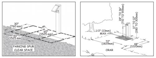
Parking Spur. The space in a camping unit that is designed for vehicular access and parking and that includes a driveway and vehicle parking area.
-
Driveway. The section of a parking spur connecting the road accessing a campground and a vehicle parking area.
-
Vehicle Parking Area. The section of a parking spur where camping vehicles, such as cars, motorcycles, vans, recreational vehicles, and trailers, are parked.
-
Multiple Camping Unit. A camping unit that can accommodate more than 5 PAOT. A double camping unit accommodates 10 PAOT. A triple camping unit accommodates 15 PAOT. A camping unit with a PAOT of 20 or more is a group camping unit.
ETA Editor's Note
Throughout this document, "PAOT" means "persons at one time."
Circulation Path.
An exterior or interior way of passage provided for pedestrian travel.
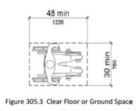
Clear Floor or Ground Space.
The minimum unobstructed floor or ground space required to accommodate a single, stationary wheelchair and occupant.
Developed Recreation Site.
A recreation site that has a development scale level of 3, 4 or 5 on the Recreation Site Development Scale in Forest Service Handbook 2309.13,10– Exhibit 01.
Essential Container.
A trash, recycling, food storage, or other animal-resistant container.
Outdoor Constructed Feature.
A constructed element provided at an outdoor recreation site such as a picnic table; fire ring; pedestal grill; tent pad; bench; trash, recycling, or other essential container; fireplace, woodstove, water hydrant or pump, telescope or periscope; pit toilet; or outdoor rinsing shower.
Outdoor Recreation Access Route (ORAR).
A continuous, unobstructed path designed for pedestrian use that connects constructed features in a campground, camping unit, picnic area, at a trailhead or other recreation site where modifications are provided for visitor convenience and comfort.
Pedestrian Access Points to a Beach.
A location developed as an entry point to the beach for pedestrians. Access Points include parking facilities that serve beaches, dune crossings, and stairways or ramps leading from boardwalks, walkways, or parking spaces to the beach.
Picnic Facility.
A site, or portion of a site, developed for outdoor recreational purposes that contains picnic units.
Picnic Unit.
An outdoor space within a picnic area or facility that is designed and constructed for picnicking and that contains one or more constructed features such as picnic tables, grills, and other related elements.
Pit Toilet.
A primitive outhouse consisting of a toilet riser over a hole dug into the ground or receptacle to receive and naturally decompose human waste. Pit toilets are provided primarily for resource protection and are only constructed at recreation sites with a Recreation Site Development Scale level of 2 of less. A pit toilet riser may or may not be surrounded by walls and may or may not have a roof. A pit toilet may be permanently installed or may be moved from one location to another as the pit is filled or the area becomes severely impacted from use. Waste may be disposed of directly into the pit or may be composted.
Practicable.
Practicable in this context means the work can be completed within the limits of the applicable Conditions for an Exception and results in a useful improvement for all.
Protruding Object.
A constructed feature such as a sign that overhangs an ORAR, beach access route, trail, resting interval, or passing space between 27 inches (685 mm) and 80 inches (2030 mm) above the travel surface. Accessibility guidelines for protruding objects do not apply to natural elements such as tree branches and rock formations. However, safety regulations or Forest Service construction and maintenance standards may define clear space and limit overhangs of natural protruding objects.
Provisions.
The sections of accessibility guidelines and standards that explain what is required for specific situations and facilities (parking, picnic tables, trails, etc.)
Recreation Site.
An area that is improved, developed, or otherwise identified for recreation and that has a development scale of 0, 1, 2, 3, 4, or 5 (See Forest Service Handbook 2309.13, Chapter 10 – Exhibit 01. [sic]
Reconstruction.
This term is not used in Federal accessibility guidelines or the FSORAG and FSTAG, even though it is used frequently by folks who work in recreation and trails. For the purposes of the FSORAG and FSTAG, actions are categorized as construction, alteration, or maintenance.
Scoping Requirement.
Specifications of where, when, and how much of a constructed features detailed in the accessibility guidelines technical requirements must be met in order to be in compliance with the guidelines.
Slope.
The incline of a surface.
-
Cross Slope. The difference in elevation from edge to edge of an ORAR, trail, or beach access route measured perpendicular to the direction of travel. This may be expressed as the percentage of change in elevation or as a ratio of vertical distance to horizontal distance. The percentage is shown in parentheses in these guidelines.
-
Running Slope (Grade). The difference in elevation of a section of an ORAR, trail, or beach access route measured parallel to the predominant direction of travel. This may be expressed as a ratio of vertical distance to horizontal distance or as the percentage of change in elevation. The percentage is shown in parentheses in these guidelines.
Surface.
The top layer of ground on a recreation site, ORAR, trail, or beach access route.
-
Firm. A firm surface resists deformation by indentations. During the planning process, firmness must be evaluated for noticeable distortion or compression during the seasons for which the surface is managed, under normally occurring weather conditions.
-
Stable. A surface is not permanently affected by expected weather conditions and can sustain normal wear and tear from the expected use(s) of the area, between planned maintenance.
Technical Requirements.
The specific numbers, conditions, and measurements that are required to be achieved (percent that must comply, dimensions, reach ranges, grades, trail width, etc.).
Tent Pad.
An outdoor space designed and constructed for setting-up and securing tents.
Tent Platform.
An outdoor space designed and constructed for setting-up and securing tents that is elevated above the ground surface.
Trail.
For purposes of the FSTAG and FSORAG, a trail is a pedestrian route developed primarily for outdoor recreational purposes. A pedestrian route provided primarily to connect elements, spaces, or facilities within a site is not a trail; it is an outdoor recreation access route (ORAR).
Trailhead.
For purposes of the FSORAG and FSTAG, a trailhead is an outdoor space that is designated by an entity responsible for maintaining or administering the trail to serve as an access point to the trail. The junction of two or more trails, or the undeveloped junction of a trail and a road, is not a trailhead.
Vehicle Parking Lot.
An area specifically intended for parking of more than two motor vehicles, usually divided into multiple designated parking spaces.
Viewing Area.
An outdoor space developed for viewing a landscape or point of interest such as a mountain range, a valley, or a waterfall.
Wheelchair.
A device, including one that is battery-powered, that is designed solely for use by a mobility-impaired person for locomotion and that is suitable for use in an indoor pedestrian area. A person whose disability requires use of a wheelchair or mobility device may use a wheelchair or mobility device that meets this definition anywhere foot travel is permitted (36 CFR 212 .1, Forest Service Manual 2353.05 and Title V, Section 508c, of the Americans with Disabilities Act).
2.1 General.
ORARs shall be provided between units and constructed features in campgrounds, picnic areas, trailheads, viewing areas, and other outdoor recreation sites. ORARs shall connect the outdoor constructed features within each recreation site and shall connect to common use features such as toilets, showers, water spouts, trash or recycling receptacles, parking spaces, and beach access routes.
-
Exception 1. ORARs shall not be required where camping facilities, picnic facilities, viewing areas, or outdoor constructed features are provided on trails. The routes connecting those facilities are to comply with the technical provisions for trails.
-
Exception 2. When an existing camping facility or unit, picnic facility or unit, trailhead, is altered or reconstructed and a condition for an exception in section 1.1 prohibits full compliance with a specific requirement in section 2 on a portion of an ORAR, that portion of the ORAR shall comply with the specific requirement to the extent practicable.
-
Exception 3. When a new viewing area is constructed, or an existing viewing area is altered or reconstructed and a condition for an exception in section 1.1 prohibits full compliance with a specific requirement in section 2 on a portion of an ORAR, that portion of the ORAR shall comply with the specific requirement to the extent practicable.
-
Exception 4. Where an element, space, or outdoor constructed feature is altered in a camping facility, picnic facility, viewing area, or trailhead but the circulation path to the altered element, space, or outdoor constructed feature is not altered, an ORAR shall not be required.
-
Exception 5. Where outdoor recreation access routes are provided within vehicular way (recreation site roadway), outdoor recreation access routes shall not be required to comply with 2.4 Slope, 2.5 Resting Intervals, and 2.6 Passing Spaces.
-
Exception 6. An ORAR is not required to connect accessible camping units to a recreational vehicle (RV) dump station if an accessible vehicle pull-up space is provided at the RV dump station.
2.2 Surface.
The surface of an ORAR shall be firm and stable. The type of surface should be appropriate to the setting and level of development.
2.3 Clear Tread Width.
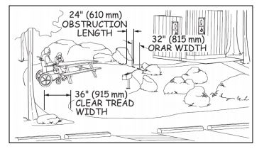
The clear tread width of an ORAR shall be at least 36 inches (915 mm).
Figure 1—The clear tread width is the unobstructed width of the traveling surface.
-
Exception 1. Where a condition for an exception in section 1.1 prevents achieving the required width, the clear tread width may be reduced to 32 inches (815 mm) minimum. If the condition for an exception prevents achieving the reduced width of 32 inches, comply to the extent practicable.
-
Exception 2. Where an ORAR is provided within a vehicular way, clear passage of 32” is required around or through speed restriction devices, gates, and other barriers on the roadway.
2.4 Slope.
The running slope (grade) and cross slope of ORARs shall comply with section 2.4.
Figure 2—The basic slope requirements for outdoor recreation access routes and beach access routes.
-
Exception: Where an ORAR is permitted to be provided within a vehicular way, the integrated ORAR shall not be required to comply with 2.4.
2.4.1 Running Slope (Grade).
The running slope (grade) of ORARs shall comply with all applicable provisions of this section.
| Running Slope (Grade) of Segment of Outdoor Recreation Access Route | Maximum Length of Segment Between Resting Intervals | |
| Steeper than | But not Steeper than | |
| 1:20 (5 percent) | 1:12 (8.33 percent) | 50 feet (15 m) |
| 1:12 (8.33 percent) | 1:10 (10 percent) | 30 feet (9 m) |
The running slope (grade) of an ORAR shall be 1:20 (5 percent) or less for any distance.
A grade of up to 1:12 (8.33 percent) is permitted for up to 50 feet (15 m) of an ORAR. Resting intervals complying with section 2.3 shall be provided at distances of no more than 50 feet (15 m) apart.
A grade of up to 1:10 (10 percent) is permitted for up to 30 feet (9 m) of an ORAR. Resting intervals complying with section 2.3 shall be provided at distances of no more than 30 feet (9 m) apart.
2.4.2 Cross Slope.
The cross slope of an ORAR shall be no more than 1:33 (3 percent). Where the surface is paved or is elevated above the natural ground, the cross slope shall not be steeper than 1:48 (2 percent).
2.5.1 Location.
A resting interval shall be provided between each ORAR segment, in compliance with section 2.4.1. Depending on the design and location, the intersection of two ORARs may act as a resting interval.
Exception. Where a vehicular way serves as the ORAR, the integrated ORAR shall not be required to comply with 2.5.
2.5.2 Length.
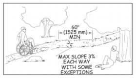
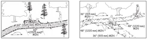
The resting interval length shall be 60 inches (1525 mm) long minimum.
2.5.3 Width.
Where resting intervals are provided within an outdoor recreation access route, resting intervals shall be at least as wide as the widest segment of the outdoor recreation access route leading to the resting interval. Where resting intervals are provided adjacent to an outdoor recreation access route, the resting interval clear width shall be 36 inches (915 mm) minimum.
2.5.4 Slope.
Resting intervals shall not be steeper than 1:33 (3 percent) in any direction. Where the surface is paved or is elevated above the natural ground, the slope shall not be steeper than 1:48 (2 percent) in any direction.
2.5.5 Turning Space.
Where resting intervals are provided adjacent to an outdoor recreation access route, a turning space complying with ABAAS section 304.3.2 shall be provided. Vertical alignment between the outdoor recreation access route, turning space, and resting interval shall be nominally level. The access route, turning space and resting interval may overlap.
2.6 Passing Spaces.
ORARs with a clear width less than 60 inches (1525 mm) shall provide passing spaces complying with 2.6 at intervals of 200 feet (61 m) maximum. Passing spaces and resting intervals shall be permitted to overlap.
Exception. Where a vehicular way serves as the ORAR, the integrated ORAR shall not be required to comply with 2.6.
2.6.1 Size.
The passing space shall be either:
A space 60 inches (1525 mm) minimum by 60 inches (1525 mm) minimum; or
The intersection of two outdoor recreation access routes providing a T-shaped space complying with ABAAS section 304.3.2 where the base and the arms of the T-shaped space extend 48 inches (1220 mm) minimum beyond the intersection. Vertical alignment at the intersection of the outdoor recreation access routes that form the T-shaped space shall be nominally level.
2.7 Tread Obstacles.
Where tread obstacles exist on the surface of an ORAR, they shall not exceed 1 inch (25 mm) in height. Where the surface is paved or is elevated above the natural ground, obstacles shall not exceed 1/2 inch (13 mm) in height measured vertically to the highest point.
2.8 Openings.
Openings in the surface of ORARs shall be small enough to prevent passage of a 1/2 inch (13 mm) diameter sphere. Where possible, elongated openings should be placed perpendicular, or as close to perpendicular as possible, to the dominant direction of travel.
2.9 Protruding Objects.
Constructed features, including signs, water sources, and so forth shall not extend into the space above an ORAR more than 4 inches (100 mm) if they are between 27 inches (685 mm) and 80 inches (2030 mm) above the surface of the ORAR.
2.9.1 Natural Elements.
Accessibility guidelines for protruding objects do not apply to natural elements such as tree branches and rock formations. However, safety regulations or Forest Service construction and maintenance standards may define clear space and limit the allowable extension of natural protruding objects over the ORAR surface.
2.10 Gates and Barriers.
Where gates or barriers are constructed to control access to an ORAR, gates and barriers shall comply with 2.10.
2.10.1 Clear Width.
Gate openings and openings in barriers for pedestrian passage shall provide a clear width of 36 inches (915 mm), complying with ODAAG, section 1017.3 Clear Tread Width.
2.10.2 Gate Hardware.
Gate hardware shall comply with operable controls requirements in ABAAS section 309.4 and 404.2.7.
3.1.1 Vehicle Parking.
All vehicle parking facilities shall comply with the applicable provisions of section 3.1.
| Number of Camping Units | Minimum Number of Accessible RV Parking Areas in units designated for Recreational Vehicles and Trailers |
| 1 | 1 |
| 2 to 25 | 2 |
| 26 to 50 | 3 |
| 51 to 75 | 4 |
| 76 to 100 | 5 |
| 101 to 150 | 6 |
| 151 to 200 | 7 |
| 201 and over | 8, plus 2 percent of the number over 200 |
Vehicle parking lots with more than 2 parking spaces that are not associated with an individual camping or picnic unit shall comply with ABAAS sections 208 and 502.
3.1.1.2 Camping and Picnic Vehicle Parking Spurs.
Where a parking spur is adjacent or attached to a picnic unit or a camping unit living area, it shall comply with section 3.3 as well as 3.1.
3.1.1.3 Recreational Vehicle Parking Areas.
Where recreational vehicle (RV) parking areas are provided at a camping facility or dump station, parking areas shall be provided for accessible RVs and trailers in accordance with Table 3.1.1.
3.1.2 Surface of Vehicle Parking Spurs.
The surface of vehicle parking spurs shall be firm and stable. The type of surface should be appropriate to the setting and level of development.
3.1.3 Slope of Vehicle Parking Spurs.
The slope of parking spurs shall comply with applicable provisions of section 3.1.3.
3.1.3.1 Slope of Vehicle Parking Areas.
The slope of vehicle parking areas shall not exceed 1:48 (2 percent) in any direction.
Exception. When the surface is not paved, slopes not steeper than 1:33 (3 percent) shall be permitted where necessary for drainage.
3.1.3.2 Running Slope (Grade) of Driveways.
The running slope of driveways shall be no more than 1:12 (8.33 percent) for no more than 50 feet (15 m).
Exception 1. A running slope of up to 1:10 (10 percent) for driveways is permitted for up to 30 feet (9 m).
Exception 2. For alteration only, not new construction, if exception 1 of section 3.1.3.2 cannot be met because one or more conditions for exception in section 1.1 exist, a running slope of no more than 1:10 (10 percent) is permitted for no more than 50 feet (15 m).
3.1.3.3 Cross Slope of Driveways.
The cross slope of driveways shall not exceed 1:33 (3 percent).
Exception. The cross slope of driveways may be no more than 1:20 (5 percent) where needed to ensure proper drainage or to transition from the running slope of a campground road.
3.1.4 Width of Vehicle Parking Areas.
The width of vehicle parking areas shall comply with applicable provisions of section 3.1.4.
3.1.4.1 Width of Non-RV Campsite Vehicle Parking Areas.
The width of vehicle parking areas shall be at least 16 feet (4880 mm).
Exception 1. Where the width of a vehicle parking area cannot be at least 16 feet (3960 mm) because one or more conditions for exception in section 1.1 exist, the width of the vehicle parking area may be reduced to no less than 13 feet 3960 mm) . Where only one or two vehicle parking areas are provided, no exception is permitted. Where three to ten vehicle parking areas are provided, no exception is permitted for two of the vehicle parking areas. Where over ten vehicle parking areas are provided, no exception is permitted for 20 percent of the vehicle parking areas.
Exception 2. Where a double camping unit is provided and two parking areas are provided to accommodate two vehicles side-by-side in an accessible parking spur, the total width of the vehicle parking area may be reduced from 32 feet (9760 mm) to 24 feet (7320 mm).
3.1.4.2 Width of RV Campsite and Dump Station Vehicle Parking Areas.
Where RV camping units or dump stations are provided, vehicle parking areas for recreational vehicles and trailers that are required to be accessible in accordance with table 3.1.1 shall be at least 20 feet (6100 mm) wide. The 20-foot width requirement applies only to the RV parking area and does not apply to the driveway of a parking spur or dump station.
Exception. Where a double camping unit or dump station is provided to accommodate two RVs or trailers side-by-side in a vehicle parking, the total width of the vehicle parking area may be reduced from 40 feet (12 m) to 36 feet (11 m).
3.2.1 General.
Where camping units are provided in a campground, section 4.0 and 5.0 shall apply to each camping unit. Camp living areas shall comply with sections 3.2. Vehicle parking spaces shall comply with section 3.1.
3.2.2 ORARs in Camping Units.
Connections shall be provided between site furnishings and constructed features in camping units as well as between accessible camping units, parking areas, and accessible common use features in compliance with section 2.0
3.2.3 Surface.
The ground surface in all camp living areas shall be firm and stable. The type of surface should be appropriate to the setting and level of development.
3.2.4 Slope.
The ground surface in all camp living areas shall have a slope of no more than 1:48 (2 percent) in any direction.
Exception. When the surface is not paved or is not elevated above the natural ground, slopes not steeper than 1:33 (3 percent) shall be permitted where necessary for drainage.
3.2.5 Camp Living Areas.
All constructed features provided in a camp living area shall comply with applicable provisions in sections 4.0 and 5.0.
Where walk-in camping is provided, an ORAR connecting the camp living area to the parking area shall be provided in accordance with section 2.0.
3.2.6 Identification of Accessible Camping Units.
Accessible camping units shall be identified at an entrance kiosk, on a bulletin board, or on a sign at the registration area of a campground. They shall not be identified using individual signs adjacent to the camp units.
Exception 1. Identification of accessible camping units is not required at campgrounds where all camping units are accessible.
Exception 2. Identification of accessible camping units is not required where camping units are assigned upon arrival or through a reservation system.
3.3.1 General.
Site furnishings and constructed features provided in picnic units shall comply with the applicable provisions of sections 4.0 and 5.0 of the FSORAG.
3.3.2 ORARs in Picnic Units.
Connections shall be provided between site furnishings and constructed features in picnic units as well as between accessible picnic units, parking areas, and accessible common use features in compliance with section 2.0.
3.3.3 Identification of Accessible Picnic Units.
Where not all picnic units are accessible, the picnic units that are accessible shall not be identified by signs at the individual units. Information on the location of accessible picnic units shall be provided on websites, in brochures, and at bulletin boards or information kiosks if available at the picnic facility.
3.4.1 General.
Where viewing areas are provided, each shall comply with section 3.4.
Exception 1. Where multiple viewing areas at overlooks are provided, at least one of each viewing opportunity for distinct points of interest shall be accessible.
Exception 2. When a new viewing area is constructed, or an existing viewing area is altered or reconstructed, if a condition for exception in section 1.1 prohibits full compliance with a specific requirement in 3.4, the viewing area shall comply with the specific requirement to the extent practicable.
3.4.2 ORARs in Viewing Areas.
Connections shall be provided between site furnishings and constructed features in viewing areas as well as between accessible viewing areas, parking areas, and accessible common use features in compliance with section 2.0.
Exception. Where a condition for an exception in section 1.1 prohibits full compliance with a specific technical requirement on a portion of an ORAR for a viewing area, that portion of the ORAR shall comply with the specific requirement to the extent practicable.
3.4.3 Unrestricted Viewing Opportunities.
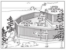
Each viewing area that is required to be accessible by section 3.4.1 shall provide at least one unrestricted viewing opportunity that accommodates eye levels between 32 inches (815 mm) minimum and 51 inches (1295 mm) maximum above the ground or floor. Where there is a drop-off of more than 30 inches (762 mm) a guard railing or barrier that complies with the height and opening requirements of the International Building Code sections 1013.2 and 1013.3 (2006 edition) shall be provided.
3.4.4 Clear Ground Space and Turning Space.
Each viewing area that is required to be accessible by section 3.4.1 shall have a clear ground or floor space 36 inches (915 mm) minimum by 48 inches (1220 mm) minimum positioned for either forward or parallel approach to the viewing location and at least one turning space that complies with section 304.3 of the ABAAS.
3.4.5 Grade.
The clear ground space and turning space required by section 3.4.3 shall have a slope of no more than 1:48 (2 percent) in any direction.
Exception. When the surface is not paved or is not elevated above the natural ground, slopes not steeper than 1:33 (3 percent) shall be permitted where necessary for drainage.
3.4.6 Surface.
The surface of each viewing area shall be firm and stable. The type of surface should be appropriate to the setting and level of development.
3.4.7 Openings.
Openings in the clear ground space and turning space surface shall not allow passage of a sphere more than 1/2 inch (13 mm) diameter. Where possible, elongated openings should be placed perpendicular, or as close to perpendicular as possible, to the dominant direction of travel.
3.4.8 Viewing Areas Accessed by Vehicular Ways.
Where a viewing area is accessed by a vehicular way and parking spaces are provided adjacent to the viewing area, the accessible parking spaces shall be connected to the viewing areas by an outdoor recreation access route complying with 2.0. The outdoor recreation access route shall connect the distinct viewing locations, accessible outdoor constructed elements, and other accessible elements, accessible spaces, and accessible facilities in the viewing area.
3.5.1 General.
Per section F216 of the ABAAS, the ISA

-
Accessible parking spaces in parking lots where there are 5 or more designated parking spaces, including accessible parking spaces.
-
VAN accessible parking spaces in lots must be signed as such.
-
RV accessible parking spaces in lots must be signed as such.
-
-
Accessible loading zones.
-
Accessible restrooms and bathing facilities.
-
If the main entrance to a building is not accessible, in the vicinity of the closest accessible entrance.
-
Accessible means of egress out of a building.
-
Accessible areas of refuge inside multi-story buildings.
In addition, the ISA may only be posted at the entrance to recreation areas with a Recreation Site Development Scale level of 3 or higher, but only where ALL constructed features within that recreation area comply with applicable provisions of the ABAAS and FSORAG.
Use of the ISA for identification of accessible camping units shall conform to 3.2.6. Use of the ISA for identification of accessible picnic units shall conform to 3.3.3.
3.5.2 Color of the ISA.
Per section 703.7 of the ABAAS, the ISA shall be posted in high-contrast colors. The ISA is not required to be blue and white when posted on Federal lands.
3.5.2.1 Enforceable Accessible Parking Spaces.
To be enforceable at accessible parking spaces, the ISA must comply with the Manual on Uniform Traffic Control Devices (MUTCD) section 2B.35, which requires the ISA to be displayed in blue and white.
3.5.2.2 Accessible Space Pavement Markings.
Where parking spaces are paved, pavement markings designating accessible parking spaces must be blue, per the MUTCD section 3A.05.
3.5.3 Signs in General.
If materials need to be obtained from or manipulated on a sign or kiosk, the sign or kiosk shall be designed to meet the reach ranges in section 308 of the ABAAS.
4.1.1 General
Where picnic tables are provided, each shall comply with section 4.1.
Exception. In alterations, where a condition for exception in section 1.1 prohibits full compliance with a specific requirement for clear floor or ground space surface slope, size, or location, the clear floor or ground space shall comply with requirements to the extent practicable.
4.1.2 Number of Wheelchair Seating Spaces.
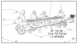
Each picnic table shall have at least one wheelchair seating space. Picnic tables shall have at least one wheelchair seating space for each 24 linear feet (7 linear m) of usable table surface perimeter as shown in table 4.1.2. Each wheelchair seating space shall comply with section 4.1.3 through 4.1.6.
| Table Top Perimeter | Typical Table Length (for 2 ft. 6 in. table width) | Number of Wheelchair Seating Spaces Required |
| Up to 24 linear ft. (7 linear meters) | Up to a 9-ft. table (3 meters) | 1 spaces |
| 24 to 48 linear ft. (7 to 15 meters) | 10- to 20-ft. table (3.1 to 6 meters) | 2 spaces |
| 48 to 72 linear ft. (15 to 22 meters) | Typically custom-built table | 3 spaces |
| 72 to 96 linear ft. (22 to 29 meters) | Typically custom-built table | 4 spaces |
| 96 to 120 linear ft. (29 to 37 meters) | Typically custom-built table | 5 spaces |
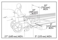
4.1.3 Wheelchair Seating Space.
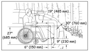
Knee space for wheelchair seating shall be at least 27 inches (685 mm) high, 30 inches (760 mm) wide, and 19 inches (485 mm) deep. Toe clearance of at least 9 inches (230 mm) in height shall extend at least an additional 5 inches (125 mm) from the knee clearance. Clear floor or ground space that is at least 30 inches by 48 inches shall be provided at each seating space that is required to be accessible and positioned for a forward approach to the table.
4.1.4 Clear Floor or Ground Space.
At least 48 inches (1220 mm) of clear floor or ground space shall surround the usable sides of a picnic table, measured from the back edge of the benches. This space may overlap the ORAR.
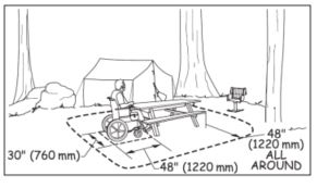
Exception. The clear floor or ground space for a picnic table may be reduced to no less than 36 inches (915 mm) where one or more conditions for an exception in section 1.1 exist.
4.1.5 Slope.
The slope of the surface of the clear floor or ground space around a picnic table shall not exceed 1:48 (2 percent) in any direction.
Exception. When the surface is not paved or is not elevated above the natural ground, grades not steeper than 1:33 (3 percent) shall be permitted where necessary for drainage.
4.1.6 Surface.
The surface of the clear floor or ground space shall be firm and stable. The type of surface should be appropriate to the setting and level of development.
4.2.1 General.
Where fire rings, grills, fireplaces, or woodstoves are provided, each shall comply with section 4.2.
Exception. In alterations, where a condition for exception in section 1.1 prohibits full compliance with a specific requirement for clear floor or ground space surface, slope, size, or location, the clear floor or ground space shall comply with requirements to the extent practicable.
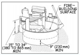
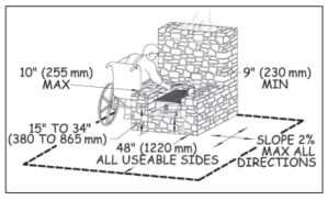
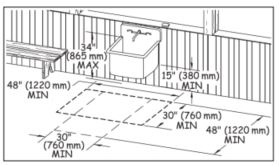
4.2.2 Cooking Surface Height.
The cooking surface shall be at least 15 inches (380 mm) and no more than 34 inches (865 mm) above the floor or ground surface.
4.2.3 Operable Parts.
Operable parts shall comply with the operable parts requirements in ABAAS sections 308 and 309.4.
Exception: Fire rings, grills, fireplaces, and wood stoves shall not be required to comply with ABAAS section 309.4 until models that comply are readily available from more than one source.
4.2.4 Height of Fire-Building Surface.
The fire-building surface within a fire ring shall be at least 9 inches (230 mm) above the floor or ground.
4.2.5 Raised Edge.
Where fire rings, grills, or fireplaces are constructed with raised edges or walls, the depth of the raised edge or wall shall be 10 inches (255 mm) maximum.
4.2.6 Clear Floor or Ground Space.
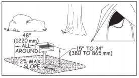
At least 48 inches (1220 mm) by 48 inches (1220 mm) of clear floor or ground space shall be provided on all usable sides of fire rings, grills, fireplaces or woodstoves. This space must be adjacent to the ORAR but may not overlap the ORAR, due to safety considerations.
Exception. The clear floor or ground space at fire rings, grills, fireplaces, or woodstoves may be reduced to no less than 36 inches (915 mm), where a condition for an exception in section 1.1 exists.
4.2.7 Surface.
The surface of the clear floor or ground space shall be firm and stable. The type of surface should be appropriate to the setting and level of development.
4.2.8 Slope.
The slope of the clear floor or ground space required by section 4.2.6 shall not exceed 1:48 (2 percent) in any direction.
Exception. When the surface is not paved or is not elevated above the natural ground, slopes not steeper than 1:33 (3 percent) shall be permitted where necessary for drainage.
4.3.1 General.
Tent platforms are not required. Where provided, tent pads and tent platforms at single camping units shall comply with section 4.3 and shall be connected to an ORAR complying with section 2.0. Where camping units contain more than one tent pad or tent platform, at least 20 percent, but not less than two, of the tent pads or tent platforms shall comply with section 4.3.
4.3.2 Clear Floor or Ground Space.
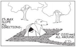
Tent pads and tent platforms shall have clear floor or ground space surrounding the tent that is at least 48 inches (1220 mm) wide. This space shall not overlap the ORAR.
Exception. Where a condition for exception in section 1.1 prohibits full compliance, the clear floor or ground space shall comply with 4.3.2 to the extent practicable.
4.3.3 Slope.
The slope of tent pads and tent platforms shall not exceed 1:48 (2 percent) in any direction.
Exception. When the surface is not paved or is not elevated above the natural ground, slopes not steeper than 1:33 (3 percent) shall be permitted where necessary for drainage.
4.3.4 Tent Pad or Platform Surface.
Tent pads and platforms shall have a surface that is firm and stable and is designed to allow use of tent stakes and other tent securing devices.
Exception. Where a condition for exception in section 1.1 prohibits full compliance, the surface shall comply with 4.3.4 to the extent practicable
4.3.5 Transfer Height.
Tent platform surfaces that are not the same elevation as the ORAR shall be between 17 inches (430 mm) minimum and 19 inches (485 mm) maximum above the floor or ground surface adjacent to the ORAR to facilitate transfer from a wheelchair to the tent platform.
4.4.1 General.
Where benches are provided, each shall comply with section 4.4. At least 20 percent of the benches provided at a recreation site shall be connected to an ORAR complying with section 2.0.
Exception 1. Section 4.3.1 does not apply to built-in benches provided in assembly areas such as amphitheaters. These benches are covered by sections F221.2.1.1, F221.2.2, and 903 of the ABAAS.
Exception 2. In alterations, where a condition for exception in section 1.1 prohibits full compliance with a specific requirement for clear floor or ground space surface, slope, size, or location, the clear floor or ground space shall comply with requirements to the extent practicable.
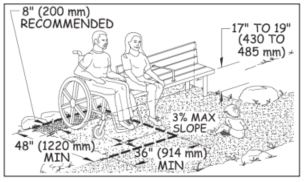
4.4.2 Height.
The front edge of the seat of a bench shall be at least 17 inches (430 mm) and no more than 19 inches (485 mm) above the floor or ground.
4.4.3 Backrest and Armrest.
When more than one bench is provided in the same area, at least 50 percent of the benches shall have a backrest running the full length of the bench. In addition, one armrest shall be provided at one end or in the middle of at least 50 percent of the benches with backrests. The structural strength of backs, armrests, and mounting devices shall comply with section 903.6 of the ABAAS, which states: “Allowable stresses shall not be exceeded for materials used when a vertical or horizontal force of 250 pounds (1112 N) is applied at any point on the seat, fastener, mounting device or supporting structure.”
4.4.4 Clear Floor or Ground Space.
A clear floor or ground space of 36 inches (915 mm) by 48 inches (1220 mm) shall be located at an end the bench with one side of the space adjoining an accessible route, outdoor recreation access route, trail, or beach access route. The long dimension of the clear space shall be roughly perpendicular to the length of the bench.
Locate the clear space to provide shoulder alignment between a person sitting on the bench and a person seated in a wheelchair occupying the clear space. Shoulder alignment generally can be achieved by positioning the back of the bench so it is 8 inches (200 millimeters) closer to the outdoor recreation access route, trail, or beach access route than the back of the required clear floor or ground space adjacent to the end of the bench.
The clear floor or ground space shall not overlap the outdoor recreation access route or trail.
4.4.5 Slope.
The slope of the clear floor or ground space for benches shall not exceed 1:48 (2 percent) in any direction.
Exception. When the surface is not paved or is not elevated above the natural ground, slopes not steeper than 1:33 (3 percent) shall be permitted where necessary for drainage.
4.4.6 Surface.
The surface of the clear floor or ground space for benches shall be firm and stable. The type of surface should be appropriate to the setting and level of development.
4.5.1 General.
Where trash, recycling, and other essential containers are provided, each shall comply with section 4.5.
Exception 1. Fifty percent of the bins in multi-bin containers are exempt from section 4.5.1.
Exception 2. In alterations, where a condition for exception in section 1.1 prohibits full compliance with a specific requirement for clear floor or ground space surface, slope, size, or location, the clear floor or ground space shall comply with requirements to the extent practicable.
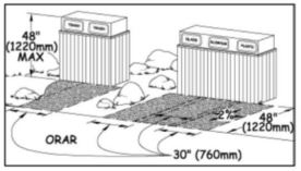
4.5.2 Clear Floor or Ground Space.
A clear floor or ground space shall be provided for each trash, recycling, and other essential container. The space shall be positioned for either forward or side approach to the container opening and be adjacent to or overlap the ORAR.
The clear floor or ground space for a forward approach shall be 36 inches (915 mm) by 48 inches (1220 mm).
The clear floor or ground space for a side approach shall be 30 inches (760 mm) by 60 inches (1525 mm).
4.5.3 Slope.
The slope of the clear floor or ground space for trash, recycling, and other essential containers shall not exceed 1:48 (2 percent) in any direction.
Exception. When the surface is not paved or is not elevated above the natural ground, slopes not steeper than 1:33 (3 percent) shall be permitted where necessary for drainage.
4.5.4 Surface.
The surface of the clear floor or ground space for trash, recycling, and other essential containers shall be firm and stable. The type of surface should be appropriate to the setting and level of development.
4.5.5 Controls and Operating Mechanisms.
Controls and operating mechanisms shall comply with the operable parts requirements in sections 308 and 309.4 of the ABAAS.
Exception. Trash and recycling containers with hinged lids and controls designed to keep out large animals shall not be required to comply with the operable parts requirements in ABAAS section 309.4 until models that comply are readily available from more than one source.
4.5.6 Openings.
Openings in the clear floor or ground space surface shall not allow passage of a sphere more than 1/2 inch (13 mm) diameter. Where possible, elongated openings should be placed perpendicular, or as close to perpendicular as possible, to the dominant direction of travel.
4.6.1 General.
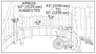
Where telescopes or periscopes are provided, no fewer than two telescopes or periscopes shall be provided at each distinct viewing location in a viewing area. At least one telescope or periscope for each viewing location shall comply with 4.6. The other telescopes shall be usable from a standing position. Telescopes or periscopes at different heights can be mounted separately or on a single pedestal.
Exception. In alterations, where a condition for exception in section 1.1 prohibits full compliance with a specific requirement for clear floor or ground space surface, slope, size, or location, the clear floor or ground space shall comply with requirements to the extent practicable.
4.6.2 Operable Parts.
Controls and operating mechanisms for telescopes and periscopes that are useable from a seated position shall comply with the operable parts requirements in sections 308 and 309.4 of the ABAAS.
4.6.3 Eyepiece.
The eyepiece for the telescope or periscope that is usable from a seated position for viewing each point of interest shall be positioned 43 inches (1090 mm) minimum and 51 inches (1295 mm) maximum above the floor or ground surface.
4.6.4 Clear Floor or Ground Space.
The clear floor or ground space for telescopes and periscopes shall be at least 36 inches (915 mm) by 48 inches (1220 mm) positioned for forward approach to the telescope or periscope, and be located adjacent to an ORAR. Knee and toe clearance complying with ABAAS section 306 shall be provided under the telescope or periscope. Clear floor or ground space shall be positioned so that the eyepiece of the telescope or periscope is centered on the space.
4.6.5 Slope.
The slope of the clear floor or ground space required by section 4.6.4 shall not exceed 1:48 (2 percent) in any direction.
Exception. When the surface is not paved or is not elevated above the natural ground, slopes not steeper than 1:33 (3 percent) shall be permitted where necessary for drainage.
4.6.6 Surface.
The surface of the clear floor or ground space required by section 4.6.4 shall be firm and stable. The type of surface should be appropriate to the setting and level of development.
4.6.7 Openings.
Openings in the clear floor or ground space surface shall not allow passage of a sphere more than 1/2 inch (13 mm) diameter. Where possible, elongated openings should be placed perpendicular, or as close to perpendicular as possible, to the dominant direction of travel.
4.7.1 General.
Electric, water, sewage, and other types of utilities shall comply with section 4.7. All utilities required to be accessible shall be connected to an ORAR complying with section 2.0.
Exception. In alterations, where a condition for exception in section 1.1 prohibits full compliance with a specific requirement for clear floor or ground space surface, slope, size, or location, the clear floor or ground space shall comply with requirements to the extent practicable.
4.7.2 Controls and Operating Mechanisms.
Controls and operating mechanisms shall comply with the operable parts requirements in sections 308 and 309.4 of the ABAAS.
Exception 1. Water hydrants and water utility hookups shall not be required to comply with the operable parts requirements in ABAAS section 309.4 until models that comply are readily available from more than one source.
Exception 2. Sewage hatches shall not be required to comply with the operable parts requirements in ABAAS sections 308 and 309.4.
4.7.3 Slope.
The slope of the clear floor or ground spaces required by section 4.0 shall not exceed 1:48 (2 percent) in any direction.
Exception. When the surface is not paved or is not elevated above the natural ground, slopes not steeper than 1:33 (3 percent) shall be permitted where necessary for drainage.
4.7.4 Surface.
The surface of the clear floor or ground spaces required by section 4.0 shall be firm and stable. The type of surface should be appropriate to the setting and level of development.
4.7.5 Openings.
Openings in surface of the clear floor or ground spaces required by section 2.0 shall not allow passage of a sphere more than 1/2 inch (13 mm) in diameter. Where possible, elongated openings should be placed perpendicular, or as close to perpendicular as possible, to the dominant direction of travel.
4.7.6 Water Hydrant Clear Floor or Ground Space.
Clear floor or ground space around a water hydrant shall be 48 inches (1220 mm) by 72 inches (1830 mm) with the long side of the space adjoining an outdoor recreation access route, trail, beach access route, or another clear ground space. The clear space at the water hydrant shall not overlap the outdoor recreation access route, trail or beach access route leading to or passing that water hydrant.
4.7.7 Water Spouts.
Water spouts shall be located in the space so that the water spout is 11 inches (280 mm) minimum and 12 inches (305 mm) maximum from the rear center of the long side of the clear floor or ground space. Water spouts must be 28 inches (710 mm) minimum and 36 inches (915 mm) maximum above the ground or floor.
4.7.8 Utility and Dump Station Hookup Clear Floor or Ground Space.
The clear floor or ground space around utility and dump station hookups shall be at least 30 inches (760 mm) by 60 inches (1525 mm). The clear space shall be located with the long side of the space adjoining or overlapping an accessible parking space or accessible pull-up space for recreational vehicles, or an ORAR connecting the accessible vehicle pull-up space to the hookups. Hookups shall be located at the rear center of the space. Clear spaces of adjacent utility hookups may overlap. Bollards or other barriers shall not obstruct the clear floor or ground space in front of the hook-ups.
Where utility sinks are provided in a recreation facility that also contains a cook top or conventional range, at least 5 percent, but not less than one in each accessible space, shall comply with section 4.7.9 and shall be connected to an ORAR complying with section 2.0.
4.7.9.2 Clear Floor or Ground Space.
Clear floor or ground space 48 inches (1220 mm) by 30 inches (760 mm) oriented for a forward or parallel approach shall be provided for utility sinks required to meet 4.7.9. This space shall not overlap the ORAR.
The counter or rim of the sink shall be no more than 34 inches (865 mm) above the floor or ground. Water spouts must be 28 inches (710 mm) minimum and 36 inches (915 mm) maximum above the ground or floor.
The bottom of the bowl shall be at least 15 inches (380 mm) above the floor or ground.
4.8.1 General.
Outdoor rinsing showers shall provide a hand-held shower spray unit complying with ABAAS section 608.6.
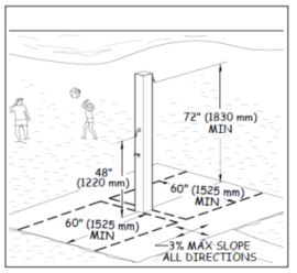
Exception: In facilities where vandalism is a consideration, two fixed shower heads may be provided instead of the hand-held shower spray. One fixed showerhead shall be 48 inches (1220 mm) above the floor or ground surface, and one fixed shower head shall be 72 inches (1830 mm) minimum above the floor or ground surface.
4.8.2 Clear Floor or Ground Space.
The clear floor or ground space around outdoor rinsing showers shall be 60 inches (1525 mm) by 60 inches (1525 mm). The space shall be centered on the showerhead and located so that the showerhead is at the rear of the space.
5.1.1. General.
Camp shelters at single camping units shall comply with 5.1. Where camping units contain more than one camp shelter, at least 20 percent, but not less than two, of the camp shelters shall comply with section 5.1. Camp shelters located on trails shall be connected to other constructed features in the unit by a trail complying with the FSTAG. Camp shelters located in a campground, not on a trail, shall be connected to other constructed features by an ORAR complying with section 2.0.
5.1.2 Level or Sloped Entry.
Camp shelters providing roll-in access shall have a level or sloped entry that complies with the FSORAG Outdoor Recreation Access Route technical provisions if the camp shelter is in a campground with a development level of 3 or higher. If the camp shelter is accessed from a trail, the sloped entry must comply with the FSTAG Trail provisions.
5.1.3 Slope.
The slope of the surface of the clear floor or ground space inside the camp shelter shall not be steeper than 1:48 (2 percent) in all directions.
5.1.4 Turning Space.
Where the camp shelter floor is not elevated above the trail or ORAR, a turning space complying with ABAAS section 304.3 shall be provided.
5.1.5 Floor Height.
Where the floor at the entrance to the camp shelter is elevated above the ground surface, the floor shall be 17 (430 mm) high minimum to 19 inches (485 mm) high maximum measured from the clear ground space to the floor surface inside the camp shelter.
5.1.6 Clear Floor or Ground Space.
A clear floor or ground space at least 36 inches (915 mm) by 48 inches (1220 mm) shall be provided parallel to the entrance to the camp shelter. One full unobstructed side of the clear ground space shall adjoin or overlap the trail or ORAR, as applicable, or another clear ground space.
5.1.7 Surface.
The surface of the clear ground space shall be firm and stable.
5.1.8 Slope.
The slope of the surface of the clear ground space shall not be steeper than 1:48 (2 percent) in any direction.
Exception: When the surface is not paved or is not elevated above the natural ground, slopes not steeper than 1:33 (3 percent) shall be permitted where necessary for drainage.
5.1.9 Doors.
Where provided, doors shall comply with ABAAS section 404. The door shall not swing into or otherwise obstruct the clear floor or ground space or the turning space required by 5.1.4.
5.2.1 General.
All toilet buildings with one riser at recreation sites with a FS Recreation Site Development Scale of 3 or higher shall comply with sections 603, 604.4, 604.5, 604.6, and 604.7 of the ABAAS. All toilet buildings at recreation sites with a FS Recreation Site Development Scale level of 3 or higher with multiple risers shall comply with section 604 of the ABAAS, and shall also comply with other applicable sections of the ABAAS if other amenities are provided within the building.
5.3.1 General.
Pit toilets may only be provided in FS recreation sites with a Recreation Site Development Scale level of 2 or less or at remote cabin locations. All pit toilets shall comply with section 5.3 and be connected to an ORAR complying with section 2.0. Where pit toilets are constructed in sites that are not accessed by motor vehicles, the pit toilet and all constructed features in the site shall be connected by trail segments complying with the FSTAG.
5.3.2 Turning Space and Clear Floor or Ground Space.
Turning space and clear floor or ground space complying with 5.3 shall be provided at pit toilets.
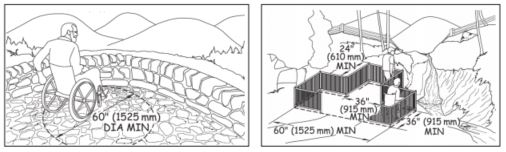
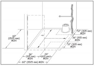
The clear floor or ground space shall be 60 inches (1525 mm) wide minimum measured parallel with the back of the pit toilet, and 56 inches (1420 mm) deep minimum measured parallel to the sides of the pit toilet. The turning space shall be at least 60 inches (1,525 millimeters) in diameter or T-shaped with a minimum 60- by 36-inch (1,525 by 915 millimeter) arm and a minimum 36-inch (915 millimeter) - wide by 24-inch (610 millimeter) -long base. The turning space and clear floor or ground space may overlap.
The surface of the turning space and clear floor or ground space shall be firm and stable.
The slope of the turning space and clear floor or ground space surface shall not be steeper than 1:48 (2 percent) in all directions.
Exception: When the surface is not paved or is not elevated above the natural ground, slopes not steeper than 1:33 (3 percent) shall be permitted where necessary for drainage
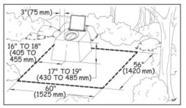
The total height of the toilet seat on the riser for a pit toilet shall be between 17 inches (430 mm) and 19 inches (485 mm) above the floor or ground surface.
5.3.3.2 Location Where Walls Provided.
Where walls or partitions are provided, the seat shall be positioned with a wall or partition to the rear and to one side of the seat for a left-hand or right-hand approach. The back of the riser shall be flush against the back wall. The centerline of the seat shall be 16 inches (405 mm) minimum to 18 inches (455 mm) maximum from the side wall or partition.
5.3.3.3 Location Where Walls Not Provided.
Where walls or partitions are not provided, the seat shall be positioned in a corner of the clear floor or ground space required by 5.3.2 for a left-hand or right-hand approach. The back of the seat shall be flush against the perimeter of the clear floor or ground space.
5.3.4 Grab Bars.
Where walls or partitions are provided, grab bars complying with ABAAS section 604.5 shall be provided.
Exception: Where the walls or partitions cannot support the force specified in ABAAS section 609.8, grab bars shall not be installed. In such cases, the riser shall have vertical or nearly vertical sides and a flat area on each side of the seat that is about 3 inches (75 millimeters) wide.
5.3.5 Doors.
Where provided, doors shall comply with ABAAS section 404. The door shall not swing into or otherwise obstruct the clear floor or ground space required by 5.3.2.1.
5.3.6 Entrance.
The entrance to the toilet shall be level with the surrounding surface.
Exception: Where bedrock, perma-frost or other environmental conditions prohibit a level entry or the toilet design (such as a composting toilet) necessitates a raised toilet structure, a sloped entry complying with the FSTAG provisions for a trail may connect the toilet entrance with the trail or ORAR. A 60 inch by 60 inch (1,220 millimeters by 1,220 millimeters) level landing must be provided outside the door to the toilet. Sloped entries do not require handrails.
6.1 General.
Beach access routes complying with 6.0 shall be provided at developed beach sites as required by 6.0. Beach access routes shall be permanent or removable surfaces. Removable beach access routes can be moved to a protected storage area during storms and other periods when the routes are subject to damage.
Exception 1. Where a condition in 1.1 prohibits full compliance with a specific requirement in 6.0 on a portion of a beach access route, that portion of the beach access route shall comply with the specific requirement to the extent practicable. The basis for the determination shall be documented and maintained with the records of the construction or alteration project.
Exception 2. If it is determined not to be practicable to provide a beach access route complying with 6.0 after applying Exception 1, a beach access route shall not be required. The basis for the determination of impracticability shall be documented, the documentation shall be maintained with the records of the construction or alteration project, and notification of this determination shall be sent to the Access Board. A form is available on the Access Board’s Website http://www.access-board.gov/guidelinesand-standards/recreation-facilities/outdoor-developed-areas for optional use.
Exception 3. Removable beach access routes shall not be required to comply with the grade requirements in section 6.7 and the resting interval requirement in section 6.8.
Exception 4. Beach access routes shall not be required where pedestrian access to the beach is not permitted.
6.2 Where Required.
Beach access routes shall be provided in a number complying with 6.3 where any of the following facilities to serve the beach are constructed or altered:
6.2.1 Circulation Routes Constructed at Beaches.
Beach access routes shall be provided where circulation routes such as boardwalks, walkways, or dune crossings are constructed along or across developed beach sites to provide pedestrian access to the beach or shoreline.
6.2.2 Parking Facilities Constructed at Beaches.
Where parking facilities are constructed at developed beach sites and pedestrian access to the beach is provided near the parking facilities, beach access routes shall be provided.
6.2.3 Bathing and Toilet Facilities Constructed at Beaches.
Where bathing and toilet facilities are constructed at developed beach sites and pedestrian access points to the beach are provided near the bathing and toilet facilities, beach access routes shall be provided.
6.2.4 Beach Nourishment.
Beach access routes shall be provided where a beach nourishment project is undertaken.
Exception: No more than 20 percent of the costs of a facility construction or alteration project or beach nourishment project shall be required to be expended to provide beach access routes.
6.3 Minimum Number.
At least one beach access route shall be provided for each 1/2 mile of shoreline where required by 6.2.
Exception: The number of beach access routes shall not be required to exceed the number of pedestrian access points that are provided to a beach.
6.4 Connections.
Beach access routes shall coincide with or be located in the same general area as the pedestrian access points to the beach. Beach access routes shall extend to the:
6.4.1.
High tide level at tidal beaches;
6.4.2.
Mean high water level at river beaches; and

6.5 Surface.
The surface of beach access routes and their related resting intervals shall be firm and stable.
6.6 Clear Width.
The clear width of beach access routes shall be 60 inches (1525 mm) minimum.
Exception: At dune crossings, the clear width of beach access routes that are not removable shall be permitted to be reduced to 48 inches (1220 mm) minimum.
6.7.1 Running Slope (Grade).
The running slope (grade) of a Beach Access Route shall comply with all applicable provisions of this section.
| Running Slope (Grade) and Resting Intervals on Beach Access Routes | Maximum Length of Segment | |
| Steeper than | But not Steeper than | |
| 1:20 (5 percent) | 1:12 (8.33 percent) | 50 feet (15 m) |
| 1:12 (8.33 percent) | 1:10 (10 percent) | 30 feet (9 m) |
Exception. Elevated dune crossings shall not be required to comply with the resting interval requirements in 6.7.1.
The grade of a Beach Access Route shall be 1:20 (5 percent) or less for any distance.
A grade of up to 1:12 (8.33 percent) is permitted for up to 50 feet (15 m) of a beach access route. Resting intervals complying with section 2.3 shall be provided at distances of no more than 50 feet (15 m) apart.
A grade of up to 1:10 (10 percent) is permitted for up to 30 feet (9 m) of a beach access route. Resting intervals complying with section 2.3 shall be provided at distances of no more than 30 feet (9 m) apart.
6.7.2 Cross Slope.
The cross slope of a beach access route shall be no more than 1:33 (3 percent). Where the surface is paved or is elevated above the natural ground, the cross slope shall not be steeper than 1:48 (2 percent).
6.8.1 Size.
The resting interval length shall be a minimum of 60 inches (1525 mm) long by 60 inches (1525 mm) wide.
6.8.2 Grade and cross slope.
The slope of a resting interval shall not be steeper than 1:33 (3 percent) in any direction. Where the surface is paved or is elevated above the natural ground, the surface shall not be steeper than 1:48 (2 percent) in any direction.
6.9 Tread Obstacles.
Obstacles on beach access routes and their related resting intervals shall not exceed 1 inch (25 mm) in height measured vertically to the highest point. Where the surface is paved or is elevated above the natural ground, obstacles shall not exceed 1/2 inch (13 mm) in height measured vertically to the highest point. Where possible, obstacles should not be closer than 48 inches (1220 mm) apart.
6.10 Openings.
Openings in the surface of beach access routes and their related resting intervals may be up to 1/2 inch (13 millimeters) wide. Where possible, elongated openings should be placed perpendicular, or as close to perpendicular as possible, to the dominant direction of travel.
6.11 Protruding Objects.
Constructed features, including signs, shall not extend into the space above a beach access route more than 4 inches (100 mm) if they are between 27 inches (685 mm) and 80 inches (2030 mm) above the surface of the beach access route.
6.11.1 Natural Elements.
Accessibility guidelines for protruding objects do not apply to natural elements such as tree branches and rock formations. However, safety regulations or Forest Service construction and maintenance standards may define clear space and limit the allowable extension of natural protruding objects over the beach access route surface.
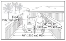
6.12 Handrails and Edge Protection.
Where elevated dune crossings or dune crossings steeper than 1:20 (5 percent) are part of beach access routes, handrails complying with ABAAS section 505 and edge protection complying with ABAAS section 405.9 shall be provided.
6.13 Outdoor Constructed Features.
Where provided on circulation paths or beach access routes at beaches, outdoor constructed features such as picnic tables, grills or water hydrants, shall comply with technical provisions for that constructed feature as detailed in these Forest Service Outdoor Recreation Accessibility Guidelines.
6.14 Gates and Barriers.
Where gates or barriers are constructed to control access to beach access routes, gates and barriers shall comply with 6.14.
6.14.1 Clear Width.
Gate openings and openings in barriers for pedestrian passage shall provide a clear width of 36 inches (915 mm), complying with ODAAG, section 1017.3 Clear Tread Width.
6.14.2 Gate Hardware.
Gate hardware shall comply with operable controls requirements in ABAAS section 309.4 and 404.2.7.
APPENDIX A: Provisions of the Architectural Barriers Act Accessibility Standards (ABAAS)
That Are Referenced in the FSORAG Technical Provisions
The ABAAS are available at http://www.access-board.gov/guidelines-andstandards/buildings-and-sites/about-the-aba-standards/aba-standards.
F208.1 General.
Where parking spaces are provided, parking spaces shall be provided in accordance with F208.
EXCEPTION: Parking spaces used exclusively for buses, trucks, other delivery vehicles, law enforcement vehicles, or vehicular impound shall not be required to comply with F208 provided that lots accessed by the public are provided with a passenger loading zone complying with 503.
F208.2 Minimum Number.
Parking spaces complying with 502 shall be provided in accordance with Table F208.2 except as required by F208.2.1, F208.2.2, and F208.2.3. Where more than one parking facility is provided on a site, the number of accessible spaces provided on the site shall be calculated according to the number of spaces required for each parking facility.
| Total Number of Parking Spaces Provided in Parking Facility | Minimum Number of Required accessible Parking Spaces |
| 1 to 25 | 1 |
| 26 to 50 | 2 |
| 51 to 75 | 3 |
| 76 to 100 | 4 |
| 101 to 150 | 5 |
| 151 to 200 | 6 |
| 201 to 300 | 7 |
| 301 to 400 | 8 |
| 401 to 500 | 9 |
| 501 to 1000 | 2 percent of total |
| 1001 and over | 20, plus 1 for each 100, or fraction thereof, over 1000 |
F208.2.4 Van Parking Spaces.
For every six or fraction of six parking spaces required by F208.2 to comply with 502, at least one shall be a van parking space complying with 502.
F208.3 Location.
Parking facilities shall comply with F208.3
F208.3.1 General.
Parking spaces complying with 502 that serve a particular building or facility shall be located on the shortest accessible route from parking to an entrance complying with F206.4. Where parking serves more than one accessible entrance, parking spaces complying with 502 shall be dispersed and located on the shortest accessible route to the accessible entrances. In parking facilities that do not serve a particular building or facility, parking spaces complying with 502 shall be located on the shortest accessible route to an accessible pedestrian entrance of the parking facility.
304.1 General.
Turning space shall comply with 304.
304.3.1 Circular Space.
The turning space shall be a space of 60 inches (1525 mm) diameter minimum. The space shall be permitted to include knee and toe clearance complying with 306.
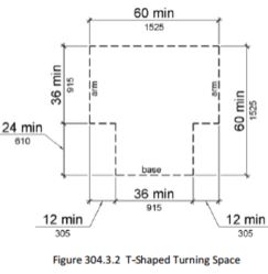
304.3.2 T-Shaped Space.
The turning space shall be a T-shaped space within a 60 inch (1525 mm) square minimum with arms and base 36 inches (915 mm) wide minimum. Each arm of the T shall be clear of obstructions 12 inches (305 mm) minimum in each direction and the base shall be clear of obstructions 24 inches (610 mm) minimum. The space shall be permitted to include knee and toe clearance complying with 306 only at the end of either the base or one arm.
305.1 General.
Clear floor or ground space shall comply with 305.
305.2 Floor or Ground Surfaces.
Floor or ground surfaces of a clear floor or ground space shall comply with 302. Changes in level are not permitted.
EXCEPTION: Slopes not steeper than 1:48 shall be permitted.
305.3 Size.
The clear floor or ground space shall be 30 inches (760 mm) minimum by 48 inches (1220 mm) minimum.
305.4 Knee and Toe Clearance.
Unless otherwise specified, clear floor or ground space shall be permitted to include knee and toe clearance complying with 306.
305.5 Position.
Unless otherwise specified, clear floor or ground space shall be positioned for either forward or parallel approach to an element.
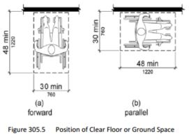
305.6 Approach.
One full unobstructed side of the clear floor or ground space shall adjoin an accessible route or adjoin another clear floor or ground space.
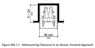
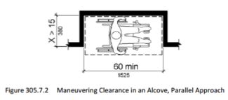
305.7 Maneuvering Clearance.
Where a clear floor or ground space is located in an alcove or otherwise confined on all or part of three sides, additional maneuvering clearance shall be provided in accordance with 305.7.1 and 305.7.2.
305.7.1 Forward Approach.
Alcoves shall be 36 inches (915 mm)wide minimum where the depth exceeds 24 inches (610 mm).
305.7.2 Parallel Approach.
Alcoves shall be 60 inches (1525 mm) wide minimum where the depth exceeds 15 inches (380 mm).
306.1 General.
Where space beneath an element is included as part of clear floor or ground space or turning space, the space shall comply with 306. Additional space shall not be prohibited beneath an element but shall not be considered as part of the clear floor or ground space or turning space.
306.2.1 General.
Space under an element between the finish floor or ground and 9 inches (230 mm) above the finish floor or ground shall be considered toe clearance and shall comply with 306.2.
306.2.2 Maximum Depth.
Toe clearance shall extend 25 inches (635 mm) maximum under an element.
306.2.3 Minimum Required Depth.
Where toe clearance is required at an element as part of a clear floor space, the toe clearance shall extend 17 inches (430 mm) minimum under the element.
306.2.4 Additional Clearance.
Space extending greater than 6 inches (150 mm) beyond the available knee clearance at 9 inches (230 mm) above the finish floor or ground shall not be considered toe clearance.
306.3.1 General.
Space under an element between 9 inches (230 mm) and 27 inches (685 mm) above the finish floor or ground shall be considered knee clearance and shall comply with 306.3.
306.3.2 Maximum Depth.
Knee clearance shall extend 25 inches (635 mm) maximum under an element at 9 inches (230 mm) above the finish floor or ground.
306.3.3 Minimum Required Depth.
Where knee clearance is required under an element as part of a clear floor space, the knee clearance shall be 11 inches (280 mm) deep minimum at 9 inches (230 mm) above the finish floor or ground, and 8 inches (205 mm) deep minimum at 27 inches (685 mm) above the finish floor or ground.
306.3.4 Clearance Reduction.
Between 9 inches (230 mm) and 27 inches (685 mm) above the finish floor or ground, the knee clearance shall be permitted to reduce at a rate of 1 inch (25 mm) in depth for each 6 inches (150 mm) in height.
308.1 General.
Reach ranges shall comply with 308.
308.2.1 Unobstructed.
Where a forward reach is unobstructed, the high forward reach shall be 48 inches (1220 mm) maximum and the low forward reach shall be 15 inches (380 mm) minimum above the finish floor or ground.
308.2.2 Obstructed High Reach.
Where a high forward reach is over an obstruction, the clear floor space shall extend beneath the element for a distance not less than the required reach depth over the obstruction. The high forward reach shall be 48 inches (1220 mm) maximum where the reach depth is 20 inches (510 mm) maximum. Where the reach depth exceeds 20 inches (510 mm), the high forward reach shall be 44 inches (1120 mm) maximum and the reach depth shall be 25 inches (635 mm) maximum.
308.3.1 Unobstructed.
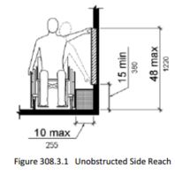
Where a clear floor or ground space allows a parallel approach to an element and the side reach is unobstructed, the high side reach shall be 48 inches (1220 mm) maximum and the low side reach shall be 15 inches (380 mm) minimum above the finish floor or ground.
EXCEPTIONS: 1. An obstruction shall be permitted between the clear floor or ground space and the element where the depth of the obstruction is 10 inches (255 mm) maximum. 2. Operable parts of fuel dispensers shall be permitted to be 54 inches (1370 mm) maximum measured from the surface of the vehicular way where fuel dispensers are installed on existing curbs.
308.3.2 Obstructed High Reach.
Where a clear floor or ground space allows a parallel approach to an element and the high side reach is over an obstruction, the height of the obstruction shall be 34 inches (865 mm) maximum and the depth of the obstruction shall be 24 inches (610 mm) maximum. The high side reach shall be 48 inches (1220 mm) maximum for a reach depth of 10 inches (255 mm) maximum. Where the reach depth exceeds 10 inches (255 mm), the high side reach shall be 46 inches (1170 mm) maximum for a reach depth of 24 inches (610 mm) maximum.
EXCEPTIONS: 1. The top of washing machines and clothes dryers shall be permitted to be 36 inches (915 mm) maximum above the finish floor.
2. Operable parts of fuel dispensers shall be permitted to be 54 inches (1370 mm) maximum measured from the surface of the vehicular way where fuel dispensers are installed on existing curbs.
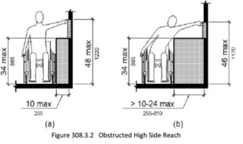
309.1 General.
Operable parts shall comply with 309.
309.2 Clear Floor Space.
A clear floor or ground space complying with 305 shall be provided.
309.3 Height.
Operable parts shall be placed within one or more of the reach ranges specified in 308.
309.4 Operation.
Operable parts shall be operable with one hand and shall not require tight grasping, pinching, or twisting of the wrist. The force required to activate operable parts shall be 5 pounds (22.2 N) maximum.
EXCEPTION: Gas pump nozzles shall not be required to provide operable parts that have an activating force of 5 pounds (22.2 N) maximum.
404.2.3 Doorways - Clear Width.
Door openings shall provide a clear width of 32 inches (815 mm) minimum. Clear openings of doorways with swinging doors shall be measured between the face of the door and the stop, with the door open 90 degrees. Openings more than 24 inches (610 mm) deep shall provide a clear opening of 36 inches (915 mm) minimum. There shall be no projections into the required clear opening width lower than 34 inches (865 mm) above the finish floor or ground. Projections into the clear opening width between 34 inches (865 mm) and 80 inches (2030 mm) above the finish floor or ground shall not exceed 4 inches (100 mm).
EXCEPTIONS: 1. In alterations, a projection of 5/8 inch (16 mm) maximum into the required clear width shall be permitted for the latch side stop.
2. Door closers and door stops shall be permitted to be 78 inches (1980 mm) minimum above the finish floor or ground.
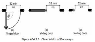
404.2.7 Door and Gate Hardware.
Handles, pulls, latches, locks, and other operable parts on doors and gates shall comply with 309.4. Operable parts of such hardware shall be 34 inches (865 mm) minimum and 48 inches (1220 mm) maximum above the finish floor or ground. Where sliding doors are in the fully open position, operating hardware shall be exposed and usable from both sides.
405.9 Edge Protection.
Edge protection complying with 405.9.1 or 405.9.2 shall be provided on each side of ramp runs and at each side of ramp landings.
EXCEPTIONS: 1. Edge protection shall not be required on ramps that are not required to have handrails and have sides complying with 406.3.
2. Edge protection shall not be required on the sides of ramp landings serving an adjoining ramp run or stairway.
3. Edge protection shall not be required on the sides of ramp landings having a vertical drop-off of 1/2 inch (13 mm) maximum within 10 inches (255 mm) horizontally of the minimum landing area specified in 405.7.
405.9.1 Extended Floor or Ground Surface.
The floor or ground surface of the ramp run or landing shall extend 12 inches (305 mm) minimum beyond the inside face of a handrail complying with 505.
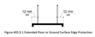
405.9.2 Curb or Barrier.
A curb or barrier shall be provided that prevents the passage of a 4 inch (100 mm) diameter sphere, where any portion of the sphere is within 4 inches (100 mm) of the finish floor or ground surface.
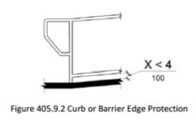
405.10 Wet Conditions.
Landings subject to wet conditions shall be designed to prevent the accumulation of water.
502.1 General.
Car and van parking spaces shall comply with 502. Where parking spaces are marked with lines, width measurements of parking spaces and access aisles shall be made from the centerline of the markings.
EXCEPTION: Where parking spaces or access aisles are not adjacent to another parking space or access aisle, measurements shall be permitted to include the full width of the line defining the parking space or access aisle.
502.2 Vehicle Spaces.
Car parking spaces shall be 96 inches (2440 mm) wide minimum and van parking spaces shall be 132 inches (3350 mm) wide minimum, shall be marked to define the width, and shall have an adjacent access aisle complying with 502.3.
EXCEPTION: Van parking spaces shall be permitted to be 96 inches (2440 mm) wide minimum where the access aisle is 96 inches (2440 mm) wide minimum.
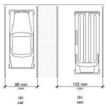
502.3 Access Aisle.
Access aisles serving parking spaces shall comply with 502.3. Access aisles shall adjoin an accessible route. Two parking spaces shall be permitted to share a common access aisle.
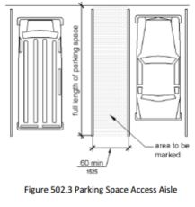
502.3.1 Width.
Access aisles serving car and van parking spaces shall be 60 inches (1525 mm) wide minimum.
502.3.2 Length.
Access aisles shall extend the full length of the parking spaces they serve.
502.3.3 Marking.
Access aisles shall be marked so as to discourage parking in them.
502.3.4 Location.
Access aisles shall not overlap the vehicular way. Access aisles shall be permitted to be placed on either side of the parking space except for angled van parking spaces which shall have access aisles located on the passenger side of the parking spaces.
502.4 Floor or Ground Surfaces.
Parking spaces and access aisles serving them shall comply with 302. Access aisles shall be at the same level as the parking spaces they serve. Changes in level are not permitted.
EXCEPTION: Slopes not steeper than 1:48 shall be permitted.
502.6 Identification.
Parking space identification signs shall include the International Symbol of Accessibility complying with 703.7.2.1. Signs identifying van parking spaces shall contain the designation "van accessible." Signs shall be 60 inches (1525 mm) minimum above the finish floor or ground surface measured to the bottom of the sign.
502.7 Relationship to Accessible Routes.
Parking spaces and access aisles shall be designed so that cars and vans, when parked, cannot obstruct the required clear width of adjacent accessible routes.
505.1 General.
Handrails provided along walking surfaces complying with 403, required at ramps complying with 405, and required at stairs complying with 504 shall comply with 505.
505.2 Where Required.
Handrails shall be provided on both sides of stairs and ramps.
EXCEPTION: In assembly areas, handrails shall not be required on both sides of aisle ramps where a handrail is provided at either side or within the aisle width.
505.3 Continuity.
Handrails shall be continuous within the full length of each stair flight or ramp run. Inside handrails on switchback or dogleg stairs and ramps shall be continuous between flights or runs.
EXCEPTION: In assembly areas, handrails on ramps shall not be required to be continuous in aisles serving seating.
505.4 Height.
Top of gripping surfaces of handrails shall be 34 inches (865 mm) minimum and 38 inches (965 mm) maximum vertically above walking surfaces, stair nosings, and ramp surfaces. Handrails shall be at a consistent height above walking surfaces, stair nosings, and ramp surfaces.
Figure 505.4 Handrail Height
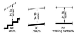
505.5 Clearance.
Clearance between handrail gripping surfaces and adjacent surfaces shall be 1 1/2 inches (38 mm) minimum.

505.6 Gripping Surface.
Handrail gripping surfaces shall be continuous along their length and shall not be obstructed along their tops or sides. The bottoms of handrail gripping surfaces shall not be obstructed for more than 20 percent of their length. Where provided, horizontal projections shall occur 1 1/2 inches (38 mm) minimum below the bottom of the handrail gripping surface.
EXCEPTIONS: 1. Where handrails are provided along walking surfaces with slopes not steeper than 1:20, the bottoms of handrail gripping surfaces shall be permitted to be obstructed along their entire length where they are integral to crash rails or bumper guards.
2. The distance between horizontal projections and the bottom of the gripping surface shall be permitted to be reduced by 1/8 inch (3.2 mm) for each 1/2 inch (13 mm) of additional handrail perimeter dimension that exceeds 4 inches (100 mm).
505.7 Cross Section.
Handrail gripping surfaces shall have a cross section complying with 505.7.1 or 505.7.2.
505.7.1 Circular Cross Section.
Handrail gripping surfaces with a circular cross section shall have an outside diameter of 1 1/4 inches (32 mm) minimum and 2 inches (51 mm) maximum.
505.7.2 Non-Circular Cross Sections.
Handrail gripping surfaces with a non-circular cross section shall have a perimeter dimension of 4 inches (100 mm) minimum and 6 1/4 inches (160 mm) maximum, and a cross-section dimension of 2 1/4 inches (57 mm) maximum.
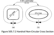
505.8 Surfaces.
Handrail gripping surfaces and any surfaces adjacent to them shall be free of sharp or abrasive elements and shall have rounded edges.
505.9 Fittings.
Handrails shall not rotate within their fittings.
505.10 Handrail Extensions.
Handrail gripping surfaces shall extend beyond and in the same direction of stair flights and ramp runs in accordance with 505.10.
EXCEPTIONS: 1. Extensions shall not be required for continuous handrails at the inside turn of switchback or dogleg stairs and ramps.
2. In assembly areas, extensions shall not be required for ramp handrails in aisles serving seating where the handrails are discontinuous to provide access to seating and to permit crossovers within aisles.
3. In alterations, full extensions of handrails shall not be required where such extensions would be hazardous due to plan configuration.
505.10.1 Top and Bottom Extension at Ramps.
Ramp handrails shall extend horizontally above the landing for 12 inches (305 mm) minimum beyond the top and bottom of ramp runs. Extensions shall return to a wall, guard, or the landing surface, or shall be continuous to the handrail of an adjacent ramp run.
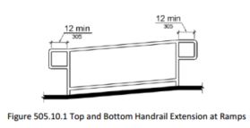
505.10.2 Top Extension at Stairs.
At the top of a stair flight, handrails shall extend horizontally above the landing for 12 inches (305 mm) minimum beginning directly above the first riser nosing. Extensions shall return to a wall, guard, or the landing surface, or shall be continuous to the handrail of an adjacent stair flight.
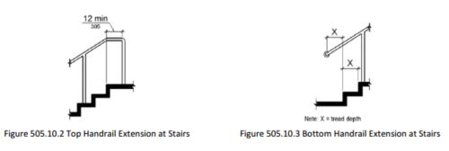
505.10.3 Bottom Extension at Stairs.
At the bottom of a stair flight, handrails shall extend at the slope of the stair flight for a horizontal distance at least equal to one tread depth beyond the last riser nosing. Extension shall return to a wall, guard, or the landing surface, or shall be continuous to the handrail of an adjacent stair flight.
603 Toilet and Bathing Rooms
(This section is to be used for toilet buildings with a single riser such as SSTs, but not for pit toilets. See definition of pit toilet in Technical Provisions section of FSORAG.)
603.1 General.
Toilet and bathing rooms shall comply with 603.
603.2 Clearances.
Clearances shall comply with 603.2.
603.2.1 Turning Space.
Turning space complying with 304 shall be provided within the room.
603.2.2 Overlap.
Required clear floor spaces, clearance at fixtures, and turning space shall be permitted to overlap.
603.2.3 Door Swing.
Doors shall not swing into the clear floor space or clearance required for any fixture. Doors shall be permitted to swing into the required turning space.
EXCEPTIONS: 1. Doors to a toilet room or bathing room for a single occupant accessed only through a private office and not for common use or public use shall be permitted to swing into the clear floor space or clearance provided the swing of the door can be reversed to comply with 603.2.3.
2. Where the toilet room or bathing room is for individual use and a clear floor space complying with 305.3 is provided within the room beyond the arc of the door swing, doors shall be permitted to swing into the clear floor space or clearance required for any fixture.
603.3 Mirrors.
Mirrors located above lavatories or countertops shall be installed with the bottom edge of the reflecting surface 40 inches (1015 mm) maximum above the finish floor or ground. Mirrors not located above lavatories or countertops shall be installed with the bottom edge of the reflecting surface 35 inches (890 mm) maximum above the finish floor or ground.
Advisory 603.3 Mirrors. A single full-length mirror can accommodate a greater number of people, including children. In order for mirrors to be usable by people who are ambulatory and people and people who use wheelchairs, the top edge of mirrors should be 74 inches (1880 mm) minimum from the floor or ground
603.4 Coat Hooks and Shelves.
Coat hooks shall be located within one of the reach ranges specified in 308. Shelves shall be located 40 inches (1015 mm) minimum and 48 inches (1220 mm) maximum above the finish floor.
604 Water Closets and Toilet Compartments
(This section is to be used for toilet buildings with multiple risers provided at recreation sites with a FS Recreation Site Development Scale of 3 or higher, and for the Exception under Pit Toilets in General Forest Areas FSORAG 6.6).
604.1 General.
Water closets and toilet compartments shall comply with 604.2 through 604.8.
EXCEPTION: Water closets and toilet compartments for children's use shall be permitted to comply with 604.9.
604.2 Location.
The water closet shall be positioned with a wall or partition to the rear and to one side. The centerline of the water closet shall be 16 inches (405 mm) minimum to 18 inches (455 mm) maximum from the side wall or partition, except that the water closet shall be 17 inches (430 mm) minimum and 19 inches (485 mm) maximum from the side wall or partition in the ambulatory accessible toilet compartment specified in 604.8.2. Water closets shall be arranged for a left-hand or right-hand approach.
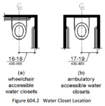
604.3 Clearance.
Clearances around water closets and in toilet compartments shall comply with 604.3.
604.3.1 Size.
Clearance around a water closet shall be 60 inches (1525 mm) minimum measured perpendicular from the side wall and 56 inches (1420 mm) minimum measured perpendicular from the rear wall.
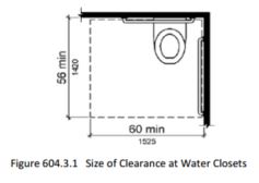
604.3.2 Overlap.
The required clearance around the water closet shall be permitted to overlap the water closet, associated grab bars, dispensers, sanitary napkin disposal units, coat hooks, shelves, accessible routes, clear floor space and clearances required at other fixtures, and the turning space. No other fixtures or obstructions shall be located within the required water closet clearance.
EXCEPTION: In residential dwelling units, a lavatory complying with 606 shall be permitted on the rear wall 18 inches (455 mm) minimum from the water closet centerline where the clearance at the water closet is 66 inches (1675 mm) minimum measured perpendicular from the rear wall.
604.4 Seats.
The seat height of a water closet above the finish floor shall be 17 inches (430 mm) minimum and 19 inches (485 mm) maximum measured to the top of the seat. Seats shall not be sprung to return to a lifted position.
EXCEPTIONS: 1. A water closet in a toilet room for a single occupant accessed only through a private office and not for common use or public use shall not be required to comply with 604.4. 2. In residential dwelling units, the height of water closets shall be permitted to be 15 inches (380 mm) minimum and 19 inches (485 mm) maximum above the finish floor measured to the top of the seat.
604.5 Grab Bars.
Grab bars for water closets shall comply with 609. Grab bars shall be provided on the side wall closest to the water closet and on the rear wall.
Advisory 604.5 Grab Bars Exception 2. Reinforcement must be sufficient to permit the installation of rear and side wall grab bars that fully meet all accessibility requirements including, but not limited to, required length, installation height, and structural strength.
604.5.1 Side Wall.
The side wall grab bar shall be 42 inches (1065 mm) long minimum, located 12 inches (305 mm) maximum from the rear wall and extending 54 inches (1370 mm) minimum from the rear wall.
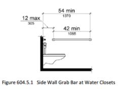
604.5.2 Rear Wall.
The rear wall grab bar shall be 36 inches (915 mm) long minimum and extend from the centerline of the water closet 12 inches (305 mm) minimum on one side and 24 inches (610 mm) minimum on the other side.
EXCEPTIONS: 1. The rear grab bar shall be permitted to be 24 inches (610 mm) long minimum, centered on the water closet, where wall space does not permit a length of 36 inches (915 mm) minimum due to the location of a recessed fixture adjacent to the water closet.
2. Where an administrative authority requires flush controls for flush valves to be located in a position that conflicts with the location of the rear grab bar, then the rear grab bar shall be permitted to be split or shifted to the open side of the toilet area.
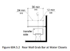
604.6 Flush Controls.
Flush controls shall be hand operated or automatic. Hand operated flush controls shall comply with 309. Flush controls shall be located on the open side of the water closet except in ambulatory accessible compartments complying with 604.8.2.
604.7 Dispensers.
Toilet paper dispensers shall comply with 309.4 and shall be 7 inches (180 mm) minimum and 9 inches (230 mm) maximum in front of the water closet measured to the centerline of the dispenser. The outlet of the dispenser shall be 15 inches (380 mm) minimum and 48 inches (1220 mm) maximum above the finish floor and shall not be located behind grab bars. Dispensers shall not be of a type that controls delivery or that does not allow continuous paper flow.
Advisory 604.7 Dispensers. If toilet paper dispensers are installed above the side wall grab bar, the outlet of the toilet paper dispenser must be 48 inches (1220 mm) maximum above the finish floor and the top of the gripping surface of the grab bar must be 33 inches (840 mm) minimum and 36 inches (915 mm) maximum above the finish floor.
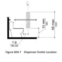
608.6 Shower Spray Unit and Water.
A shower spray unit with a hose 59 inches (1500 mm) long minimum that can be used both as a fixed-position shower head and as a hand-held shower shall be provided. The shower spray unit shall have an on/off control with a non-positive shut-off. If an adjustable-height shower head on a vertical bar is used, the bar shall be installed so as not to obstruct the use of grab bars. Shower spray units shall deliver water that is 120°F (49°C) maximum.
EXCEPTION: A fixed shower head located at 48 inches (1220 mm) maximum above the shower finish floor shall be permitted instead of a hand-held spray unit in facilities that are not medical care facilities, longterm care facilities, transient lodging guest rooms, or residential dwelling units.
Advisory 608.6 Shower Spray Unit and Water. Ensure that hand-held shower spray units are capable of delivering water pressure substantially equivalent to fixed shower heads.
609.1 General.
Grab bars in toilet facilities and bathing facilities shall comply with 609.
609.2 Cross Section.
Grab bars shall have a cross section complying with 609.2.1 or 609.2.2.
609.2.1 Circular Cross Section.
Grab bars with circular cross sections shall have an outside diameter of 1 1/4 inches (32 mm) minimum and 2 inches (51 mm) maximum.
609.2.2 Non-Circular Cross Section.
Grab bars with non-circular cross sections shall have a cross-section dimension of 2 inches (51 mm) maximum and a perimeter dimension of 4 inches (100 mm) minimum and 4.8 inches (120 mm) maximum.
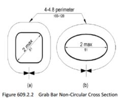
609.3 Spacing.
The space between the wall and the grab bar shall be 1 1/2 inches (38 mm). The space between the grab bar and projecting objects below and at the ends shall be 1 1/2 inches (38 mm) minimum. The space between the grab bar and projecting objects above shall be 12 inches (305 mm) minimum.
EXCEPTION: The space between the grab bars and shower controls, shower fittings, and other grab bars above shall be permitted to be 1 1/2 inches (38 mm) minimum.
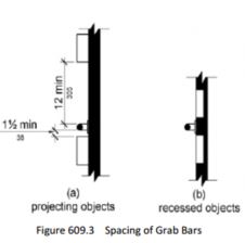
609.4 Position of Grab Bars.
Grab bars shall be installed in a horizontal position, 33 inches (840 mm) minimum and 36 inches (915 mm) maximum above the finish floor measured to the top of the gripping surface, except that at water closets for children's use complying with 604.9, grab bars shall be installed in a horizontal position 18 inches (455 mm) minimum and 27 inches (685 mm) maximum above the finish floor measured to the top of the gripping surface. The height of the lower grab bar on the back wall of a bathtub shall comply with 607.4.1.1 or 607.4.2.1.
609.5 Surface Hazards.
Grab bars and any wall or other surfaces adjacent to grab bars shall be free of sharp or abrasive elements and shall have rounded edges.
609.6 Fittings.
Grab bars shall not rotate within their fittings.
609.7 Installation.
Grab bars shall be installed in any manner that provides a gripping surface at the specified locations and that does not obstruct the required clear floor space.
609.8 Structural Strength.
Allowable stresses shall not be exceeded for materials used when a vertical or horizontal force of 250 pounds (1112 N) is applied at any point on the grab bar, fastener, mounting device, or supporting structure.
F216.1 General.
Signs shall be provided in accordance with F216 and shall comply with 703.
703.7 Symbols of Accessibility.
Symbols of accessibility shall comply with 703.7.
Symbols of accessibility and their background shall have a non-glare finish. Symbols of accessibility shall contrast with their background with either a light symbol on a dark background or a dark symbol on a light background.
Advisory 703.7.1 Finish and Contrast. Signs are more legible for persons with low vision when characters contrast as much as possible with their background. Additional factors affecting the ease with which the text can be distinguished from its background include shadows cast by lighting sources, surface glare, and the uniformity of the text and background colors and textures.
703.7.2.1 International Symbol of Accessibility.
The International Symbol of Accessibility shall comply with Figure 703.7.2.1.

This symbol is to be posted at the following locations:
At designated accessible parking spaces (F216.5)
- where a total of 5 or more parking spaces, including accessible parking spaces, are at a site (F216.5.1)
- van parking space must be signed as “van accessible”.(F216.5)
If the main entrance to a building is not accessible, the ISA and an arrow to be posted to direct to closest accessible entrance. (F216.6)
Accessible restrooms and bathing facilities.(F216.8)
Accessible Area of Refuge inside multi story buildings (F216.4.2)
Accessible means of egress out of a building (F216.4.3)
If an entrance or elevator is not accessible, the ISA and an arrow are to be posted to direct to closest accessible (F216.7)
903.1 General.
Benches shall comply with 903.
903.2 Clear Floor or Ground Space.
Clear floor or ground space complying with 305 shall be provided and shall be positioned at the end of the bench seat and parallel to the short axis of the bench.
903.3 Size.
Benches shall have seats that are 42 inches (1065 mm) long minimum and 20 inches (510 mm) deep minimum and 24 inches (610 mm) deep maximum.
903.4 Back Support.
The bench shall provide for back support or shall be affixed to a wall. Back support shall be 42 inches (1065 mm) long minimum and shall extend from a point 2 inches (51 mm) maximum above the seat surface to a point 18 inches (455 mm) minimum above the seat surface. Back support shall be 2 1/2 inches (64 mm) maximum from the rear edge of the seat measured horizontally.
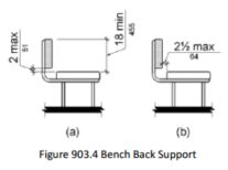
903.5 Height.
The top of the bench seat surface shall be 17 inches (430 mm) minimum and 19 inches (485 mm) maximum above the finish floor or ground.
903.6 Structural Strength.
Allowable stresses shall not be exceeded for materials used when a vertical or horizontal force of 250 pounds (1112 N) is applied at any point on the seat, fastener, mounting device, or supporting structure.
User Comments/Questions
Add Comment/Question