
Forest Service Trail Accessibility Guidelines
(FSTAG)
2013
All Trails and Constructed Features Addressed in the FSTAG and FSORAG that are constructed or altered within the National Forest System shall comply with the FSTAG and FSORAG.
_________________________________________________________________________
Contents
FSTAG - Scoping Requirements and Technical Provisions:
Contains the scoping requirements, definitions and technical specifications
Appendices:
Overview of FSTAG Implementation Process: A flowchart on how to apply the FSTAG one step at a time. (Best if printed in color.)
Federal Trail Data Standards: Trail Fundamentals
Federal Trail Data Standards: Class Matrix
Forest Service Recreation Site Development Scale Definitions
FSORAG Technical Provisions Referenced in the FSTAG’s Technical Provisions
7.0 APPLICATION
The Forest Service Trail Accessibility Guidelines (FSTAG) provides guidance for maximizing accessibility of trails in the National Forest System, while protecting the unique characteristics of their natural setting. The FSTAG and the Forest Service Outdoor Recreation Accessibility Guidelines (FSORAG) are the legally enforceable standards for use in outdoor recreation areas on the National Forest System for the facilities, routes, and features addressed in these guidelines. Although not legally enforceable outside of the National Forest System, the Guidelines may be used by other entities to define best practices for trails.
These guidelines have been updated to incorporate the supplement to the Architectural Barriers Act Accessibility Standards, the Outdoor Developed Area Accessibility Guidelines (ODAAG), developed by the Architectural and Transportation Barriers Compliance Board (U.S. Access Board). While they incorporate the U.S. Access Board’s ODAAG they also ensure the application of equivalent or higher guidelines, in order to comply with other existing Forest Service policies, including universal design, as well as agency terminology and processes.
All trails in the National Forest System that (1) are new or altered; (2) have a Federal Trail Data Standard (FTDS) designation Designed Use of Hiker/Pedestrian; and (3) connect directly to a trailhead or to a trail that currently substantially complies with the FSTAG, shall comply with the FSTAG. Where provided, associated constructed features (such as tent pads, fire rings and pit toilets) located along National Forest System trails shall comply with the Forest Service Outdoor Recreation Accessibility Guidelines (FSORAG).
Side trails or other routes to associated constructed features off a trail are not outdoor recreation access routes. Therefore, they are subject only to section 7 of the FSTAG and do not have to comply with the technical provisions in section 2.0 of the FSORAG that apply to outdoor recreation access routes.
Trailheads and the constructed features at trailheads shall also comply with the applicable technical provisions of the FSORAG and ABAAS. Routes connecting those facilities are to comply with the FSORAG outdoor recreation access route specifications.
These guidelines do not apply to maintenance work (routine or periodic repair of existing trails, recreation sites, or facilities). Where existing individual site features are altered but the floor or ground surface under or around them is not altered, the clear floor or ground space shall not be required to comply with surface and slope requirements.
The FSTAG and FSORAG became the National Forest System’s legal standard for all applicable facilities on May 26, 2006 with the final Federal Register publication of Forest Service Manuals 2330 and 2350. As stated in the Federal Register, these guidelines would be updated periodically to ensure they remain equal to or a higher standard than other guidelines and standards applicable to Federal agencies under the Architectural Barriers Act.
Construction or alteration of all facilities within the National Forest System that are not addressed in the FSORAG or FSTAG shall comply with the applicable requirements of the Architectural Barriers Act Accessibility Standards (ABAAS). The FSTAG, FSORAG and ABAAS are all available at http://www.fs.fed.us/recreation/accessibility/.
Boating and fishing facilities, swimming pools, play areas, sports arenas, miniature golf courses, and amusement parks, which are referred to as “recreation facilities” are addressed in Chapter 10 of the ABAAS (http:// www.access-board.gov).
7.1 Conditions for an Exception
Where one or more of the following conditions exists on a trail, an “exception” provided in the guidelines for that specific technical requirement can be used where that condition exists. The exception shall not be used on the portion of the trail where the condition does not exist. If no exception is provided for the technical requirement, no exception is allowed. All other appropriate design options should be considered before applying the exception.
Condition for an Exception 1. Where compliance with the technical provision is not practicable due to terrain.
Condition for an Exception 2. Where compliance with the technical provision would fundamentally alter the function or purpose of the facility, trail, or the setting.
Condition for an Exception 3. Where compliance with the technical provision cannot be accomplished with the prevailing construction practices.
Condition for an Exception 4. Where compliance is precluded because the cultural, historic, or significant natural features are eligible for protection under Federal, State, or local law by:
-
Endangered Species Act (16 U.S.C. §§ 1531 et seq.);
-
National Environmental Policy Act (42 U.S.C. §§ 4321 et seq.);
-
National Historic Preservation Act (16 U.S.C. §§ 470 et seq.);
-
Wilderness Act (16 U.S.C. §§ 1131 et seq.); or
-
Other Federal, State, or local law the purpose of which is to preserve threatened or endangered species; the environment; or archaeological, cultural, historical, or other significant natural features.
7.2 General Exceptions
The basis for the determination that General Exception 1 or General Exception 2 apply shall be documented and maintained with the records of the construction or alteration project. Documentation shall include the rationale for that determination, which conditions for exception and which exceptions apply, the date of the determination, and the name of the individuals who made the determination. There is no standard format for this documentation; each unit may develop its own format to meet its specific needs.
7.2.1 General Exception 1.
Where a condition in 7.1 prohibits full compliance with a specific requirement in 7.4 on a trail segment, that trail segment shall comply with the specific requirement to the maximum extent practicable.
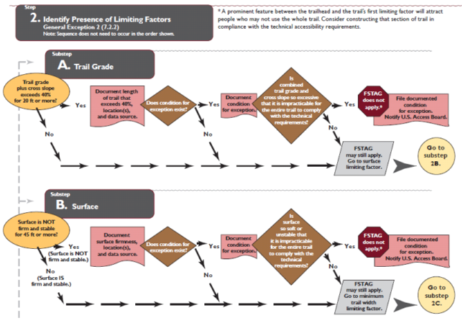
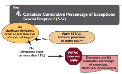
7.2.2 General Exception 2.
If after applying General Exception 1 it is determined that it is impracticable to provide a trail complying with 7.4, the trail shall not be required to comply with 7.4. Notification of this determination shall be sent to the Access Board. Website http://.access-board.gov/outdoor for optional use. For long-distance trails, this exception applies to the trail segments that are planned for construction or alteration in a given planning period, rather than over the entire length of the trail.
7.2.2.1 Determining Impracticability.
The use of General Exception 2 is reasonable where one or more conditions for an exemption in section 7.1 and at least one of the following limiting factors exist:
Limiting Factor 1. The combination of trail running slope (grade) and cross slope exceeds 1:2.5 (40 percent) for over a distance of 20 feet (6m).
Limiting Factor 2. The surface is not firm and stable for a distance of 45 feet or more (14 m).
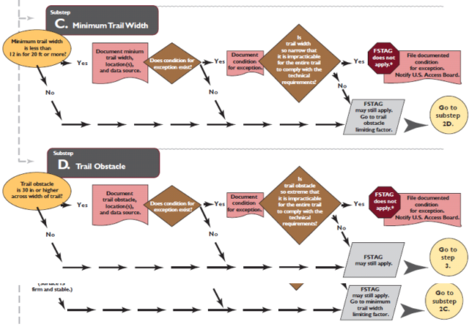
Limiting Factor 3. The minimum trail width is 12 inches (305 millimeters) or less for a distance of at least 20 feet (6100 mm).
Limiting Factor 4. A trail obstacle of at least 30 inches (770 mm) in height extends across the full width of the trail.
Limiting Factor 5. One or more conditions for an exception exist that result in significant deviations from the technical provisions of section 7.4.1 through 7.4.8 for over 15 percent of the length of the trail.
7.2.2.2 Extent of Impracticability.
Where General Exception 2 permits exemption of an entire trail from the requirements of section 7.4.1 through 7.4.8, it may be beneficial to construct a portion of the trail to meet the trail accessibility guidelines. Consider doing so especially if a prominent feature (such as a scenic view, waterfall, or other feature that would be of interest to visitors) is located between the trail terminus and the first extreme environmental barrier and there are few or no significant conditions requiring exceptions on that portion of the trail.
7.3 Definitions
All trail-related definitions used in the FSTAG are from the Forest Service Manual or Handbook, the Forest Service Infra Trails Module, Trail Assessment and Condition Survey (TRACS) reference materials, or are mandated by the Access Board.
“Accessible Trail” is a term to avoid.
The technical provisions in section 7.4 of the FSTAG allow for grades up to 12 percent. While such grades are understandable in challenging terrain as hiking paths selected by choice, the general public’s expectation of an “accessible” pathway is that it have a gentle grade and other uniform factors. In addition, most trails constructed under the FSTAG use exceptions to some extent in order to maintain the nature of the setting.
Therefore, a trail that has been constructed in accordance with the FSTAG should be advertised as a “trail that complies with the trail accessibility guidelines”, rather than as an “accessible trail”. Information concerning grades, etc. is to be posted along with other trail information on websites, trailhead signs, and so forth. Each visitor can then select the trail that best meets their recreation experience and expectations.
Alteration.
A change in the original purpose, intent, or function of a trail.
Camp Shelter.
A partially enclosed structure that provides campers and hikers cover from weather and that does not contain plumbing fixtures or kitchen appliances. Camp shelters are not cabins, which are typically larger and are required to comply with ABAAS section 806 for transient lodging where short term accommodations are provided.
-
Associated Constructed Feature. A constructed element associated with a trail that provides support for trail users, but is not a part of the trail tread. Examples include overnight shelters, toilets, fire rings, picnic tables, and tent pads. Refer to the FSORAG for the technical provisions for associated constructed features.
-
Trail Constructed Feature. A constructed feature that functions as part of the trail tread. Examples include puncheon, trail bridges, boardwalks, waterbars, and switchbacks. For a listing of trail constructed features, refer to the trail documentation available at http://www.fs.fed.us/recreation/programs/trail-management/index.shtml or available to Forest Service employees at http://fsweb.wo.fs.fed.us/rhwr/ibsc/tr-cost.shtml
Designed Use.
The “Managed Use” of a trail that requires the most demanding design, construction, and maintenance parameters. In conjunction with the applicable “Trail Class,” designed use determines which design parameters will apply to a trail. It is an FTDS term for the intended use that controls the geometric design of a trail and determines the level to which it should be maintained. There is only one “Designed Use” per trail or trail segment.
Federal Trail Data Standards (FTDS).
Standardized terminology that enable national, regional, and State trail managers, and the public, to use mutually understood terminology for recording, retrieving, and applying spatial and tabular information. FTDS make it easier for trail information to be accessed, exchanged, and used by more than one individual, agency, or group. The data standards are available at http://www.nps.gov/gis/trails/Doc2/Federal_Trail_Data_Standards_Final_20111108.pdf
Hiker/Pedestrian Trail.
A trail with a designed use of hiker/pedestrian that is designed, constructed, and maintained for hiker/pedestrian use.
Limiting Factor.
An extreme, uncorrectable environmental barrier that makes the trail beyond the barrier unreachable for many people with mobility limitations.
Maintenance.
Routine or periodic repair of trails or trail segments to restore them to the standards to which they were originally designed and built. Maintenance does not change the original purpose, intent, or design of a trail.
Managed Use.
An FTDS term for the mode(s) of travel for which a trail is actively managed. Managed uses are the specific types of trail use that are allowed by management decision or intent on a specific trail or portion of a trail. Each trail or trail segment may have more than one “Managed Use.” For example, a trail may be managed for both equestrian and hiker/pedestrian use in the summer and for cross-country skiing in the winter.
Outdoor Recreation Access Route (ORAR).
A continuous, unobstructed path for pedestrian use that connects elements in an outdoor recreation area such as a picnic area, campground, or trailhead.
Pit Toilet.
A primitive outhouse consisting of a toilet riser over a hole dug into the ground or receptacle to receive and naturally decompose human waste. Pit toilets are provided primarily for resource protection and are only constructed at recreation sites with a Recreation Site Development Scale level of 2 of less. A pit toilet riser may or may not be surrounded by walls and may or may not have a roof. A pit toilet may be permanently installed or may be moved from one location to another as the pit is filled or the area becomes severely impacted from use. Waste may be disposed of directly into the pit or may be composted.
Practicable.
Practicable in this context means the work can be completed within the limits of the applicable Conditions for an Exception and results in a useful improvement for all.
Prominent Feature.
A natural, cultural, or historic feature located along or adjacent to a trail that is determined by a trail designer or manager to have national, regional, or local distinction or significance. A prominent feature may be the focal point, main attraction, or destination of a trail, or it may simply be an interesting secondary feature. Examples include but are not limited to boulder outcrops, waterfalls, groupings of old or unique trees or other vegetation, vistas that may or may not be part of a developed overlook, and cultural or historic structures.
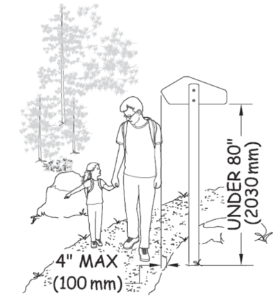
Protruding Object.
A constructed feature such as a sign that extends into the trail tread more than 4 inches (100 mm) between 27 inches (685 mm) and 80 inches (2030 mm) above the trail tread. Accessibility guidelines for protruding objects do not apply to naturally occurring objects, such as tree branches, or rock ledges. However, safety regulations or Forest Service construction and maintenance standards may define clear space and limit overhangs of natural protruding objects.
Provisions.
The sections of accessibility guidelines and standards that explain what is required for specific situations and facilities (parking, picnic tables, trails, etc.)
Recreation Site.
An area that is improved, developed, or otherwise identified for recreation and that has a development scale of 0, 1, 2, 3, 4, or 5 (See Forest Service Handbook 2309.13, Chapter 10 – Exhibit 01).
Reconstruction.
This term is not used in Federal accessibility guidelines or the FSTAG and FSORAG, even though it is used frequently by personnel who work in recreation and trails. For the purposes of the FSTAG and FSORAG, actions are categorized as construction, alteration, or maintenance.
Scoping Requirement.
Specifications of where, when, and how much of a constructed features detailed in the accessibility guidelines technical requirements must be met in order to comply with the FSTAG.
Slope.
The incline of a surface.
-
Cross Slope. The percentage of rise to length, which is the difference in elevation, when measuring the trail tread from edge to edge perpendicular to the direction of travel This may be expressed as the percentage of change in elevation or as a ratio of vertical distance to horizontal distance. The percentage is shown in parentheses in these guidelines.
-
Running Slope (Grade). The ascent or descent of a trail segment expressed as a percentage of its length, which is the difference in elevation of a section of a trail measured parallel to the predominant direction of travel. This may be expressed as a ratio of vertical distance to horizontal distance or as the percentage of change in elevation. The percentage is shown in parentheses in these guidelines.
Surface.
The top layer of a trail.
-
Firm. A firm surface resists deformation by indentations. During the planning process, firmness must be evaluated for noticeable distortion or compression during the seasons for which the surface is managed, under normally occurring weather conditions.
-
Stable. A surface is not permanently affected by expected weather conditions and can sustain normal wear and tear from the expected use(s) of the area, between planned maintenance.
Technical Requirements.
Are the specific numbers, conditions, and measurements that are required to be achieved (percent that must comply, dimensions, reach ranges, grades, trail width, etc.).
Trail.
For purposes of the FSTAG and FSORAG, a trail is a pedestrian route developed primarily for outdoor recreational hiking purposes. A pedestrian route provided primarily to connect elements, spaces, or facilities within a site is not a trail; it is an outdoor recreation access route (ORAR).
Trail Class.
The prescribed scale of development for a trail, representing its intended design and management standards.
Trail Grade.
The ascent or descent of a trail segment expressed as a percentage of its length. When expressed as a ratio of rise to length to the term used is running slope.
Trailhead.
For the purpose of the FSTAG a trailhead is an outdoor space that is designated by the entity responsible for administering or maintaining the trail to serve as a primary access point to the trail. The simple junction of two or more trails, or the undeveloped junction of a trail and a road, is not a trailhead.
Trail Segment.
The portion of a trail being planned, evaluated, or constructed.
Trail Tread.
The portion of a trail upon which traffic moves.
Trail Terminus.
For the purpose of the FSTAG the trail terminus is the beginning or ending point of a trail or trail segment, where a trail assessment or trail work begins or ends.
Tread Width.
The visible trail surface measured perpendicular to the direction of travel.
-
Clear Tread Width. The width of the usable trail tread and adjacent usable surface.
-
Minimum Tread Width. The width of the usable part of the tread width at the narrowest point on a trail.
-
Minimum Trail Width. The width of the trail tread and the adjacent usable surface at the narrowest point on a trail.
Wheelchair.
A device, including one that is a battery-powered, that is designed solely for use by a mobility-impaired person for locomotion and that is suitable for use in an indoor pedestrian area. A person whose disability requires use of a wheelchair or mobility device may use a wheelchair or mobility device that meets both parts of this definition anywhere foot travel is permitted (per 36 CFR 212, FSM 2350, and in Federally designated wilderness under ADA Title V, section 508c).
7.4 Technical Provisions
General: Trails shall comply with 7.4.
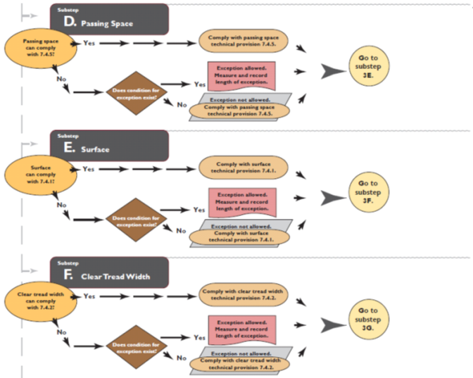
7.4.1 Surface.
The trail tread surface, including resting intervals and passing spaces, shall be both firm and stable.
7.4.2 Clear Tread Width.
The clear tread width of the trail shall be at least 36 inches (915 mm).
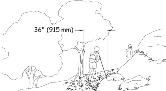
EXCEPTION: Where a condition for an exception prevents achieving the required width, the clear tread width may be reduced to 32 inches (815 mm) minimum. If the condition for an exception prevents achieving the reduced width of 32 inches, comply to the extent practicable.
7.4.3 Slope.
Trail running slopes (grades) and cross slopes shall comply with sections 7.4.3.1 and 7.4.3.2.
7.4.3.1 Running Slope (Grade).
The running slope (grade) of trail segments shall comply with this section and shall be consistent over the distances cited.
-
Trail running slope (grade) of up to 1:20 (5 percent) is permitted for any distance.
-
The running slope of any segment of a trail shall not be steeper than 1:8 (12 percent).
-
No more than 30 percent of the total trail length may exceed a running slope (grade) of 1:12 (8.33 percent).
-
Where the running slope (grade) of a segment of a trail is steeper than 1:20 (5 percent), the maximum length of the segment shall be in accordance with Table 7.4.3.1, and a resting interval complying with 7.4.4 shall be provided at each end of the segment.
Table 7.4.3.1 Trail Running Slope (Grade) and Resting Intervals
|
Running Slope of Trail Segment |
Maximum Length of Segment Between Resting Intervals |
|
| Steeper Than | But Not Steeper Than | |
|
1:20 (5 percent) |
1:12 (8.33 percent) |
200 feet (61 m) |
|
1:12 (8.33 percent) |
1:10 (10 percent) |
30 feet (9 m) |
|
1:10 (10 percent) |
1:8 (12 percent) |
10 feet (3050 mm) |
The cross slope shall not exceed 1:20 (5 percent). Where the surface is paved or is elevated above the natural ground, the cross slope shall not be steeper than 1:48 (2 percent).
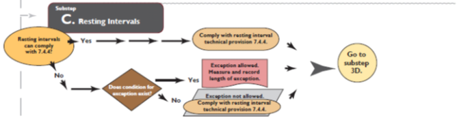
7.4.4 Resting Intervals.
Resting intervals shall comply with 7.4.4. Where the trail grade exceeds 1:20 (5 percent), resting intervals shall be provided as specified in Table 7.4.3.1.
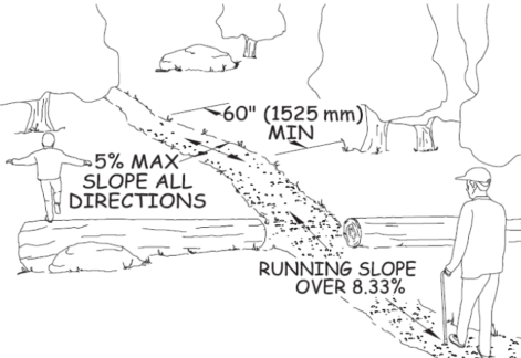
The resting interval length shall be 60 inches (1525 mm) long minimum.
Where resting intervals are provided within the trail tread, resting intervals shall be at least as wide as the widest segment of the trail tread leading to the resting interval. Where resting intervals are provided adjacent to the trail tread, the resting interval clear width shall be 36 inches (915 mm) minimum.
The slope of a resting interval shall not exceed 1:20 (5 percent) in any direction. Where the surface is paved or is elevated above the natural ground, the slope shall not be steeper than 1:48 (2 percent) in any direction.
Where resting intervals are provided adjacent to the trail tread, a turning space complying with ABAAS section 304.3.2 shall be provided. Vertical alignment between the trail tread, turning space, and resting interval shall be nominally level. The trail tread, turning space, and resting interval may overlap.
7.4.5 Passing Spaces.
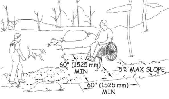
Trails with a clear tread width less than 60 inches (1525 mm) shall provide passing spaces complying with 7.4.5 at intervals of 1000 feet (300 m) maximum. A passing space must also be provided at the end of any segment of trail that meets the requirements of 7.4, if the full length of the trail does not meet the requirements. Passing spaces and resting intervals may coincide or overlap.
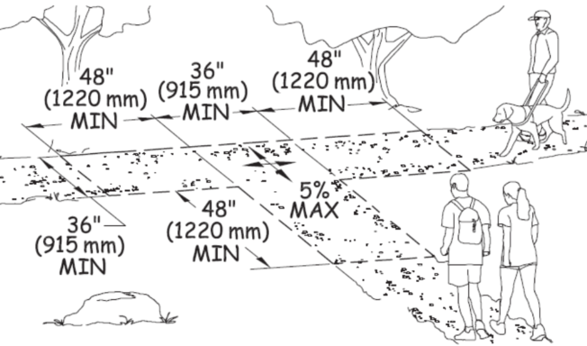
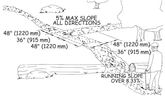
The passing space shall be either:
-
A space 60 inches (1525 mm) minimum by 60 inches (1525 mm) minimum; or
-
The intersection of two trails providing a T-shaped space complying with ABAAS section 304.3.2 where the base and the arms of the T-shaped space extend 48 inches (1220 mm) minimum beyond the intersection. Vertical alignment at the intersection of the trails that form the T-shaped space shall be nominally level.
The cross slope of a passing space shall not exceed 1:20 (5 percent) in any direction.
7.4.5.3 Non-complying Segment Ends.
Where a segment of the trail does not comply with 7.4, a passing space shall be located at the end of each adjacent trail segment that does comply with 7.4.
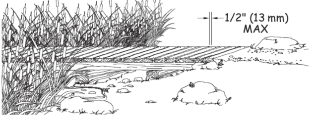
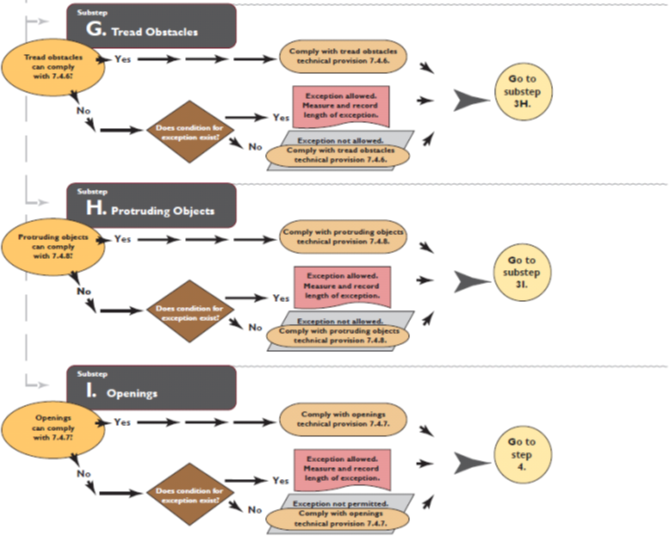
7.4.6 Tread Obstacles.
Tread obstacles on trails shall not exceed 2 inches (50 mm) in height measured vertically to the highest point. Where the trail surface is paved or is elevated above the natural ground, tread obstacles shall not exceed ½ inch (13 mm) in height measured vertically to the highest point.
7.4.7 Openings.
Openings in trail tread surfaces, trail resting spaces, and trail passing spaces shall be small enough to prevent passage of a 1/2 inch- (13 mm-) diameter sphere. Where possible, elongated openings should be placed perpendicular, or as close to perpendicular as possible, to the dominant direction of travel.
Exception: Where openings that do not permit the passage of a ½ inch (6.4 mm) sphere cannot be provided due to a condition for an exception, openings that do not permit passage of a ¾ inch (19 mm) sphere shall be permitted.
7.4.8 Protruding Objects.
Constructed features, including signs, shall not extend into the trail tread more than 4 inches (100 mm) between 27 inches (685 mm) and 80 inches (2030 mm) above the surface of the trail.
7.4.9 Trail Facilities.
Where provided on trails, facilities shall comply with the applicable provisions of the FSORAG. ORARs are not required at or between facilities on trails.
Exception. When the surface of the required clear ground space for trail facilities is not paved or is not elevated above the natural ground, slopes not steeper than 1:20 (5 percent) shall be permitted where necessary for drainage.
7.4.10 Trailheads.
Trailheads shall comply with 7.4.10.
7.4.10.1 Outdoor Constructed Features.
Where provided within trailheads each outdoor constructed features such as parking spaces, toilets, or camp sites shall comply with the applicable portions of the FSORAG and ABAAS.
7.4.10.2 Outdoor Recreation Access Routes (ORARs).
At least one outdoor recreation access route complying with FSORAG section 2.0 shall connect the following places at trailheads:
-
Accessible parking spaces or other arrival point;
-
Starting point of the trail; and
-
Accessible outdoor constructed features, elements, spaces, and facilities within the trailhead.
Exception 1. In alterations to existing trailheads, where a condition for exception prohibits compliance with a technical provision, the ORAR shall comply with FSORAG 2.0 to maximum extent practicable.
Exception 2. Where elements, spaces, or outdoor constructed features are altered at trailheads but the circulation path is not altered, an outdoor recreation access route shall not be required.
7.4.11 Trailhead Signs.
Where new trailhead information signs are provided at trailheads on newly constructed or altered trails, they shall comply with 7.4.11.
Trailhead signs shall be located centered at the back of a 30- by 48-inch (760- by 1,220-millimeter) minimum clear floor or ground space. The clear space shall not overlap the trail width but may overlap a resting space or passing space. The slope of the clear space shall not exceed 1:20 (5 percent) in any direction.
Where new trail information signs are provided at trailheads on newly constructed or altered trails, regardless of whether the trail is accessible, the signs shall include at minimum the following information:
-
Length of the trail or trail segment
-
Surface type
-
Typical and minimum tread width
-
Typical and maximum running slope
-
Typical and maximum cross slope
-
A statement that the posted information reflects the condition of the trail when it was constructed or assessed, including the date of the construction or assessment
Where more extensive trail information is provided (e.g., an aerial map of the trail and related facilities), the location of specific trail features and obstacles that do not comply with the technical provisions in 7.4 should be identified and a profile of the trail grade should be included.
If materials need to be obtained from or manipulated on a sign or kiosk, the sign or kiosk shall be designed to meet the reach ranges in section 308 of the ABAAS.
7.4.12 Gates and Barriers.
Where gates or barriers are constructed to control access to trails, gates and barriers shall comply with 7.4.12.
Gate openings and openings in barriers for hiker passage shall provide a clear width of 36 inches (915 mm), complying with ODAAG, section 1017.3 Clear Tread Width.
Overview of FSTAG Implementation Process:
A flowchart on how to apply the FSTAG one step at a time. (Best if printed in color.)
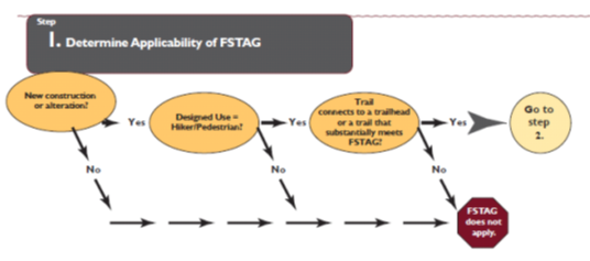

**Refer to FSTAG for detailed instructions, definitions, and technical provisions 7.0 through 7.3.
APPENDIX A: Federal Trail Data Standards (FTDS) – Trail Fundamentals
11/08/2011
Trail Type ◼ Trail Class ◼ Managed Use ◼ Designed Use
The Federal Trail Fundamentals include four concepts that are the cornerstones of effective trail planning and management:
-
Trail Type
-
Trail Class
-
Managed Use
-
Designed Use
Identify the four Trail Fundamentals for each trail or trail segment based on applicable land management plan direction, travel management decisions, trail-specific decisions, and other related direction.
Trail Fundamentals provide an integrated means to consistently record and communicate the intended design and management guidelines for trail design, construction, maintenance and use.
Trail Type
A category that reflects the predominant trail surface and general mode of travel accommodated by a trail.
There are three Trails Types:
Standard/Terra Trail: A trail that has a surface consisting predominantly of the ground and that is designed and managed to accommodate use on that surface.
Snow Trail: A trail that has a surface consisting predominantly of snow or ice and that is designed and managed to accommodate use on that surface.
Water Trail: A trail that has a surface consisting predominantly of water (but may include land-based portages) and that is designed and managed to accommodate use on that surface.
This management concept allows managers to identify trail-specific Design Parameters or technical specifications, management needs, and the cost of managing the trail for particular uses and/or seasons by trail or trail segment.
1. Inventory trails and identify the appropriate Design Parameters or technical specifications, management needs, and management costs for trail using the Trail Types.
2. Identify only one Trail Type per trail.
3. Identify the Trail Type for each trail based on applicable land management plan direction, travel management decisions, trail-specific decisions, and other related direction.
4. Inventory both trails and Trail Types when two trails overlap, for example, when a Snow Trail overlaps a Standard Terra Trail.
Trail Class
The prescribed scale of development for a trail, representing its intended design and management standards.
Trail Classes are general categories reflecting trail development scale, arranged along a continuum.
There are five Trail Classes, ranging from the least developed (Trail Class 1) to the most developed (Trail Class 5):
Trail Class 1: Minimally Developed
Trail Class 2: Moderately Developed
Trail Class 3: Developed
Trail Class 4: Highly Developed
Trail Class 5: Fully Developed
Use Trail Classes to inventory trails and to identify the applicable Design Parameters or technical specifications and the costs for meeting trail management standards.
1. Identify only one Trail Class per trail or trail segment.
2. Trail Class descriptors reflect typical attributes of trails in each class.Local deviations from any Trail Class descriptor may be established based on trail-specific conditions, topography, or other factors, provided that the deviations are consistent with the general intent of the applicable Trail Class.
3. There is a direct relationship between Trail Class and Managed Uses: generally, one cannot be determined without consideration of the other.
4. Identify the appropriate Trail Class for each trail or trail segment based on the management intent in the applicable land management plan, travel management decisions, trail-specific decisions, and other related direction. Apply the Trail Class that most closely reflects the management intent for the trail or trail segment, which may or may not reflect the current condition of the trail.
For specifics on each Trail Class, refer to the National Trail Management Class matrix.
Managed Use
A mode of travel that is actively managed and appropriate on a trail, based on its design and management.
1. Managed Use indicates management intent to accommodate a specific use.
2. There can be more than one Managed Use per trail or trail segment.
3. The Managed Uses for a trail are usually a small subset of all the allowed uses on the trail, that is, uses that are allowed unless specifically prohibited.For example, on a trail that is closed to all motorized use but open to all non-motorized use, the Managed Uses could be Hiker/Pedestrian and Pack and Saddle.The allowed uses, however, would also include bicycles and all other non-motorized uses.
4. Identify the Managed Uses for each trail or trail segment based on applicable land management plan direction, travel management decisions, trail-specific decisions, and other related direction.
5. There is a direct relationship between Managed Use and Trail Class: generally, one cannot be determined without consideration of the other. Not all Trail Classes are appropriate for all Managed Uses. For guidance on the potential appropriateness of each Trail Class to each Managed Use, refer to agency-specific guidelines and reference material.
Designed Use
The Managed Use of a trail that requires the most demanding design, construction, and maintenance parameters and that, in conjunction with the applicable Trail Class, determines which Design Parameters or technical specifications will apply to a trail.
1. There is only one Designed Use per trail or trail segment.Although a trail or trail segment may have more than one Managed Use and numerous uses may be allowed, only one Managed Use is identified as the design driver or Designed Use.
2. Determine the Designed Use for a trail or trail segment from the Managed Uses identified for that trail.making this determination, consider all Managed Uses that occur during all seasons of use of the trail or trail segment.Assess any essential or limiting geometry for the Managed Uses of the trail or trail segment to determine whether any trail-specific adjustments are necessary to the applicable Design Parameters or technical specifications.
a. In some situations, when there is more than one Managed Use identified for a trail, the Designed Use may be readily apparent. For example, on a trail with Managed Uses of all-terrain vehicle and Motorcycle, all-terrain vehicle use would be the Designed Use because this use requires wider tread widths and has lower tolerances for surface obstacles and maximum trail grades.
b. In other situations involving more than one Managed Use, the Designed Use may not be readily apparent, as is often the case when there are fewer differences between the applicable sets of Design Parameters than in the example above. For example, on a trail that is actively managed for hiker and pedestrian, pack and saddle, and bicycle use, pack and saddle use would likely be the Designed Use because of the three Managed Uses, pack and saddle use generally has the most limiting design requirements. While the Bicycle Design Parameters are very similar to the Pack and Saddle Design Parameters, the Design Parameters or technical specifications for this trail may need to be adjusted to accommodate bicycles.
Designed Use / Managed Use Types*
Hiker / Pedestrian
Pack and Saddle
Bicycle
Motorcycle
All Terrain Vehicle
Four-Wheel Drive Vehicle > 50” in Width
Cross-Country Ski
Dog Sled
Snowshoe
Snowmobile
Motorized Watercraft
Non-Motorized Watercraft
* Refer to agency-specific guidance regarding which of the Designed Uses and Managed Uses listed above are being used by a particular agency.
APPENDIX B: Federal Trail Data Standards – Class Matrix
11/08/2011
Trail Classes are general categories reflecting trail development scale, arranged along a continuum. The Trail Class identified for a trail prescribes its development scale, representing its intended design and management standards.1 Local deviations from any Trail Class descriptor may be established based on trail-specific conditions, topography, or other factors, provided that the deviations do not undermine the general intent of the applicable Trail Class.
Identify the appropriate Trail Class for each trail or trail segment based on the management intent in the applicable land management plan, travel management direction, trail-specific decisions, and other related direction. Apply the Trail Class that most closely matches the management intent for the trail or trail segment, which may or may not reflect the current condition of the trail.
|
Trail Attributes |
Trail Class 1 Minimally Developed |
Trail Class 2 Moderately Developed |
Trail Class 3 Developed |
Trail Class 4 Highly Developed |
Trail Class 5 Fully Developed |
|
Tread & Traffic Flow |
• Tread intermittent and often indistinct. • May require route finding. • Single lane, with no allowances constructed for passing. • Pre-dominantly native materials. |
• Tread continuous and discernible, but narrow and rough. • Single lane, with minor allowances constructed for passing. • Typically native materials. |
• Tread continuous and obvious. • Single lane, with allowances constructed for passing where required by traffic volumes in places where there is no reasonable opportunity to pass. • Native or imported materials. |
• Tread wide and relatively smooth , with few irregularities. • Single lane, with allowances constructed for passing where required by traffic volumes in places where there is no reasonable opportunity to pass. • Double lane where traffic volumes are high and passing is frequent. • Native or imported materials. • May be hardened. |
• Tread wide, firm, stable, and generally uniform • Single lane, with frequent turnouts where traffic volume is low to moderate. • Double lane where traffic volume is moderate to high. • Commonly hardened with asphalt or other imported material. |
| Obstacles |
• Obstacles common, naturally occurring, often substantial , and intended to provide increased challenge. • Narrow passages; brush, steep grades, rocks and logs present. |
• Obstacles may be common, substantial, and intended to provide increased challenge. • Blockages cleared to define route and protect resources. • Vegetation may encroach into trailway. |
• Obstacles may be common, but not substantial or intended to provide challenge. • Vegetation cleared outside of trailway. |
• Obstacles infrequent and insubstantial . • Vegetation cleared outside of trailway. |
• Obstacles not present • Grades typically < 8% |
|
Constructed Features & Trail Elements |
• Structures minimal to non-existent. • Drainage typically provided without structures. • Natural fords. • Typically no bridges. |
• Structures of limited size, scale, and quantity; typically constructed of native materials. • Structures adequate to protect trail infrastructure and resources. • Natural fords. • Bridges as needed for resource protection and appropriate access. |
• Structures may be common and substantial; constructed of imported or native materials. • Natural or constructed fords. • Bridges as needed for resource protection and appropriate access. |
• Structures frequent and substantial; typically constructed of imported materials. • Constructed or natural fords. • Bridges as needed for resource protection and user convenience. • Trailside amenities may be present. |
• Structures frequent or continuous; typically constructed of imported materials. • May include bridges, boardwalks, curbs, handrails, trailside amenities, and similar features. |
| Signs2 |
• Route identification signing limited to junctions. • Route markers present when trail location is not evident. • Regulatory and resource protection signing infrequent. • Destination signing, unless required, generally not present. • Information and interpretive signing generally not present. |
• Route identification signing limited to junctions. • Route markers present when trail location is not evident. • Regulatory and resource protection signing infrequent. • Destination signing typically infrequent outside of wilderness; generally not present in wilderness areas. • Information and interpretive signing uncommon. |
• Route identification signing at junctions and as needed for user reassurance. • Route markers as needed for user reassurance . • Regulatory and resource protection signing may be common. • Destination signing likely outside of wilderness; generally not present in wilderness areas . • Information and interpretive signs may be present outside of wilderness . |
• Route identification signing at junctions and as needed for user reassurance. • Route markers as needed for user reassurance. • Regulatory and resource protection signing common. • Destination signing common outside of wilderness; generally not present in wilderness areas. • Information and interpretive signs may be common outside wilderness areas. • Accessibility information likely displayed at trailhead. |
• Route identification signing at junctions and for user reassurance. • Route markers as needed for user reassurance. • Regulatory and resource protection signing common. • Destination signing common. • Information and interpretive signs common. • Accessibility information likely displayed at trailhead. |
|
Typical Recreation Environs & Experience3 |
• Natural and unmodified. • ROS: Typically Primitive to Roaded Natural. • WROS: Typically Primitive to Semi-Primitive . |
• Natural and essentially unmodified. • ROS: Typically Primitive to Roaded Natural. • WROS: Typically Primitive to Semi-Primitive. |
• Natural and primarily unmodified. • ROS: Typically Primitive to Roaded Natural. • WROS: Typically Semi-Primitive to Transition. |
• May be modified. • ROS: Typically Semi-Primitive to Rural. • WROS: Typically Portal or Transition. |
• May be highly modified. • Commonly associated with visitor centers or high-use recreation sites. • ROS: Typically Roaded Natural to Urban. • Generally not present in wilderness areas. |
1 For management standards, potential appropriateness of Trail Classes for Managed Uses, technical specifications by Trail Class and Designed Use, and other related guidance, refer to agency-specific guidelines and reference material.
2 For standards and guidelines for the use of signs and posters along trails, refer to agency-specific guidelines.
3 The National Trail Management Class matrix shows the combinations of Trail Class and Recreation Opportunity Spectrum (ROS) or Wilderness Recreation Opportunity Spectrum (WROS) settings that commonly occur, although trails in all Trail Classes may and do occur in all settings. For guidance on the application of the ROS and WROS, refer to agency-specific guidelines.
APPENDIX C: FSORAG Technical Provisions
Referenced in the FSTAG’s Technical Provisions
4.3.1 General.
Tent platforms are not required. Where provided, tent pads and tent platforms at single camping units shall comply with section 4.6 and shall be connected to an ORAR complying with section 2.0. Where camping units contain more than one tent pad or tent platform, at least 20 percent, but not less than two, of the tent pads or tent platforms shall comply with section 4.3.
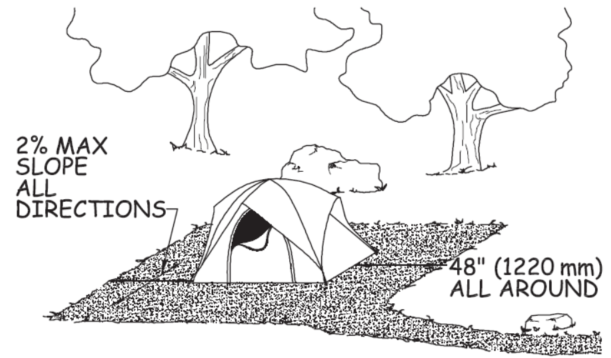
4.3.2 Clear Floor or Ground Space.
Tent pads and tent platforms shall have clear floor or ground space surrounding the tent that is at least 48 inches (1220 mm) wide. This space shall not overlap the ORAR.
Exception. Where a condition for exception in section 1.1 prohibits full compliance, the clear floor or ground space shall comply with 4.3.2 to the extent practicable.
4.3.3 Slope.
The slope of tent pads and tent platforms shall not exceed 1:48 (2 percent) in any direction.
Exception. When the surface is not paved or is not elevated above the natural ground, slopes not steeper than 1:33 (3 percent) shall be permitted where necessary for drainage.
4.3.4 Tent Pad or Platform Surface.
Tent pads and platforms shall have a surface that is firm and stable and is designed to allow use of tent stakes and other tent securing devices.
Exception. Where a condition for exception in section 1.1 prohibits full compliance, the surface shall comply with 4.3.4 to the extent practicable.
4.3.5 Transfer Height.
Tent platform surfaces that are not the same elevation as the ORAR shall be between 17 inches (430 mm) minimum and 19 inches (485 mm) maximum above the floor or ground surface adjacent to the ORAR to facilitate transfer from a wheelchair to the tent platform.
5.1.1 General.
Camp shelters at single camping units shall comply with 5.1. Where camping units contain more than one camp shelter, at least 20 percent, but not less than two, of the camp shelters shall comply with section 6.1. Camp shelters located on trails shall be connected to other constructed features in the unit by a trail complying with the FSTAG. Camp shelters located in a campground, not on a trail, shall be connected to other constructed features by an ORAR complying with section 2.0.
5.1.2 Level or Sloped Entry.
Camp shelters providing roll-in access shall have a level or sloped entry that complies with the FSORAG Outdoor Recreation Access Route technical provisions if the camp shelter is in a campground with a development level of 3 or higher. If the camp shelter is located off a trail, the sloped entry is to comply with the FSTAG Trail provisions.
5.1.3 Slope.
The slope of the surface of the clear floor or ground space inside the camp shelter shall not be steeper than 1:48 (2 percent) in all directions.
5.1.4 Turning Space.
Where the camp shelter floor is not elevated above the trail or ORAR, as applicable, a turning space complying with ABAAS section 304.3 shall be provided.
5.1.5 Floor Height.
Where the floor at the entrance to the camp shelter is elevated above the ground surface, the floor shall be 17 (430 mm) high minimum to 19 inches (485 mm) high maximum measured from the clear ground space to the floor surface inside the camp shelter.
5.1.6 Clear Floor or Ground Space.
A clear floor or ground space at least 36 inches (915 mm) by 48 inches (1220 mm) shall be provided parallel at the elevated entrance to the camp shelter. One full unobstructed side of the clear ground space shall adjoin or overlap the trail or ORAR, as applicable, or another clear ground space.
5.1.7 Surface.
The surface of the clear ground space shall be firm and stable.
5.1.8 Slope.
The slope of the surface of the clear ground space shall not be steeper than 1:48 in any direction.
Exception: When the surface is not paved or is not elevated above the natural ground, slopes not steeper than 1:20 (5 percent) shall be permitted where necessary for drainage.
5.1.9 Doors.
Where provided, doors shall comply with ABAAS section 404. The door shall not swing into or otherwise obstruct the clear floor or ground space or the turning space required by 5.1.4.
5.3.1 General.
Pit toilets may only be provided in FS recreation sites with a Recreation Site Development Scale level of 2 or less or at remote cabin locations. All pit toilets shall comply with section 5.3 and be connected to an ORAR complying with section 2.0. Where pit toilets are constructed in sites that are not accessed by motor vehicles, the pit toilet and all constructed features in the site shall be connected by trail segments complying with the FSTAG.
5.3.2 Turning Space and Clear Floor or Ground Space.
Turning space and clear floor or ground space complying with 5.3 shall be provided at pit toilets.
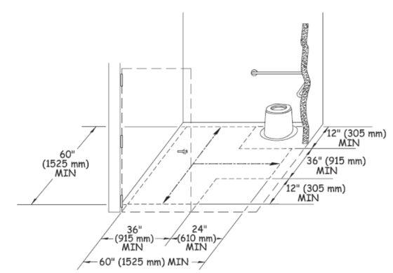
5.3.2.1 Size.
The clear floor or ground space shall be 60 inches (1525 mm) wide minimum measured parallel with the back of the pit toilet, and 56 inches (1420 mm) deep minimum measured parallel to the sides of the pit toilet. The turning space shall be at least 60 inches (1,525 millimeters) in diameter or T-shaped with a minimum 60- by 36-inch (1,525 by 915 millimeter) arm and a minimum 36-inch (915 millimeter) -wide by 24-inch (610 millimeter) -long base. The turning space and clear floor or ground space may overlap.
5.3.2.2 Surface.
The surface of the turning space and clear floor or ground space shall be firm and stable.
5.3.2.3 Slope.
The slope of the turning space and clear floor or ground space surface shall not be steeper than 1:48 (2 percent) in all directions.
Exception: When the surface is not paved or is not elevated above the natural ground, slopes not steeper than 1:20 (5 percent) shall be permitted where necessary for drainage
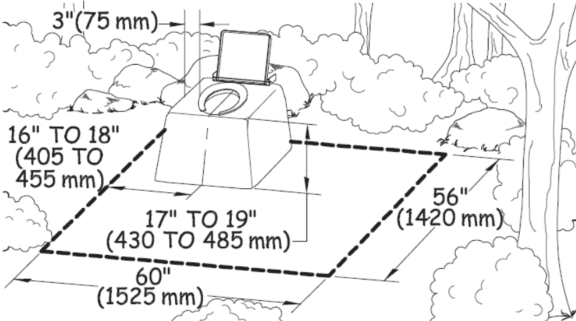
5.3.3.1 Height.
The total height of the toilet seat on the riser for a pit toilet shall be between 17 inches (430 mm) and 19 inches (485 mm) above the floor or ground surface.
5.3.3.2 Location Where Walls Provided.
Where walls or partitions are provided, the seat shall be positioned with a wall or partition to the rear and to one side of the seat for a left-hand or right-hand approach. The back of the riser shall be flush against the back wall. The centerline of the seat shall be 16 inches (405 mm) minimum to 18 inches (455 mm) maximum from the side wall or partition.
5.3.3.3 Location Where Walls Not Provided.
Where walls or partitions are not provided, the seat shall be positioned in a corner of the clear floor or ground space required by 5.3.2 for a left-hand or right-hand approach. The back of the seat shall be flush against the perimeter of the clear floor or ground space.
5.3.4 Grab Bars.
Where walls or partitions are provided, grab bars complying with ABAAS section 604.5 shall be provided.
Exception: Where the walls or partitions cannot support the force specified in ABAAS section 609.8, grab bars shall not be installed. In such cases, the riser shall have vertical or nearly vertical sides and a flat area on each side of the seat that is about 3 inches (75 millimeters) wide.
5.3.5 Doors.
Where provided, doors shall comply with ABAAS section 404. The door shall not swing into or otherwise obstruct the clear floor or ground space required by 5.3.2.1.
5.3.6 Entrance.
The entrance to the toilet shall be level with the surrounding surface.
Exception: Where bedrock, perma-frost or other environmental conditions prohibit a level entry or the toilet design (such as a composting toilet) necessitates a raised toilet structure, a sloped entry complying with the FSTAG provisions for a trail may connect the toilet entrance with the trail or ORAR. A 60 inch by 60 inch (1,220 millimeters by 1,220 millimeters) level landing must be provided outside the door to the toilet. Sloped entries do not require handrails.
APPENDIX D: Provisions of the Architectural Barriers Act Accessibility Standards (ABAAS)
that are referenced in the FSORAG Technical Provisions
The ABAAS are available at http://www.access-board.gov/ada-aba/aba-standards-gsa.cfm
304.1 General.
Turning space shall comply with 304.
304.3.1 Circular Space.
The turning space shall be a space of 60 inches (1525 mm) diameter minimum. The space shall be permitted to include knee and toe clearance complying with 306.
304.3.2 T-Shaped Space.
The turning space shall be a T-shaped space within a 60 inch (1525 mm) square minimum with arms and base 36 inches (915 mm) wide minimum. Each arm of the T shall be clear of obstructions 12 inches (305 mm) minimum in each direction and the base shall be clear of obstructions 24 inches (610 mm) minimum. The space shall be permitted to include knee and toe clearance complying with 306 only at the end of either the base or one arm.
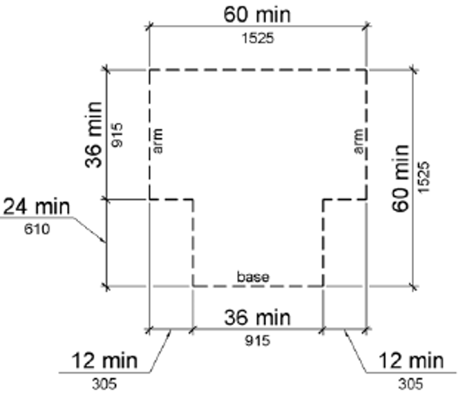
Figure 304.3.2 T-Shaped Turning Space
305.1 General.
Clear floor or ground space shall comply with 305.
305.2 Floor or Ground Surfaces.
Floor or ground surfaces of a clear floor or ground space shall comply with 302. Changes in level are not permitted.
EXCEPTION: Slopes not steeper than 1:48 shall be permitted.
305.3 Size.
The clear floor or ground space shall be 30 inches (760 mm) minimum by 48 inches (1220 mm) minimum.
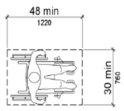
Figure 305.3 Clear Floor or Ground Space
305.4 Knee and Toe Clearance.
Unless otherwise specified, clear floor or ground space shall be permitted to include knee and toe clearance complying with 306.
305.5 Position.
Unless otherwise specified, clear floor or ground space shall be positioned for either forward or parallel approach to an element.
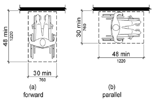
Figure 305.5 Position of Clear Floor or Ground Space
305.6 Approach.
One full unobstructed side of the clear floor or ground space shall adjoin an accessible route or adjoin another clear floor or ground space.
305.7 Maneuvering Clearance.
Where a clear floor or ground space is located in an alcove or otherwise confined on all or part of three sides, additional maneuvering clearance shall be provided in accordance with 305.7.1 and 305.7.2.
305.7.1 Forward Approach.
Alcoves shall be 36 inches (915 mm) wide minimum where the depth exceeds 24 inches (610 mm).
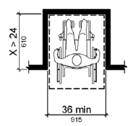
Figure 305.7.1 Maneuvering Clearance in an Alcove, Forward Approach
305.7.2 Parallel Approach.
Alcoves shall be 60 inches (1525 mm) wide minimum where the depth exceeds 15 inches (380 mm).
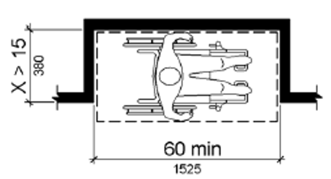
Figure 305.7.2 Maneuvering Clearance in an Alcove, Parallel Approach
306.1 General.
Where space beneath an element is included as part of clear floor or ground space or turning space, the space shall comply with 306. Additional space shall not be prohibited beneath an element but shall not be considered as part of the clear floor or ground space or turning space.
Advisory 306.1 General. Clearances are measured in relation to the usable clear floor space, not necessarily to the vertical support for an element. When determining clearance under an object for required turning or maneuvering space, care should be taken to ensure the space is clear of any obstructions.
306.2.1 General.
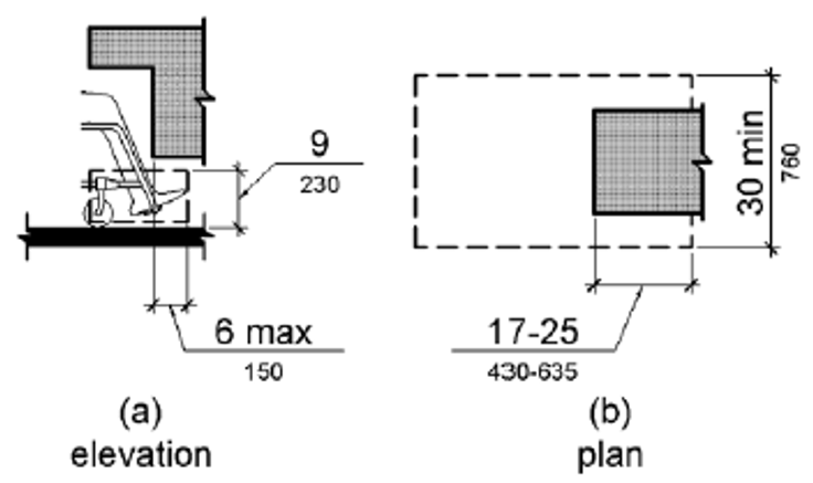
Space under an element between the finish floor or ground and 9 inches (230 mm) above the finish floor or ground shall be considered toe clearance and shall comply with 306.2.
306.2.2 Maximum Depth.
Toe clearance shall extend 25 inches (635 mm) maximum under an element.
306.2.3 Minimum Required Depth.
Where toe clearance is required at an element as part of a clear floor space, the toe clearance shall extend 17 inches (430 mm) minimum under the element.
306.2.4 Additional Clearance.
Space extending greater than 6 inches (150 mm) beyond the available knee clearance at 9 inches (230 mm) above the finish floor or ground shall not be considered toe clearance.
306.2.5 Width.
Toe clearance shall be 30 inches (760 mm) wide minimum.
306.3.1 General.
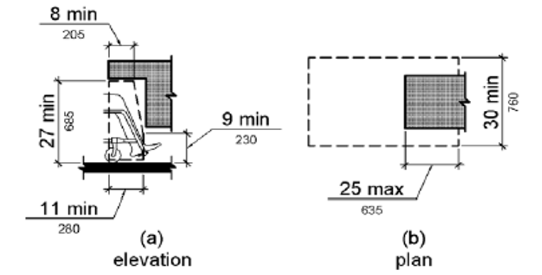
Space under an element between 9 inches (230 mm) and 27 inches (685 mm) above the finish floor or ground shall be considered knee clearance and shall comply with 306.3.
306.3.2 Maximum Depth.
Knee clearance shall extend 25 inches (635 mm) maximum under an element at 9 inches (230 mm) above the finish floor or ground.
306.3.3 Minimum Required Depth.
Where knee clearance is required under an element as part of a clear floor space, the knee clearance shall be 11 inches (280 mm) deep minimum at 9 inches (230 mm) above the finish floor or ground, and 8 inches (205 mm) deep minimum at 27 inches (685 mm) above the finish floor or ground.
306.3.4 Clearance Reduction.
Between 9 inches (230 mm) and 27 inches (685 mm) above the finish floor or ground, the knee clearance shall be permitted to reduce at a rate of 1 inch (25 mm) in depth for each 6 inches (150 mm) in height.
306.3.5 Width.
Knee clearance shall be 30 inches (760 mm) wide minimum.
308.1 General.
Reach ranges shall comply with 308.
308.2.1 Unobstructed.
Where a forward reach is unobstructed, the high forward reach shall be 48 inches (1220 mm) maximum and the low forward reach shall be 15 inches (380 mm) minimum above the finish floor or ground.
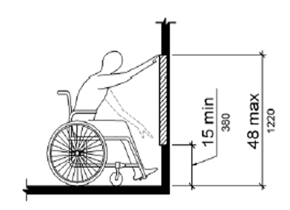
Figure 308.2.1 Unobstructed Forward Reach
308.2.2 Obstructed High Reach.
Where a high forward reach is over an obstruction, the clear floor space shall extend beneath the element for a distance not less than the required reach depth over the obstruction. The high forward reach shall be 48 inches (1220 mm) maximum where the reach depth is 20 inches (510 mm) maximum. Where the reach depth exceeds 20 inches (510 mm), the high forward reach shall be 44 inches (1120 mm) maximum and the reach depth shall be 25 inches (635 mm) maximum.
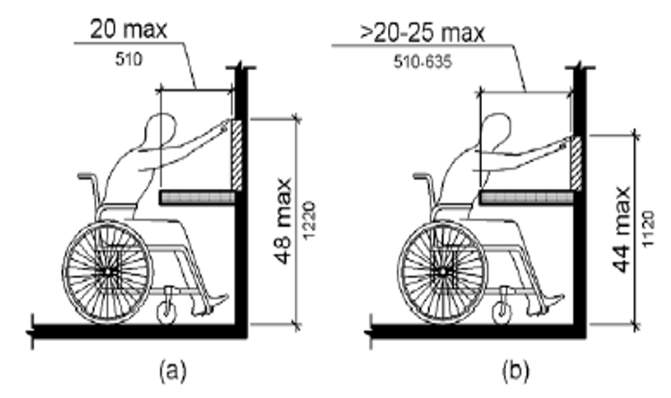
Figure 308.2.2 Obstructed High Forward Reach
308.3.1 Unobstructed.
Where a clear floor or ground space allows a parallel approach to an element and the side reach is unobstructed, the high side reach shall be 48 inches (1220 mm) maximum and the low side reach shall be 15 inches (380 mm) minimum above the finish floor or ground.
EXCEPTIONS: 1. An obstruction shall be permitted between the clear floor or ground space and the element where the depth of the obstruction is 10 inches (255 mm) maximum.
2. Operable parts of fuel dispensers shall be permitted to be 54 inches (1370 mm) maximum measured from the surface of the vehicular way where fuel dispensers are installed on existing curbs.
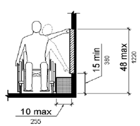
Figure 308.3.1 Unobstructed Side Reach
308.3.2 Obstructed High Reach.
Where a clear floor or ground space allows a parallel approach to an element and the high side reach is over an obstruction, the height of the obstruction shall be 34 inches (865 mm) maximum and the depth of the obstruction shall be 24 inches (610 mm) maximum. The high side reach shall be 48 inches (1220 mm) maximum for a reach depth of 10 inches (255 mm) maximum. Where the reach depth exceeds 10 inches (255 mm), the high side reach shall be 46 inches (1170 mm) maximum for a reach depth of 24 inches (610 mm) maximum.
EXCEPTIONS: 1. The top of washing machines and clothes dryers shall be permitted to be 36 inches (915 mm) maximum above the finish floor.
2. Operable parts of fuel dispensers shall be permitted to be 54 inches (1370 mm) maximum measured from the surface of the vehicular way where fuel dispensers are installed on existing curbs.
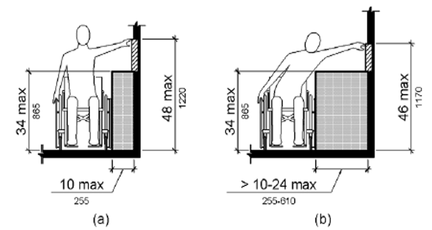
Figure 308.3.2 Obstructed High Side Reach
309.1 General.
Operable parts shall comply with 309.
309.2 Clear Floor Space.
A clear floor or ground space complying with 305 shall be provided.
309.3 Height.
Operable parts shall be placed within one or more of the reach ranges specified in 308.
309.4 Operation.
Operable parts shall be operable with one hand and shall not require tight grasping, pinching, or twisting of the wrist. The force required to activate operable parts shall be 5 pounds (22.2 N) maximum.
EXCEPTION: Gas pump nozzles shall not be required to provide operable parts that have an activating force of 5 pounds (22.2 N) maximum.
404.2.3 Doorways - Clear Width.
Door openings shall provide a clear width of 32 inches (815 mm) minimum. Clear openings of doorways with swinging doors shall be measured between the face of the door and the stop, with the door open 90 degrees. Openings more than 24 inches (610 mm) deep shall provide a clear opening of 36 inches (915 mm) minimum. There shall be no projections into the required clear opening width lower than 34 inches (865 mm) above the finish floor or ground. Projections into the clear opening width between 34 inches (865 mm) and 80 inches (2030 mm) above the finish floor or ground shall not exceed 4 inches (100 mm).
EXCEPTIONS: 1. In alterations, a projection of 5/8 inch (16 mm) maximum into the required clear width shall be permitted for the latch side stop.
2. Door closers and door stops shall be permitted to be 78 inches (1980 mm) minimum above the finish floor or ground.
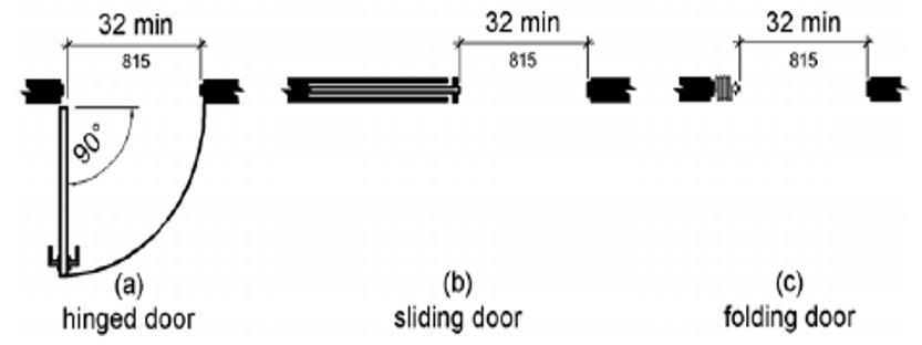
Figure 404.2.3 Clear Width of Doorways
404.2.7 Door and Gate Hardware.
Handles, pulls, latches, locks, and other operable parts on doors and gates shall comply with 309.4. Operable parts of such hardware shall be 34 inches (865 mm) minimum and 48 inches (1220 mm) maximum above the finish floor or ground. Where sliding doors are in the fully open position, operating hardware shall be exposed and usable from both sides.
User Comments/Questions
Add Comment/Question