ABA Accessibility Standard for GSA Facilities Pocket Guide
ABA CHAPTER 10: RECREATION FACILITIES
1001.1 Scope.
The provisions of Chapter 10 shall apply where required by Chapter 2 or where referenced by a requirement in this document.
Advisory 1001.1 Scope. Unless otherwise modified or specifically addressed in Chapter 10, all other requirements in this document apply to the design and construction of recreation facilities.
The requirements in 1011 through 1019 apply only to facilities constructed or altered by federal agencies or by non-federal entities on federal land on behalf of federal agencies pursuant to a concession contract, partnership agreement, or similar arrangement. See F201.4. The requirements in 1011 and 1019 allow for limitations and other constraints posed by the existing outdoor environment.
1002.1 General.
Amusement rides shall comply with 1002.
1002.2 Accessible Routes.
Accessible routes serving amusement rides shall comply with Chapter 4.
EXCEPTIONS: 1. In load or unload areas and on amusement rides, where compliance with 405.2 is not structurally or operationally feasible, ramp slope shall be permitted to be 1:8 maximum.
2. In load or unload areas and on amusement rides, handrails provided along walking surfaces complying with 403 and required on ramps complying with 405 shall not be required to comply with 505 where compliance is not structurally or operationally feasible.
1002.3 Load and Unload Areas.
A turning space complying with 304.2 and 304.3 shall be provided in load and unload areas.
1002.4 Wheelchair Spaces in Amusement Rides.
Wheelchair spaces in amusement rides shall comply with 1002.4.
1002.4.1 Floor or Ground Surface.
The floor or ground surface of wheelchair spaces shall be stable and firm.
1002.4.2 Slope.
The floor or ground surface of wheelchair spaces shall have a slope not steeper than 1:48 when in the load and unload position.
1002.4.3 Gaps.
Floors of amusement rides with wheelchair spaces and floors of load and unload areas shall be coordinated so that, when amusement rides are at rest in the load and unload position, the vertical difference between the floors shall be within plus or minus 5/8 inches (16 mm) and the horizontal gap shall be 3 inches (75 mm) maximum under normal passenger load conditions.
EXCEPTION: Where compliance is not operationally or structurally feasible, ramps, bridge plates, or similar devices complying with the applicable requirements of 36 CFR 1192.83(c) shall be provided.
1002.4.4 Clearances.
Clearances for wheelchair spaces shall comply with 1002.4.4.
EXCEPTIONS: 1. Where provided, securement devices shall be permitted to overlap required clearances.
2. Wheelchair spaces shall be permitted to be mechanically or manually repositioned.
3. Wheelchair spaces shall not be required to comply with 307.4.
1002.4.4.1 Width and Length.
Wheelchair spaces shall provide a clear width of 30 inches (760 mm) minimum and a clear length of 48 inches (1220 mm) minimum measured to 9 inches (230 mm) minimum above the floor surface.
1002.4.4.2 Side Entry.
Where wheelchair spaces are entered only from the side, amusement rides shall be designed to permit sufficient maneuvering clearance for individuals using a wheelchair or mobility aid to enter and exit the ride.
1002.4.4.3 Permitted Protrusions in Wheelchair Spaces.
Objects are permitted to protrude a distance of 6 inches (150 mm) maximum along the front of the wheelchair space, where located 9 inches (230 mm) minimum and 27 inches (685 mm) maximum above the floor or ground surface of the wheelchair space. Objects are permitted to protrude a distance of 25 inches (635 mm) maximum along the front of the wheelchair space, where located more than 27 inches (685 mm) above the floor or ground surface of the wheelchair space.
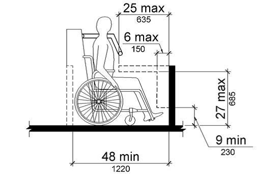
Figure 1002.4.4.3 Protrusions in Wheelchair Spaces in Amusement Rides
1002.4.5 Ride Entry.
Openings providing entry to wheelchair spaces on amusement rides shall be 32 inches (815 mm) minimum clear.
1002.4.6 Approach.
One side of the wheelchair space shall adjoin an accessible route when in the load and unload position.
1002.4.7 Companion Seats.
Where the interior width of the amusement ride is greater than 53 inches (1345 mm), seating is provided for more than one rider, and the wheelchair is not required to be centered within the amusement ride, a companion seat shall be provided for each wheelchair space.
1002.4.7.1 Shoulder-to-Shoulder Seating.
Where an amusement ride provides shoulder-to-shoulder seating, companion seats shall be shoulder-to-shoulder with the adjacent wheelchair space.
EXCEPTION: Where shoulder-to-shoulder companion seating is not operationally or structurally feasible, compliance with this requirement shall be required to the maximum extent practicable.
1002.5 Amusement Ride Seats Designed for Transfer.
Amusement ride seats designed for transfer shall comply with 1002.5 when positioned for loading and unloading.
1002.5.1 Clear Floor or Ground Space.
A clear floor or ground space complying with 305 shall be provided in the load and unload area adjacent to the amusement ride seats designed for transfer.
1002.5.2 Transfer Height.
The height of amusement ride seats designed for transfer shall be 14 inches (355 mm) minimum and 24 inches (610 mm) maximum measured from the surface of the load and unload area.
1002.5.3 Transfer Entry.
Where openings are provided for transfer to amusement ride seats, the openings shall provide clearance for transfer from a wheelchair or mobility aid to the amusement ride seat.
1002.5.4 Wheelchair Storage Space.
Wheelchair storage spaces complying with 305 shall be provided in or adjacent to unload areas for each required amusement ride seat designed for transfer and shall not overlap any required means of egress or accessible route.
1002.6 Transfer Devices for Use with Amusement Rides.
Transfer devices for use with amusement rides shall comply with 1002.6 when positioned for loading and unloading.
Advisory 1002.6 Transfer Devices for Use with Amusement Rides. Transfer devices for use with amusement rides should permit individuals to make independent transfers to and from their wheelchairs or mobility devices. There are a variety of transfer devices available that could be adapted to provide access onto an amusement ride. Examples of devices that may provide for transfers include, but are not limited to, transfer systems, lifts, mechanized seats, and custom designed systems. Operators and designers have flexibility in developing designs that will facilitate individuals to transfer onto amusement rides. These systems or devices should be designed to be reliable and sturdy.
Designs that limit the number of transfers required from a wheelchair or mobility device to the ride seat are encouraged. When using a transfer device to access an amusement ride, the least number of transfers and the shortest distance is most usable. Where possible, designers are encouraged to locate the transfer device seat no higher than 17 to 19 inches (430 to 485 mm) above the load and unload surface. Where greater distances are required for transfers, providing gripping surfaces, seat padding, and avoiding sharp objects in the path of transfer will facilitate the transfer. Where a series of transfers are required to reach the amusement ride seat, each vertical transfer should not exceed 8 inches (205 mm).
1002.6.1 Clear Floor or Ground Space.
A clear floor or ground space complying with 305 shall be provided in the load and unload area adjacent to the transfer device.
1002.6.2 Transfer Height.
The height of transfer device seats shall be 14 inches (355 mm) minimum and 24 inches (610 mm) maximum measured from the load and unload surface.
1002.6.3 Wheelchair Storage Space.
Wheelchair storage spaces complying with 305 shall be provided in or adjacent to unload areas for each required transfer device and shall not overlap any required means of egress or accessible route.
1003.1 General.
Recreational boating facilities shall comply with 1003.
1003.2 Accessible Routes.
Accessible routes serving recreational boating facilities, including gangways and floating piers, shall comply with Chapter 4 except as modified by the exceptions in 1003.2.
1003.2.1 Boat Slips.
Accessible routes serving boat slips shall be permitted to use the exceptions in 1003.2.1.
EXCEPTIONS: 1. Where an existing gangway or series of gangways is replaced or altered, an increase in the length of the gangway shall not be required to comply with 1003.2 unless required by 202.4.
2. Gangways shall not be required to comply with the maximum rise specified in 405.6.
3. Where the total length of a gangway or series of gangways serving as part of a required accessible route is 80 feet (24 m) minimum, gangways shall not be required to comply with 405.2.
4. Where facilities contain fewer than 25 boat slips and the total length of the gangway or series of gangways serving as part of a required accessible route is 30 feet (9145 mm) minimum, gangways shall not be required to comply with 405.2.
5. Where gangways connect to transition plates, landings specified by 405.7 shall not be required.
6. Where gangways and transition plates connect and are required to have handrails, handrail extensions shall not be required. Where handrail extensions are provided on gangways or transition plates, the handrail extensions shall not be required to be parallel with the ground or floor surface.
7. The cross slope specified in 403.3 and 405.3 for gangways, transition plates, and floating piers that are part of accessible routes shall be measured in the static position.
8. Changes in level complying with 303.3 and 303.4 shall be permitted on the surfaces of gangways and boat launch ramps.
1003.2.2 Boarding Piers at Boat Launch Ramps.
Accessible routes serving boarding piers at boat launch ramps shall be permitted to use the exceptions in 1003.2.2.
EXCEPTIONS: 1. Accessible routes serving floating boarding piers shall be permitted to use Exceptions 1, 2, 5, 6, 7 and 8 in 1003.2.1.
2. Where the total length of the gangway or series of gangways serving as part of a required accessible route is 30 feet (9145 mm) minimum, gangways shall not be required to comply with 405.2.
3. Where the accessible route serving a floating boarding pier or skid pier is located within a boat launch ramp, the portion of the accessible route located within the boat launch ramp shall not be required to comply with 405.
1003.3 Clearances.
Clearances at boat slips and on boarding piers at boat launch ramps shall comply with 1003.3.
1003.3.1 Boat Slip Clearance.
Boat slips shall provide clear pier space 60 inches (1525 mm) wide minimum and at least as long as the boat slips. Each 10 feet (3050 mm) maximum of linear pier edge serving boat slips shall contain at least one continuous clear opening 60 inches (1525 mm) wide minimum.
EXCEPTIONS: 1. Clear pier space shall be permitted to be 36 inches (915 mm) wide minimum for a length of 24 inches (610 mm) maximum, provided that multiple 36 inch (915 mm) wide segments are separated by segments that are 60 inches (1525 mm) wide minimum and 60 inches (1525 mm) long minimum.
2. Edge protection shall be permitted at the continuous clear openings, provided that it is 4 inches (100 mm) high maximum and 2 inches (51 mm) wide maximum.
3. In existing piers, clear pier space shall be permitted to be located perpendicular to the boat slip and shall extend the width of the boat slip, where the facility has at least one boat slip complying with 1003.3, and further compliance with 1003.3 would result in a reduction in the number of boat slips available or result in a reduction of the widths of existing slips.
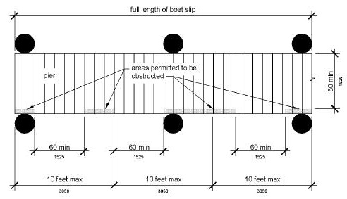
Figure 1003.3.1 Boat Slip Clearance
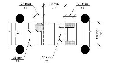
Figure 1003.3.1 (Exception 1) Clear Pier Space Reduction at Boat Slips
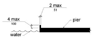
Figure 1003.3.1 (Exception 2) Edge Protection at Boat Slips
1003.3.2 Boarding Pier Clearances.
Boarding piers at boat launch ramps shall provide clear pier space 60 inches (1525 mm) wide minimum and shall extend the full length of the boarding pier. Every 10 feet (3050 mm) maximum of linear pier edge shall contain at least one continuous clear opening 60 inches (1525 mm) wide minimum.
EXCEPTIONS: 1. The clear pier space shall be permitted to be 36 inches (915 mm) wide minimum for a length of 24 inches (610 mm) maximum provided that multiple 36 inch (915 mm) wide segments are separated by segments that are 60 inches (1525 mm) wide minimum and 60 inches (1525 mm) long minimum.
2. Edge protection shall be permitted at the continuous clear openings provided that it is 4 inches (100 mm) high maximum and 2 inches (51 mm) wide maximum.
Advisory 1003.3.2 Boarding Pier Clearances. These requirements do not establish a minimum length for accessible boarding piers at boat launch ramps. The accessible boarding pier should have a length at least equal to that of other boarding piers provided at the facility. If no other boarding pier is provided, the pier would have a length equal to what would have been provided if no access requirements applied. The entire length of accessible boarding piers would be required to comply with the same technical provisions that apply to accessible boat slips. For example, at a launch ramp, if a 20 foot (6100 mm) long accessible boarding pier is provided, the entire 20 feet (6100 mm) must comply with the pier clearance requirements in 1003.3. Likewise, if a 60 foot (18 m) long accessible boarding pier is provided, the pier clearance requirements in 1003.3 would apply to the entire 60 feet (18 m).
The following example applies to a boat launch ramp boarding pier: A chain of floats is provided on a launch ramp to be used as a boarding pier which is required to be accessible by 1003.3.2. At high water, the entire chain is floating and a transition plate connects the first float to the surface of the launch ramp. As the water level decreases, segments of the chain end up resting on the launch ramp surface, matching the slope of the launch ramp.
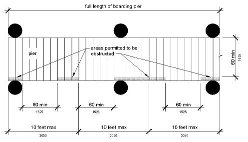
Figure 1003.3.2 Boarding Pier Clearance
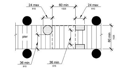
Figure 1003.3.2 (Exception 1) Clear Pier Space Reduction at Boarding Piers
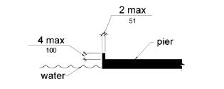
Figure 1003.3.2 (Exception 2) Edge Protection at Boarding Piers
1004.1 Clear Floor Space.
Exercise machines and equipment shall have a clear floor space complying with 305 positioned for transfer or for use by an individual seated in a wheelchair. Clear floor or ground spaces required at exercise machines and equipment shall be permitted to overlap.
1005.1 Accessible Routes.
Accessible routes serving fishing piers and platforms, including gangways and floating piers, shall comply with Chapter 4.
EXCEPTIONS: 1. Accessible routes serving floating fishing piers and platforms shall be permitted to use Exceptions 1, 2, 5, 6, 7 and 8 in 1003.2.1.
2. Where the total length of the gangway or series of gangways serving as part of a required accessible route is 30 feet (9145 mm) minimum, gangways shall not be required to comply with 405.2.
1005.2 Railings.
Where provided, railings, guards, or handrails shall comply with 1005.2.
1005.2.1 Height.
At least 25 percent of the railings, guards, or handrails shall be 34 inches (865 mm) maximum above the ground or deck surface.
EXCEPTION: Where a guard complying with sections 1003.2.12.1 and 1003.2.12.2 of the International Building Code (2000 edition) or sections 1012.2 and 1012.3 of the International Building Code (2003 edition) (incorporated by reference, see "Referenced Standards" in Chapter 1) is provided, the guard shall not be required to comply with 1005.2.1.
1005.2.1.1 Dispersion.
Railings, guards, or handrails required to comply with 1005.2.1 shall be dispersed throughout the fishing pier or platform.
1005.3 Edge Protection.
Where railings, guards, or handrails complying with 1005.2 are provided, edge protection complying with 1005.3.1 or 1005.3.2 shall be provided.
1005.3.1 Curb or Barrier.
Curbs or barriers shall extend 2 inches (51 mm) minimum above the surface of the fishing pier or platform.
1005.3.2 Extended Ground or Deck Surface.
The ground or deck surface shall extend 12 inches (305 mm) minimum beyond the inside face of the railing. Toe clearance shall be provided and shall be 30 inches (760 mm) wide minimum and 9 inches (230 mm) minimum above the ground or deck surface beyond the railing.
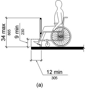
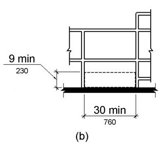
Figure 1005.3.2 Extended Ground or Deck Surface at Fishing Piers and Platforms
1005.4 Clear Floor or Ground Space.
At each location where there are railings, guards, or handrails complying with 1005.2.1, a clear floor or ground space complying with 305 shall be provided. Where there are no railings, guards, or handrails, at least one clear floor or ground space complying with 305 shall be provided on the fishing pier or platform.
1005.5 Turning Space.
At least one turning space complying with 304.3 shall be provided on fishing piers and platforms.
1006.1 General.
Golf facilities shall comply with 1006.
1006.2 Accessible Routes.
Accessible routes serving teeing grounds, practice teeing grounds, putting greens, practice putting greens, teeing stations at driving ranges, course weather shelters, golf car rental areas, bag drop areas, and course toilet rooms shall comply with Chapter 4 and shall be 48 inches (1220 mm) wide minimum. Where handrails are provided, accessible routes shall be 60 inches (1525 mm) wide minimum.
EXCEPTION: Handrails shall not be required on golf courses. Where handrails are provided on golf courses, the handrails shall not be required to comply with 505.
Advisory 1006.2 Accessible Routes. The 48 inch (1220 mm) minimum width for the accessible route is necessary to ensure passage of a golf car on either the accessible route or the golf car passage. This is important where the accessible route is used to connect the golf car rental area, bag drop areas, practice putting greens, practice teeing grounds, course toilet rooms, and course weather shelters. These are areas outside the boundary of the golf course, but are areas where an individual using an adapted golf car may travel. A golf car passage may not be substituted for other accessible routes to be located outside the boundary of the course. For example, an accessible route connecting an accessible parking space to the entrance of a golf course clubhouse is not covered by this provision.
Providing a golf car passage will permit a person that uses a golf car to practice driving a golf ball from the same position and stance used when playing the game. Additionally, the space required for a person using a golf car to enter and maneuver within the teeing stations required to be accessible should be considered.
1006.3 Golf car Passages.
Golf car passages shall comply with 1006.3.
1006.3.1 Clear Width.
The clear width of golf car passages shall be 48 inches (1220 mm) minimum.
1006.3.2 Barriers.
Where curbs or other constructed barriers prevent golf cars from entering a fairway, openings 60 inches (1525 mm) wide minimum shall be provided at intervals not to exceed 75 yards (69 m).
1006.4 Weather Shelters.
A clear floor or ground space 60 inches (1525 mm) minimum by 96 inches (2440 mm) minimum shall be provided within weather shelters.
1007.1 General.
Miniature golf facilities shall comply with 1007.
1007.2 Accessible Routes.
Accessible routes serving holes on miniature golf courses shall comply with Chapter 4. Accessible routes located on playing surfaces of miniature golf holes shall be permitted to use the exceptions in 1007.2.
EXCEPTIONS: 1. Playing surfaces shall not be required to comply with 302.2.
2. Where accessible routes intersect playing surfaces of holes, a 1 inch (25 mm) maximum curb shall be permitted for a width of 32 inches (815 mm) minimum.
3. A slope not steeper than 1:4 for a 4 inch (100 mm) maximum rise shall be permitted.
4. Ramp landing slopes specified by 405.7.1 shall be permitted to be 1:20 maximum.
5. Ramp landing length specified by 405.7.3 shall be permitted to be 48 inches (1220 mm) long minimum.
6. Ramp landing size specified by 405.7.4 shall be permitted to be 48 inches (1220 mm) minimum by 60 inches (1525 mm) minimum.
7. Handrails shall not be required on holes. Where handrails are provided on holes, the handrails shall not be required to comply with 505.
1007.3 Miniature Golf Holes.
Miniature golf holes shall comply with 1007.3.
1007.3.1 Start of Play.
A clear floor or ground space 48 inches (1220 mm) minimum by 60 inches (1525 mm) minimum with slopes not steeper than 1:48 shall be provided at the start of play.
1007.3.2 Golf Club Reach Range Area.
All areas within holes where golf balls rest shall be within 36 inches (915 mm) maximum of a clear floor or ground space 36 inches (915 mm) wide minimum and 48 inches (1220 mm) long minimum having a running slope not steeper than 1:20. The clear floor or ground space shall be served by an accessible route.
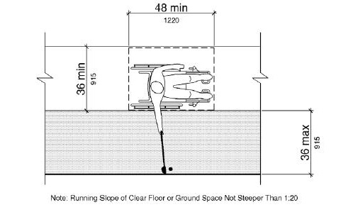
Figure 1007.3.2 Golf Club Reach Range Area
1008.1 General.
Play areas shall comply with 1008.
1008.2 Accessible Routes.
Accessible routes serving play areas shall comply with Chapter 4 and 1008.2 and shall be permitted to use the exceptions in 1008.2.1 through 1008.2.3. Where accessible routes serve ground level play components, the vertical clearance shall be 80 inches high (2030 mm) minimum.
1008.2.1 Ground Level and Elevated Play Components.
Accessible routes serving ground level play components and elevated play components shall be permitted to use the exceptions in 1008.2.1.
EXCEPTIONS: 1. Transfer systems complying with 1008.3 shall be permitted to connect elevated play components except where 20 or more elevated play components are provided no more than 25 percent of the elevated play components shall be permitted to be connected by transfer systems.
2. Where transfer systems are provided, an elevated play component shall be permitted to connect to another elevated play component as part of an accessible route.
1008.2.2 Soft Contained Play Structures.
Accessible routes serving soft contained play structures shall be permitted to use the exception in 1008.2.2.
EXCEPTION: Transfer systems complying with 1008.3 shall be permitted to be used as part of an accessible route.
1008.2.3 Water Play Components.
Accessible routes serving water play components shall be permitted to use the exceptions in 1008.2.3.
EXCEPTIONS: 1. Where the surface of the accessible route, clear floor or ground spaces, or turning spaces serving water play components is submerged, compliance with 302, 403.3, 405.2, 405.3, and 1008.2.6 shall not be required.
2. Transfer systems complying with 1008.3 shall be permitted to connect elevated play components in water.
1008.2.4 Clear Width.
Accessible routes connecting play components shall provide a clear width complying with 1008.2.4.
1008.2.4.1 Ground Level.
At ground level, the clear width of accessible routes shall be 60 inches (1525 mm) minimum.
EXCEPTIONS: 1. In play areas less than 1000 square feet (93 m2), the clear width of accessible routes shall be permitted to be 44 inches (1120 mm) minimum, if at least one turning space complying with 304.3 is provided where the restricted accessible route exceeds 30 feet (9145 mm) in length.
2. The clear width of accessible routes shall be permitted to be 36 inches (915 mm) minimum for a distance of 60 inches (1525 mm) maximum provided that multiple reduced width segments are separated by segments that are 60 inches (1525 mm) wide minimum and 60 inches (1525 mm) long minimum.
1008.2.4.2 Elevated.
The clear width of accessible routes connecting elevated play components shall be 36 inches (915 mm) minimum.
EXCEPTIONS: 1. The clear width of accessible routes connecting elevated play components shall be permitted to be reduced to 32 inches (815 mm) minimum for a distance of 24 inches (610 mm) maximum provided that reduced width segments are separated by segments that are 48 inches (1220 mm) long minimum and 36 inches (915 mm) wide minimum.
2. The clear width of transfer systems connecting elevated play components shall be permitted to be 24 inches (610 mm) minimum.
1008.2.5 Ramps.
Within play areas, ramps connecting ground level play components and ramps connecting elevated play components shall comply with 1008.2.5.
1008.2.5.1 Ground Level.
Ramp runs connecting ground level play components shall have a running slope not steeper than 1:16.
1008.2.5.2 Elevated.
The rise for any ramp run connecting elevated play components shall be 12 inches (305 mm) maximum.
1008.2.5.3 Handrails.
Where required on ramps serving play components, the handrails shall comply with 505 except as modified by 1008.2.5.3.
EXCEPTIONS: 1. Handrails shall not be required on ramps located within ground level use zones.
2. Handrail extensions shall not be required.
1008.2.5.3.1 Handrail Gripping Surfaces.
Handrail gripping surfaces with a circular cross section shall have an outside diameter of 0.95 inch (24 mm) minimum and 1.55 inches (39 mm) maximum. Where the shape of the gripping surface is non-circular, the handrail shall provide an equivalent gripping surface.
The top of handrail gripping surfaces shall be 20 inches (510 mm) minimum and 28 inches (710 mm) maximum above the ramp surface.
1008.2.6 Ground Surfaces.
Ground surfaces on accessible routes, clear floor or ground spaces, and turning spaces shall comply with 1008.2.6.
1008.2.6.1 Accessibility.
Ground surfaces shall comply with ASTM F 1951 (incorporated by reference, see "Referenced Standards" in Chapter 1). Ground surfaces shall be inspected and maintained regularly and frequently to ensure continued compliance with ASTM F 1951.
1008.2.6.2 Use Zones.
Ground surfaces located within use zones shall comply with ASTM F 1292 (1999 edition or 2004 edition) (incorporated by reference, see "Referenced Standards" in Chapter 1).
1008.3 Transfer Systems.
Where transfer systems are provided to connect to elevated play components, transfer systems shall comply with 1008.3.
1008.3.1 Transfer Platforms.
Transfer platforms shall be provided where transfer is intended from wheelchairs or other mobility aids. Transfer platforms shall comply with 1008.3.1.
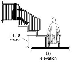
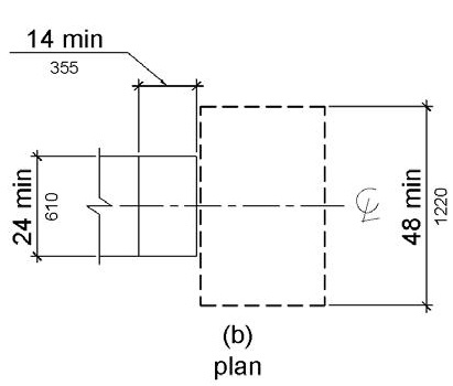
Figure 1008.3.1 Transfer Platforms
1008.3.1.1 Size.
Transfer platforms shall have level surfaces 14 inches (355 mm) deep minimum and 24 inches (610 mm) wide minimum.
1008.3.1.2 Height.
The height of transfer platforms shall be 11 inches (280 mm) minimum and 18 inches (455 mm) maximum measured to the top of the surface from the ground or floor surface.
1008.3.1.3 Transfer Space.
A transfer space complying with 305.2 and 305.3 shall be provided adjacent to the transfer platform. The 48 inch (1220 mm) long minimum dimension of the transfer space shall be centered on and parallel to the 24 inch (610 mm) long minimum side of the transfer platform. The side of the transfer platform serving the transfer space shall be unobstructed.
1008.3.1.4 Transfer Supports.
At least one means of support for transferring shall be provided.
1008.3.2 Transfer Steps.
Transfer steps shall be provided where movement is intended from transfer platforms to levels with elevated play components required to be on accessible routes. Transfer steps shall comply with 1008.3.2.
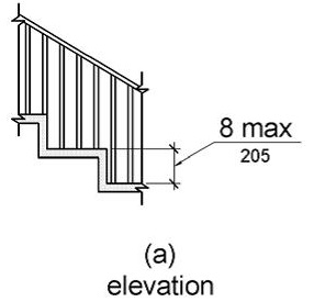
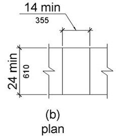
Figure 1008.3.2 Transfer Steps
1008.3.2.1 Size.
Transfer steps shall have level surfaces 14 inches (355 mm) deep minimum and 24 inches (610 mm) wide minimum.
1008.3.2.2 Height.
Each transfer step shall be 8 inches (205 mm) high maximum.
1008.3.2.3 Transfer Supports.
At least one means of support for transferring shall be provided.
1008.4 Play Components.
Ground level play components on accessible routes and elevated play components connected by ramps shall comply with 1008.4.
1008.4.1 Turning Space.
At least one turning space complying with 304 shall be provided on the same level as play components. Where swings are provided, the turning space shall be located immediately adjacent to the swing.
1008.4.2 Clear Floor or Ground Space.
Clear floor or ground space complying with 305.2 and 305.3 shall be provided at play components.
Advisory 1008.4.2 Clear Floor or Ground Space. Clear floor or ground spaces, turning spaces, and accessible routes are permitted to overlap within play areas. A specific location has not been designated for the clear floor or ground spaces or turning spaces, except swings, because each play component may require that the spaces be placed in a unique location. Where play components include a seat or entry point, designs that provide for an unobstructed transfer from a wheelchair or other mobility device are recommended. This will enhance the ability of children with disabilities to independently use the play component.
When designing play components with manipulative or interactive features, consider appropriate reach ranges for children seated in wheelchairs. The following table provides guidance on reach ranges for children seated in wheelchairs. These dimensions apply to either forward or side reaches. The reach ranges are appropriate for use with those play components that children seated in wheelchairs may access and reach. Where transfer systems provide access to elevated play components, the reach ranges are not appropriate.
| Children's Reach Ranges | |||
| Forward or Side Reach | Ages 3 and 4 | Ages 5 through 8 | Ages 9 through 12 |
|
High (maximum) |
36 in (915 mm) | 40 in (1015 mm) | 44 in (1120 mm) |
| Low (minimum) | 20 in (510 mm) | 18 in (455 mm) | 16 in (405 mm) |
1008.4.3 Play Tables.
Where play tables are provided, knee clearance 24 inches (610 mm) high minimum, 17 inches deep (430 mm) minimum, and 30 inches (760 mm) wide minimum shall be provided. The tops of rims, curbs, or other obstructions shall be 31 inches (785 mm) high maximum.
EXCEPTION: Play tables designed and constructed primarily for children 5 years and younger shall not be required to provide knee clearance where the clear floor or ground space required by 1008.4.2 is arranged for a parallel approach.
1008.4.4 Entry Points and Seats.
Where play components require transfer to entry points or seats, the entry points or seats shall be 11 inches (280 mm) minimum and 24 inches (610 mm) maximum from the clear floor or ground space.
EXCEPTION: Entry points of slides shall not be required to comply with 1008.4.4.
1008.4.5 Transfer Supports.
Where play components require transfer to entry points or seats, at least one means of support for transferring shall be provided.
1009.1 General.
Where provided, pool lifts, sloped entries, transfer walls, transfer systems, and pool stairs shall comply with 1009.
1009.2 Pool Lifts.
Pool lifts shall comply with 1009.2.
1009.2.1 Pool Lift Location.
Pool lifts shall be located where the water level does not exceed 48 inches (1220 mm).
EXCEPTIONS: 1. Where the entire pool depth is greater than 48 inches (1220 mm), compliance with 1009.2.1 shall not be required.
2. Where multiple pool lift locations are provided, no more than one pool lift shall be required to be located in an area where the water level is 48 inches (1220 mm) maximum.
1009.2.2 Seat Location.
In the raised position, the centerline of the seat shall be located over the deck and 16 inches (405 mm) minimum from the edge of the pool. The deck surface between the centerline of the seat and the pool edge shall have a slope not steeper than 1:48.
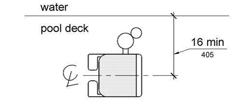
Figure 1009.2.2 Pool Lift Seat Location
1009.2.3 Clear Deck Space.
On the side of the seat opposite the water, a clear deck space shall be provided parallel with the seat. The space shall be 36 inches (915 mm) wide minimum and shall extend forward 48 inches (1220 mm) minimum from a line located 12 inches (305 mm) behind the rear edge of the seat. The clear deck space shall have a slope not steeper than 1:48.
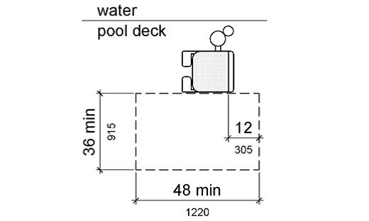
Figure 1009.2.3 Clear Deck Space at Pool Lifts
1009.2.4 Seat Height.
The height of the lift seat shall be designed to allow a stop at 16 inches (405 mm) minimum to 19 inches (485 mm) maximum measured from the deck to the top of the seat surface when in the raised (load) position.
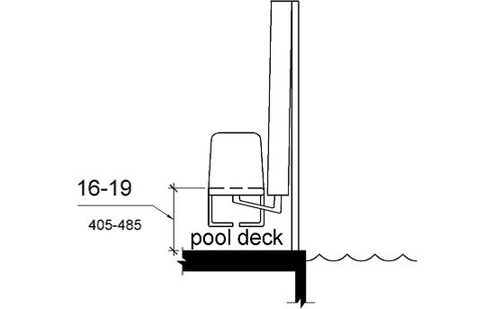
Figure 1009.2.4 Pool Lift Seat Height
1009.2.5 Seat Width.
The seat shall be 16 inches (405 mm) wide minimum.
1009.2.6 Footrests and Armrests.
Footrests shall be provided and shall move with the seat. If provided, the armrest positioned opposite the water shall be removable or shall fold clear of the seat when the seat is in the raised (load) position.
EXCEPTION: Footrests shall not be required on pool lifts provided in spas.
1009.2.7 Operation.
The lift shall be capable of unassisted operation from both the deck and water levels. Controls and operating mechanisms shall be unobstructed when the lift is in use and shall comply with 309.4.
1009.2.8 Submerged Depth.
The lift shall be designed so that the seat will submerge to a water depth of 18 inches (455 mm) minimum below the stationary water level.
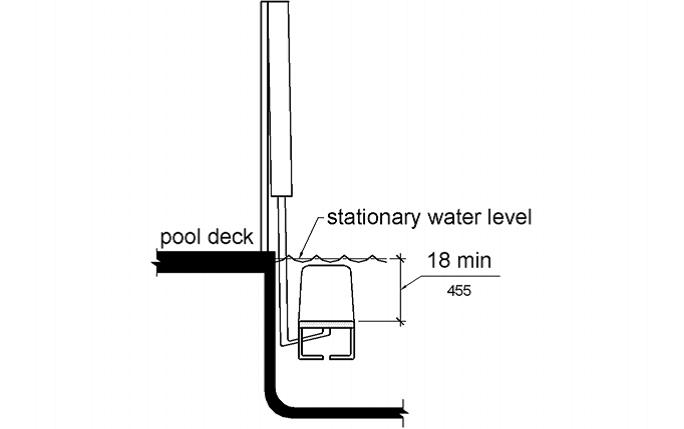
Figure 1009.2.8 Pool Lift Submerged Depth
1009.2.9 Lifting Capacity.
Single person pool lifts shall have a weight capacity of 300 pounds. (136 kg) minimum and be capable of sustaining a static load of at least one and a half times the rated load.
1009.3 Sloped Entries.
Sloped entries shall comply with 1009.3.
1009.3.1 Sloped Entries.
Sloped entries shall comply with Chapter 4 except as modified in 1009.3.1 through 1009.3.3.
EXCEPTION: Where sloped entries are provided, the surfaces shall not be required to be slip resistant.
1009.3.2 Submerged Depth.
Sloped entries shall extend to a depth of 24 inches (610 mm) minimum and 30 inches (760 mm) maximum below the stationary water level. Where landings are required by 405.7, at least one landing shall be located 24 inches (610 mm) minimum and 30 inches (760 mm) maximum below the stationary water level.
EXCEPTION: In wading pools, the sloped entry and landings, if provided, shall extend to the deepest part of the wading pool.
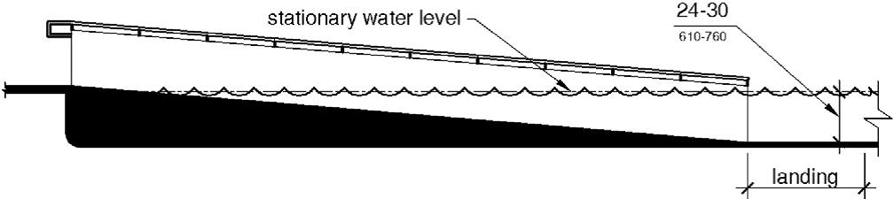
Figure 1009.3.2 Sloped Entry Submerged Depth
1009.3.3 Handrails.
At least two handrails complying with 505 shall be provided on the sloped entry. The clear width between required handrails shall be 33 inches (840 mm) minimum and 38 inches (965 mm) maximum.
EXCEPTIONS: 1. Handrail extensions specified by 505.10.1 shall not be required at the bottom landing serving a sloped entry.
2. Where a sloped entry is provided for wave action pools, leisure rivers, sand bottom pools, and other pools where user access is limited to one area, the handrails shall not be required to comply with the clear width requirements of 1009.3.3.
3. Sloped entries in wading pools shall not be required to provide handrails complying with 1009.3.3. If provided, handrails on sloped entries in wading pools shall not be required to comply with 505.
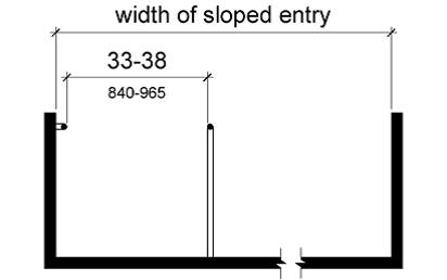
Figure 1009.3.3 Handrails for Sloped Entry
1009.4 Transfer Walls.
Transfer walls shall comply with 1009.4.
1009.4.1 Clear Deck Space.
A clear deck space of 60 inches (1525 mm) minimum by 60 inches (1525 mm) minimum with a slope not steeper than 1:48 shall be provided at the base of the transfer wall. Where one grab bar is provided, the clear deck space shall be centered on the grab bar. Where two grab bars are provided, the clear deck space shall be centered on the clearance between the grab bars.
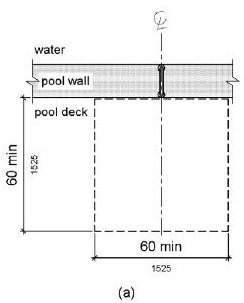
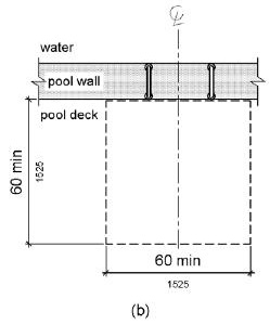
Figure 1009.4.1 Clear Deck Space at Transfer Walls
1009.4.2 Height.
The height of the transfer wall shall be 16 inches (405 mm) minimum and 19 inches (485 mm) maximum measured from the deck.
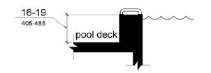
Figure 1009.4.2 Transfer Wall Height
1009.4.3 Wall Depth and Length.
The depth of the transfer wall shall be 12 inches (305 mm) minimum and 16 inches (405 mm) maximum. The length of the transfer wall shall be 60 inches (1525 mm) minimum and shall be centered on the clear deck space.
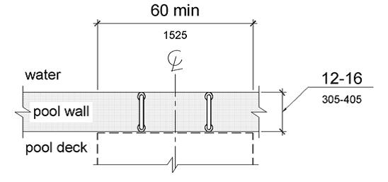
Figure 1009.4.3 Depth and Length of Transfer Walls
1009.4.4 Surface.
Surfaces of transfer walls shall not be sharp and shall have rounded edges.
1009.4.5 Grab Bars.
At least one grab bar complying with 609 shall be provided on the transfer wall. Grab bars shall be perpendicular to the pool wall and shall extend the full depth of the transfer wall. The top of the gripping surface shall be 4 inches (100 mm) minimum and 6 inches (150 mm) maximum above transfer walls. Where one grab bar is provided, clearance shall be 24 inches (610 mm) minimum on both sides of the grab bar. Where two grab bars are provided, clearance between grab bars shall be 24 inches (610 mm) minimum.
EXCEPTION: Grab bars on transfer walls shall not be required to comply with 609.4.
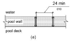
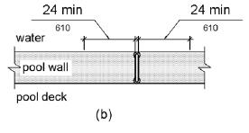
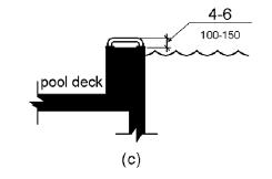
Figure 1009.4.5 Grab Bars for Transfer Walls
1009.5 Transfer Systems.
Transfer systems shall comply with 1009.5.
1009.5.1 Transfer Platform.
A transfer platform shall be provided at the head of each transfer system. Transfer platforms shall provide 19 inches (485 mm) minimum clear depth and 24 inches (610 mm) minimum clear width.
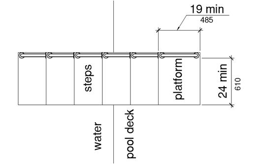
Figure 1009.5.1 Size of Transfer Platform
1009.5.2 Transfer Space.
A transfer space of 60 inches (1525 mm) minimum by 60 inches (1525 mm) minimum with a slope not steeper than 1:48 shall be provided at the base of the transfer platform surface and shall be centered along a 24 inch (610 mm) minimum side of the transfer platform. The side of the transfer platform serving the transfer space shall be unobstructed.
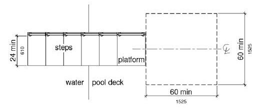
Figure 1009.5.2 Clear Deck Space at Transfer Platform
1009.5.3 Height.
The height of the transfer platform shall comply with 1009.4.2.
1009.5.4 Transfer Steps.
Transfer step height shall be 8 inches (205 mm) maximum. The surface of the bottom tread shall extend to a water depth of 18 inches (455 mm) minimum below the stationary water level.
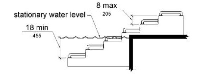
Figure 1009.5.4 Transfer Steps
1009.5.5 Surface.
The surface of the transfer system shall not be sharp and shall have rounded edges.
1009.5.6 Size.
Each transfer step shall have a tread clear depth of 14 inches (355 mm) minimum and 17 inches (430 mm) maximum and shall have a tread clear width of 24 inches (610 mm) minimum.
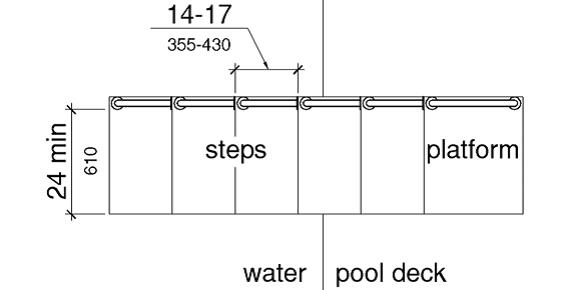
Figure 1009.5.6 Size of Transfer Steps
1009.5.7 Grab Bars.
At least one grab bar on each transfer step and the transfer platform or a continuous grab bar serving each transfer step and the transfer platform shall be provided. Where a grab bar is provided on each step, the tops of gripping surfaces shall be 4 inches (100 mm) minimum and 6 inches (150 mm) maximum above each step and transfer platform. Where a continuous grab bar is provided, the top of the gripping surface shall be 4 inches (100 mm) minimum and 6 inches (150 mm) maximum above the step nosing and transfer platform. Grab bars shall comply with 609 and be located on at least one side of the transfer system. The grab bar located at the transfer platform shall not obstruct transfer.
EXCEPTION: Grab bars on transfer systems shall not be required to comply with 609.4.
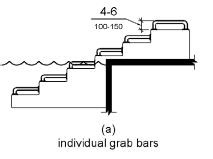
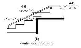
Figure 1009.5.7 Grab Bars
1009.6 Pool Stairs.
Pool stairs shall comply with 1009.6.
1009.6.1 Pool Stairs.
Pool stairs shall comply with 504.
EXCEPTION: Pool step riser heights shall not be required to be 4 inches (100 mm) high minimum and 7 inches (180 mm) high maximum provided that riser heights are uniform.
1009.6.2 Handrails.
The width between handrails shall be 20 inches (510 mm) minimum and 24 inches (610 mm) maximum. Handrail extensions required by 505.10.3 shall not be required on pool stairs.
1010.1 Turning Space.
A circular turning space 60 inches (1525 mm) diameter minimum with slopes not steeper than 1:48 shall be provided at shooting facilities with firing positions.
1011.1 General.
All outdoor constructed features shall comply with 1011.2 and 1011.3. Outdoor constructed features specified in 1011.4 through 1011.8 shall comply with those provisions, as applicable.
1011.2 Clear Ground Space.
A clear ground space complying with 1011.2 shall be provided at outdoor constructed features.
EXCEPTIONS: 1. Where individual outdoor constructed features are altered and the ground surface is not altered, the clear ground space shall not be required to comply with 1011.2.2 and 1011.2.3.
2. In alterations, when an entity determines that a condition in 1019 does not permit full compliance with a specific provision in 1011.2, the clear ground space shall comply with the provision to the extent practicable.
1011.2.1 Size and Location.
The size and location of the clear ground space shall be in accordance with Table 1011.2.1. Unless otherwise specified in Table 1011.2.1, one full unobstructed side of the clear ground space shall adjoin or overlap an outdoor recreation access route or a trail, as applicable, or another clear ground space.
|
Outdoor Constructed Feature |
Minimum Size and Location |
|---|---|
|
Picnic tables |
36 inches (915 mm) on all usable sides of the table measured from the back edge of the benches |
|
Fire rings, grills, fireplaces, and woodstoves |
48 inches (1220 mm) by 48 inches (1220 mm) on all usable sides of the fire ring, grill, fireplace, and woodstove
Center the space on each usable side of the grill, fireplace, and woodstove |
|
Trash and recycling receptacles |
36 inches (915 mm) by 48 inches (1220 mm) positioned for forward approach to the receptacle opening; or 30 inches (760 mm) by 60 inches (1525 mm) positioned for a parallel approach to the receptacle opening |
|
Water hydrants |
72 inches (1830 mm) by 48 inches (1220 mm) with the long side of the space adjoining or overlapping an outdoor recreation access route or trail, as applicable, or another clear ground space
Locate the space so that the water spout is 11 inches (280 mm) minimum and 12 inches (305 mm) maximum from the rear center of the long side of the space |
|
Utility and sewage hookups |
30 inches (760 mm) by 60 inches (1525 mm) with the long side of the space adjoining or overlapping an accessible parking space or pull-up space for recreational vehicles
Locate the space so that the hook-ups are at the rear center of the space
Bollards or other barriers shall not obstruct the clear ground space in front of the hook-ups |
|
Outdoor rinsing showers |
60 inches (1525 mm) by 60 inches (1525 mm) centered on the shower heads
Locate the space so that the shower pedestal or wall with the shower head are at the rear end of the space |
|
Benches |
36 inches (915 mm) by 48 inches (1220 mm) positioned near the bench with one side of the space adjoining an outdoor recreation access route or trail, as applicable
The clear ground space shall not overlap the outdoor recreation access route or trail, or another clear ground space |
|
Viewing Scopes |
36 inches (915 mm) by 48 inches (1220 mm) positioned for forward approach to the viewing scope
Provide knee and toe clearance complying with 306 under the viewing scope
Locate the space so that the eyepiece is centered on the space |
1011.2.2 Surface.
The surface of the clear ground space shall be firm and stable.
1011.2.3 Slope.
The slope of the clear ground space surface shall not be steeper than 1:48 in any direction.
EXCEPTION: Where the surface is other than asphalt, concrete, or boards, slopes not steeper than 1:20 shall be permitted when necessary for drainage.
1011.2.4 Openings.
Openings in the clear ground space surface shall not allow the passage of a sphere more than 1/2 inch (13 mm) in diameter.
1011.3 Operable Parts.
Operable parts shall comply with 309.3 and 309.4.
EXCEPTIONS: 1. Fire rings, grills, fireplaces, wood stoves, water hydrants, and water utility hookups shall comply with 309.4 to the extent practicable.
2. Trash and recycling receptacles with hinged lids and controls to keep out large animals shall comply with 309.4 to the extent practicable.
3. Dumpster type trash and recycling receptacles shall not be required to comply with 309.3 and 309.4.
4. Sewage hatches shall not be required to comply with 309.3 and 309.4.
1011.4 Picnic Tables.
Picnic tables shall comply with 1011.4.
1011.4.1 Height.
The tops of picnic tables shall comply with 902.3.
1011.4.2 Wheelchair Space.
Picnic tables shall provide at least one wheelchair space for each 24 linear feet (7320 mm) of usable table surface perimeter. Wheelchair spaces shall be 30 inches (760 mm) minimum by 48 inches (1220 mm) minimum. Wheelchair spaces shall be positioned for a forward approach to the table and provide knee and toe clearance complying with 306 under the table.
1011.5 Fire Rings, Grills, Fireplaces, and Wood Stoves.
Fire rings, grills, fireplaces, and wood stoves shall comply with 1011.5.
1011.5.1 Fire Building Surfaces.
Fire building surfaces shall be 9 inches (230 mm) minimum above the ground.
1011.5.2 Cooking Surfaces.
Where provided, cooking surfaces shall be 15 inches (380 mm) minimum and 34 inches (865 mm) maximum above the ground.
1011.5.3 Raised Edges or Walls.
Where fire rings, grills, or fireplaces are constructed with raised edges or walls, the depth of the raised edge or wall shall be 10 inches (255 mm) maximum.
1011.6 Water Spouts.
Water spouts at water hydrants and water utility hook-ups shall be 28 inches (710 mm) minimum and 36 inches (915 mm) maximum above the ground.
1011.7 Outdoor Rinsing Showers.
Outdoor rinsing showers shall provide at least one hand-held shower spray unit with a hose 59 inches (1500 mm) long minimum. The hand-held shower spray unit shall have at least one fixed position located 15 inches minimum (380 mm) and 48 inches (1220 mm) maximum above the ground.
EXCEPTION: Where vandalism is a consideration, a fixed shower head located at 48 inches (1220 mm) above the ground shall be permitted in place of a hand-held shower spray unit.
1011.8 Viewing Scopes.
Eyepieces on viewing scopes shall be 43 inches (1090 mm) minimum and 51 inches (1295 mm) maximum above the ground.
1012.1 General.
Parking spaces within camping units and picnic units with mobility features and pull-up spaces for recreational vehicles at dump stations shall comply with 1012.
1012.2 Recreational Vehicles.
Parking spaces and pull-up spaces for recreational vehicles shall be 20 feet (6100 mm) wide minimum.
EXCEPTION: Where two adjacent parking spaces are provided for recreational vehicles, one parking space shall be permitted to be 16 feet (4880 mm) wide minimum.
1012.3 Other Vehicles.
Parking spaces for vehicles, other than recreational vehicles, shall be 16 feet (4880 mm) wide minimum.
EXCEPTION: Where two adjacent parking spaces are provided for vehicles, other than recreational vehicles, one parking space shall be permitted to be 8 feet (2440 mm) wide minimum.
1012.4 Surface.
The surface of parking spaces and pull-up spaces shall be firm and stable.
1012.5 Slope.
The slope of the surface of parking spaces and pull-up spaces shall not be steeper than 1:48 in any direction.
EXCEPTION: Where the surface is other than asphalt, concrete, or boards, slopes not steeper than 1:20 shall be permitted when necessary for drainage.
1013.1 General.
Tent pads and tent platforms shall comply with 1013.
EXCEPTION: When an entity determines that a condition in 1019 does not permit full compliance with a specific provision in 1013, the tent pad and tent platform shall comply with the provision to the extent practicable.
1013.2 Clear Ground Space.
Clear ground space complying with 1013.2 shall be provided on all usable sides of tent pads and tent platforms.
1013.2.1 Size.
The clear ground space shall be 48 inches (1220 mm) wide minimum.
1013.2.2 Surface.
The surface of the clear ground space shall be firm and stable. The surface shall allow use of tent stakes and other tent securement devices.
1013.3 Slope.
The slope of the surface of tent pads, tent platforms, and clear ground spaces shall not be steeper than 1:48 in any direction.
EXCEPTION: Where the surface is other than asphalt, concrete, or boards, slopes not steeper than 1:20 shall be permitted where necessary for drainage.
1013.4 Height.
Tent platforms shall be 19 inches (485 mm) high maximum measured from the clear ground space to the tent platform surface.
1014.1 General.
Camp shelters shall comply with 1014.
EXCEPTIONS: 1. When an entity determines that a condition in 1019 does not permit full compliance with a specific provision in 1014, the camp shelter shall comply with the provision to the extent practicable.
2. Camp shelters shall not be required to comply with 307.
1014.2 Entrance.
Camp shelters shall provide an entrance complying with 1014.2.1 or 1014.2.2.
1014.2.1 Transfer Access.
Where transfer access is provided at the entrance to a camp shelter, the entrance shall comply with 1014.2.1.
1014.2.1.1 Clear Ground Space.
A clear ground space shall be provided at the entrance to the camp shelter. The clear ground space shall be 36 inches (915 mm) minimum by 48 inches (1220 mm) minimum and shall be positioned for a parallel approach to the camp shelter. One full unobstructed side of the clear ground space shall adjoin or overlap an outdoor recreation access route or trail, as applicable, or another clear ground space.
The surface of the clear ground space shall be firm and stable.
The slope of the surface of the clear ground space shall not be steeper than 1:48 in any direction.
EXCEPTION: Where the surface is other than asphalt, concrete, or boards, slopes not steeper than 1:20 shall be permitted where necessary for drainage.
1014.2.1.2 Floor Height.
The camp shelter floor at the entrance shall be 19 inches (485 mm) high maximum measured from the clear ground space.
1014.2.2 Roll-in Access.
Where roll-in access is provided at the entrance to a camp shelter, the entrance shall comply with 1014.2.2.
1014.2.2.1 Level or Sloped Entry Route.
Camp shelters providing roll-in access shall have a level or sloped entry route complying with 1016 or 1017, as applicable.
1014.2.2.2 Turning Space.
A turning space complying with 304.3 shall be provided within the camp shelter.
1014.3 Floor.
The floor within camp shelters shall comply with 1014.3.
1014.3.1 Surface.
The floor surface shall be firm and stable.
1014.3.2 Slope.
The slope of the floor surface shall not be steeper than 1:48 in any direction.
EXCEPTION: Where the floor surface is other than asphalt, concrete, or boards, slopes not steeper than 1:20 shall be permitted when necessary for drainage.
1015.1 General.
Viewing areas shall comply with 1015.
EXCEPTION: In alterations, when an entity determines that a condition in 1019 does not permit full compliance with a specific provision in 1015, the viewing area shall comply with the provision to the extent practicable.
1015.2 Clear Ground Space.
A clear ground space shall be provided at each distinct viewing location. The clear ground space shall be 36 inches (915 mm) minimum by 48 inches (1220 mm) minimum and shall be positioned for either a forward or parallel approach to the viewing location. One full unobstructed side of the clear ground space shall adjoin or overlap an outdoor recreation access route or trail, as applicable, or another clear ground space.
1015.3 Viewing Space.
Each distinct viewing location shall provide a viewing space adjacent to the clear ground space required by 1015.2 through which the point of interest is viewable. The viewing space shall be 32 inches (815 mm) maximum and 51 inches (1295 mm) minimum high above the ground and shall extend the full width of the clear ground space.
EXCEPTION: Guards or similar safety barriers shall be permitted to obstruct the viewing space to the extent the obstruction is necessary for the guard or safety barrier to serve its intended purpose.
1015.4 Turning Space.
A turning space complying with 304.3 shall be provided within viewing areas.
1015.5 Surface.
The surface of clear ground spaces and turning spaces shall be firm and stable.
1015.6 Slope.
The slope of the surface of clear ground spaces and turning spaces shall not be steeper than 1:48 in any direction.
EXCEPTION: Where the surface is other than asphalt, concrete, or boards, slopes not steeper than 1:20 shall be permitted when necessary for drainage.
1016.1 General.
Outdoor recreation access routes shall comply with 1016.
EXCEPTIONS: 1. In alterations to existing camping facilities, picnic facilities, and trailheads, when an entity determines that a condition in 1019 does not permit full compliance with a specific provision in 1016 on a portion of an outdoor recreation access route, the portion of the outdoor recreation access route shall comply with the provision to the extent practicable.
2. At viewing areas, when an entity determines that a condition in 1019 does not permit full compliance on a portion of an outdoor recreation access route with a specific provision in 1016, the portion of the outdoor recreation access route shall comply with the provision to the extent practicable.
3. Where outdoor recreation access routes are provided within vehicular ways, outdoor recreation access routes shall not be required to comply with 1016.4, 1016.7, and 1016.8.
1016.2 Surface.
The surface of outdoor recreation access routes, passing spaces, and resting intervals shall be firm and stable.
1016.3 Clear Width.
The clear width of outdoor recreation access routes shall be 36 inches (915 mm) minimum.
1016.4 Passing Spaces.
Outdoor recreation access routes with a clear width less than 60 inches (1525 mm) shall provide passing spaces complying with 1016.4 at intervals of 200 feet (61 m) maximum. Passing spaces and resting intervals shall be permitted to overlap.
Advisory 1016.4 Passing Spaces. Entities should consider providing either a 60 inches (1525 mm) minimum clear width on outdoor recreation access routes or passing spaces at shorter intervals if the clear width is less than 60 inches (1525 mm), where the route is:
--Heavily used or adjoins elements, space, or facilities that are heavily used; or
--A boardwalk or otherwise not at the same level as the ground surface adjoining the route.
1016.4.1 Size.
The passing space shall be either:
1. A space 60 inches (1525 mm) minimum by 60 inches (1525 mm) minimum; or
2. The intersection of two outdor recreation access routes providing a T-shaped space complying with 304.3.2 where the base and the arms of the T-shaped space extend 48 inches (1220 mm) minimum beyond the intersection. Vertical alignment at the intersection of the outdoor recreation access routes that form the T-shaped space shall be nominally planar.
1016.5 Obstacles.
Obstacles on outdoor recreation access routes, passing spaces, and resting intervals shall not exceed 1/2 inch (13 mm) in height measured vertically to the highest point.
EXCEPTION: Where the surface is other than asphalt, concrete, or boards, obstacles shall be permitted to not exceed 1 inch (25 mm) in height measured vertically to the highest point.
1016.6 Openings.
Openings in the surface of outdoor recreation access routes shall not allow the passage of a sphere more than 1/2 inch (13 mm) in diameter.
1016.7 Slopes.
The slopes of outdoor recreation access routes shall comply with 1016.7.
1016.7.1 Maximum Running Slope and Segment Length.
The running slope of any segment of an outdoor recreation access route shall not be steeper than 1:10 (10%). Where the running slope of a segment of an outdoor recreation access route is steeper than 1:20 (5%), the maximum length of the segment shall be in accordance with Table 1016.7.1, and a resting interval complying with 1016.8 shall be provided at the top and bottom of each segment.
Table 1016.7.1
Maximum Running Slope and Segment Length
|
Running Slope of Outdoor Recreation Access Route Segment |
Maximum Length of Segment |
|
|
Steeper than |
But not Steeper than |
|
|
1:20 (5%) |
1:12 (8.33%) |
50 feet (15 m) |
|
1:12 (8.33%) |
1:10 (10%) |
30 feet (9 m) |
1016.7.2 Cross Slope.
The cross slope shall not be steeper than 1:48.
EXCEPTION: Where the surface is other than concrete, asphalt, or boards, cross slopes not steeper than 1:20 shall be permitted when necessary for drainage.
1016.8 Resting Intervals.
Resting intervals shall comply with 1016.8.
1016.8.1 Length.
The resting interval length shall be 60 inches (1525 mm) long minimum.
1016.8.2 Width.
Where resting intervals are provided within an outdoor recreation access route, resting intervals shall be at least as wide as the widest segment of the outdoor recreation access route leading to the resting interval. Where resting intervals are provided adjacent to an outdoor recreation access route, the resting interval shall be 36 inches (915 mm) wide minimum.
1016.8.3 Slope.
Resting intervals shall have slopes not steeper than 1:48 in any direction.
EXCEPTION: Where the surface is other than concrete, asphalt, or boards, slopes not steeper than 1:20 shall be permitted when necessary for drainage.
1016.8.4 Turning Space.
Where resting intervals are provided adjacent to an outdoor recreation access route, a turning space complying with 304.3.2 shall be provided. Vertical alignment between the outdoor recreation access route, turning space, and resting interval shall be nominally planar.
1016.9 Protruding Objects.
Constructed elements on outdoor recreation access routes, passing spaces, and resting intervals shall comply with 307.
1017.1 General.
Trails shall comply with 1017.
EXCEPTIONS: 1. When an entity determines that a condition in 1019 does not permit full compliance with a specific provision in 1017 on a portion of a trail, the portion of the trail shall comply with the provision to the extent practicable.
2. After applying Exception 1, when an entity determines that it is impracticable for the entire trail to comply with 1017, the trail shall not be required to comply with 1017.
1017.2 Surface.
The surface of trails, passing spaces, and resting intervals shall be firm and stable.
1017.3 Clear Tread Width.
The clear tread width of trails shall be 36 inches (915 mm) minimum.
1017.4 Passing Spaces.
Trails with a clear tread width less than 60 inches (1525 mm) shall provide passing spaces complying with 1017.4 at intervals of 1000 feet (300 m) maximum. Where the full length of a trail does not fully comply with 1017, a passing space shall be located at the end of the trail segment that fully complies with 1017. Passing spaces and resting intervals shall be permitted to overlap.
Advisory 1017.4 Passing Spaces. Entities should consider providing either a 60 inches (1525 mm) minimum clear tread width or passing spaces at shorter intervals if the clear tread width is less than 60 inches (1525 mm), where a trail is:
--Heavily used; or
--A boardwalk or otherwise not at the same level as the ground surface adjoining the trail.
Where the full length of the trail does not fully comply with 1017, locating a passing space at the end of the trail segment that fully complies with 1017 enables a person who uses a mobility device to turn and exit the trail.
1017.4.1 Size.
The passing space shall be either:
1. A space 60 inches (1525 mm) minimum by 60 inches (1525 mm) minimum; or
2. The intersection of two trails providing a T-shaped space complying with 304.3.2 where the base and the arms of the T-shaped space extend 48 inches (1220 mm) minimum beyond the intersection. Vertical alignment at the intersection of the trails that form the T-shaped space shall be nominally planar.
1017.5 Tread Obstacles.
Tread obstacles on trails, passing spaces, and resting intervals shall not exceed 1/2 inch (13 mm) in height measured vertically to the highest point.
EXCEPTION: Where the surface is other than asphalt, concrete, or boards, tread obstacles shall be permitted to not exceed 2 inches (50 mm) in height measured vertically to the highest point.
1017.6 Openings.
Openings in the surface of trails, passing spaces, and resting intervals shall not allow the passage of a sphere more than 1/2 inch (13 mm) in diameter.
1017.7 Slopes.
The slopes of trails shall comply with 1017.7.
1017.7.1 Maximum Running Slope and Segment Length.
Not more than 30 percent of the total length of a trail shall have a running slope steeper than 1:12 (8.33%). The running slope of any segment of a trail shall not be steeper than 1:8 (12%). Where the running slope of a segment of a trail is steeper than 1:20 (5%), the maximum length of the segment shall be in accordance with Table 1017.7.1, and a resting interval complying with 1017.8 shall be provided at the top and bottom of each segment.
Table 1017.7.1
Maximum Running Slope and Segment Length
|
Running Slope of Trail Segment |
Maximum Length of Segment
|
|
|
Steeper than |
But not Steeper than |
|
|
1:20 (5%) |
1:12 (8.33%) |
200 feet (61 m) |
|
1:12 (8.33%) |
1:10 (10%) |
30 feet (9 m) |
|
1.10 (10%) |
1.8 (12%) |
10 feet (3050 mm) |
1017.7.2 Cross Slope.
The cross slope shall not be steeper than 1:48.
EXCEPTION: Where the surface is other than concrete, asphalt, or boards, cross slopes not steeper than 1:20 shall be permitted when necessary for drainage.
1017.8 Resting Intervals.
Resting intervals shall comply with 1017.8.
1017.8.1 Length.
The resting interval length shall be 60 inches (1525 mm) long minimum.
1017.8.2 Width.
Where resting intervals are provided within the trail tread, resting intervals shall be at least as wide as the widest segment of the trail tread leading to the resting interval. Where resting intervals are provided adjacent to the trail tread, the resting interval clear width shall be 36 inches (915 mm) minimum.
1017.8.3 Slope.
Resting intervals shall have slopes not steeper than 1:48 in any direction.
EXCEPTION: Where the surface is other than concrete, asphalt, or boards, cross slopes not steeper than 1:20 shall be permitted when necessary for drainage.
1017.8.4 Turning Space.
Where resting intervals are provided adjacent to the trail tread, a turning space complying with 304.3.2 shall be provided. Vertical alignment between the trail tread, turning space, and resting interval shall be nominally planar.
1017.9 Protruding Objects.
Constructed elements on trails, passing spaces, and resting intervals shall comply with 307.
1017.10 Trailhead Signs.
Trail information signs at trailheads shall include the following:
1. Length of the trail or trail segment;
2. Surface type;
3. Typical and minimum tread width;
4. Typical and maximum running slope; and
5. Typical and maximum cross slope.
1018.1 General.
Beach access routes shall comply with 1018.
EXCEPTIONS: 1. When an entity determines that a condition in 1019 does not permit full compliance with a specific provision in 1018 on a portion of a beach access route, the portion of the beach access route shall comply with the provision to the extent practicable.
2. After applying Exception 1, when an entity determines that it is impracticable to provide a beach access route complying with 1018, a beach access route shall not be required.
3. Removable beach access routes shall not be required to comply with 1018.7, 1018.8, and 1018.10.
1018.2 Connections.
Beach access routes shall connect an entry point to the beach to the:
1. High tide level at tidal beaches;
2. Mean high water level at river beaches; or
3. Normal recreation water level at lake, pond, and reservoir beaches.
1018.3 Surface.
The surface of beach access routes and resting intervals shall be firm and stable.
1018.4 Clear Width.
The clear width of beach access routes shall be 60 inches (1525 mm) minimum.
EXCEPTION: At dune crossings, the clear width of beach access routes that are not removable shall be permitted to be reduced to 48 inches (1220 mm) minimum.
1018.5 Obstacles.
Obstacles on beach access routes and resting intervals shall not exceed 1/2 inch (13 mm) in height measured vertically to the highest point.
EXCEPTION: Where the surface is other than asphalt, concrete, or boards, obstacles shall be permitted to not exceed 1 inch (25 mm) in height measured vertically to the highest point.
1018.6 Openings.
Openings in the surface of beach access routes and resting intervals shall not allow the passage of a sphere more than 1/2 inch (13 mm) in diameter.
1018.7 Slopes.
The slopes of beach access routes shall comply with 1018.7.
1018.7.1 Maximum Running Slope and Segment Length.
The running slope of any segment of a beach access route shall not be steeper than 1:10 (10%). Where the running slope of a segment of a beach access route is steeper than 1:20 (5%), the maximum length of the segment shall be in accordance with Table 1018.7.1, and a resting interval complying with 1018.8 shall be provided at the top and bottom of each segment.
Table 1018.7.1
Maximum Running Slope and Segment Length
|
Running Slope of Beach Access Route Segment |
Maximum Length of Segment |
|
|
Steeper than |
But not Steeper than |
|
|
1:20 (5%) |
1:12 (8.33%) |
50 feet (15 m) |
|
1:12 (8.33%) |
1:10 (10%) |
30 feet (9 m) |
1018.7.2 Cross Slope.
The cross slope shall not be steeper than 1:48.
EXCEPTION: Where the surface is other than concrete, asphalt, or boards, cross slopes not steeper than 1:20 shall be permitted when necessary for drainage.
1018.8 Resting Intervals.
Resting intervals shall comply with 1018.8.
1018.8.1 Size.
Resting intervals shall be 60 inches minimum (1525 mm) by 60 inches (1525 mm) minimum.
1018.8.2 Slope.
Resting intervals shall have a slope not steeper than 1:48 in any direction.
EXCEPTION: Where the surface is other than concrete, asphalt, or boards, cross slopes not steeper than 1:20 shall be permitted when necessary for drainage.
1018.9 Protruding Objects.
Constructed elements on beach access routes and resting intervals shall comply with 307.
1018.10 Dune Crossings.
Where the slope of a beach access route at a dune crossing is steeper than 1:20 (5%), handrails complying with 505 and curbs or barriers shall be provided. The curbs or barriers shall prevent the passage of a 2 inch (50 mm) diameter sphere, where any portion of the sphere is within 2 inches (50 mm) of the crossing surface.
1019.1 General.
Exceptions to specific provisions in 1011, 1013, 1014, 1015, 1016, 1017, and 1018 shall be permitted when an entity determines that any of the following conditions does not permit full compliance with the provision:
1. Compliance is not practicable due to terrain.
2. Compliance cannot be accomplished with the prevailing construction practices.
3. Compliance would fundamentally alter the function or purpose of the facility or the setting.
4. Compliance is limited or precluded by any of the following laws, or by decisions or opinions issued or agreements executed pursuant to any of the following laws:
--Endangered Species Act (16 U.S.C. §§ 1531 et seq.);
--National Environmental Policy Act (42 U.S.C. §§ 4321 et seq.);
--National Historic Preservation Act (16 U.S.C. §§ 470 et seq.);
--Wilderness Act (16 U.S.C. §§ 1131 et seq.); or
--Other federal, state, or local law the purpose of which is to preserve threatened or endangered species; the environment; or archaeological, cultural, historical, or other significant natural features.
Advisory 1019.1 General. Exceptions in the following sections require compliance to the extent practicable when an entity determines that a condition in 1019 does not permit full compliance with a specific provision:
• 1011.2 Exception 2 (clear ground space in alterations to outdoor constructed features);
• 1013.1 Exception (any provision for tent pads and tent platforms);
• 1014.1 Exception 1 (any provision for camp shelters);
• 1015.1 Exception (any provision in alterations to viewing areas);
• 1016.1 Exception 1 (any provision for outdoor recreation access routes in alterations to existing camping facilities, picnic facilities, and trailheads);
• 1016.1 Exception 2 (any provision for outdoor recreation access routes at viewing areas);
• 1017.1 Exception 1 (any provision for trails); and
• 1018.1 Exception 1 (any provision for beach access routes).
Entities should consider all design options before using the exceptions. On outdoor recreation access routes, trails, and beach access routes, the exceptions apply only on the portion of the route where the condition applies. The outdoor recreation access route, trail, or beach access route is required to fully comply with the provisions in 1016, 1017, and 1018, as applicable, at all other portions of the route where the conditions do not apply. There are additional exceptions that apply to an entire trail or beach access route in 1017.1 and 1018.1.
Condition 4 allows the following to be a basis for using the exceptions:
• Opinions issued by the Secretary of the Interior pursuant to the Endangered Species Act stating how a federal agency can implement an action without jeopardizing the continued existence of any endangered species or threatened species, or destroying or adversely modifying the habitat of such species (16 U.S.C. 1536 (b) (3) (A));
• Decisions issued by a federal agency pursuant to the National Environmental Policy Act in actions requiring environmental impact statements stating how it will avoid or minimize environmental harm (42 U.S.C. 4332; 40 CFR 1505.2);
• Agreements executed or decisions issued by a federal agency pursuant to National Historic Preservation Act stating how it will avoid, minimize, or mitigate adverse effects on historical properties (16 U.S.C. 470f and 470h-2; 36 CFR 800.6 (b) (iv) and 800.7 (c) (4)); and
• Provisions in the Wilderness Act that require federal agencies to preserve the wilderness character of designated wilderness areas and prohibit any structure or installation within such areas (16 U.S.C. 1131 (b) and (c)).
Condition 4 also applies where archaeological, cultural, historical, or other significant natural features are eligible for protection under federal, state, or local law.
User Comments/Questions
Add Comment/Question