ABA Accessibility Standard for GSA Facilities Pocket Guide
1009 Swimming Pools, Wading Pools, and Spas
1009.1 General.
Where provided, pool lifts, sloped entries, transfer walls, transfer systems, and pool stairs shall comply with 1009.
1009.2 Pool Lifts.
Pool lifts shall comply with 1009.2.
1009.2.1 Pool Lift Location.
Pool lifts shall be located where the water level does not exceed 48 inches (1220 mm).
EXCEPTIONS: 1. Where the entire pool depth is greater than 48 inches (1220 mm), compliance with 1009.2.1 shall not be required.
2. Where multiple pool lift locations are provided, no more than one pool lift shall be required to be located in an area where the water level is 48 inches (1220 mm) maximum.
1009.2.2 Seat Location.
In the raised position, the centerline of the seat shall be located over the deck and 16 inches (405 mm) minimum from the edge of the pool. The deck surface between the centerline of the seat and the pool edge shall have a slope not steeper than 1:48.
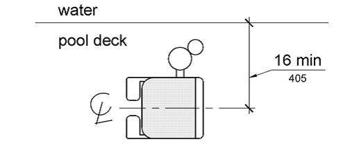
Figure 1009.2.2 Pool Lift Seat Location
1009.2.3 Clear Deck Space.
On the side of the seat opposite the water, a clear deck space shall be provided parallel with the seat. The space shall be 36 inches (915 mm) wide minimum and shall extend forward 48 inches (1220 mm) minimum from a line located 12 inches (305 mm) behind the rear edge of the seat. The clear deck space shall have a slope not steeper than 1:48.
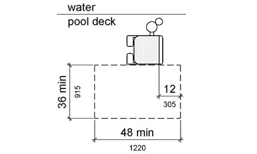
Figure 1009.2.3 Clear Deck Space at Pool Lifts
1009.2.4 Seat Height.
The height of the lift seat shall be designed to allow a stop at 16 inches (405 mm) minimum to 19 inches (485 mm) maximum measured from the deck to the top of the seat surface when in the raised (load) position.
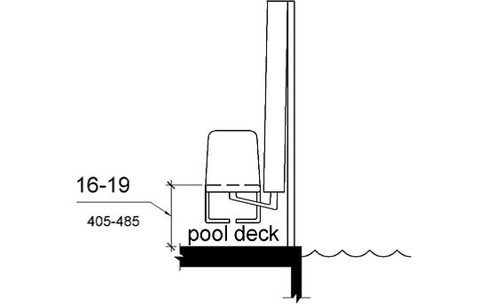
Figure 1009.2.4 Pool Lift Seat Height
1009.2.5 Seat Width.
The seat shall be 16 inches (405 mm) wide minimum.
1009.2.6 Footrests and Armrests.
Footrests shall be provided and shall move with the seat. If provided, the armrest positioned opposite the water shall be removable or shall fold clear of the seat when the seat is in the raised (load) position.
EXCEPTION: Footrests shall not be required on pool lifts provided in spas.
1009.2.7 Operation.
The lift shall be capable of unassisted operation from both the deck and water levels. Controls and operating mechanisms shall be unobstructed when the lift is in use and shall comply with 309.4.
1009.2.8 Submerged Depth.
The lift shall be designed so that the seat will submerge to a water depth of 18 inches (455 mm) minimum below the stationary water level.
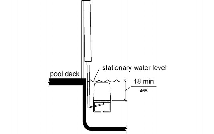
Figure 1009.2.8 Pool Lift Submerged Depth
1009.2.9 Lifting Capacity.
Single person pool lifts shall have a weight capacity of 300 pounds. (136 kg) minimum and be capable of sustaining a static load of at least one and a half times the rated load.
1009.3 Sloped Entries.
Sloped entries shall comply with 1009.3.
1009.3.1 Sloped Entries.
Sloped entries shall comply with Chapter 4 except as modified in 1009.3.1 through 1009.3.3.
EXCEPTION: Where sloped entries are provided, the surfaces shall not be required to be slip resistant.
1009.3.2 Submerged Depth.
Sloped entries shall extend to a depth of 24 inches (610 mm) minimum and 30 inches (760 mm) maximum below the stationary water level. Where landings are required by 405.7, at least one landing shall be located 24 inches (610 mm) minimum and 30 inches (760 mm) maximum below the stationary water level.
EXCEPTION: In wading pools, the sloped entry and landings, if provided, shall extend to the deepest part of the wading pool.
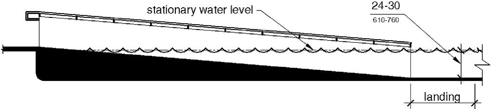
Figure 1009.3.2 Sloped Entry Submerged Depth
1009.3.3 Handrails.
At least two handrails complying with 505 shall be provided on the sloped entry. The clear width between required handrails shall be 33 inches (840 mm) minimum and 38 inches (965 mm) maximum.
EXCEPTIONS: 1. Handrail extensions specified by 505.10.1 shall not be required at the bottom landing serving a sloped entry.
2. Where a sloped entry is provided for wave action pools, leisure rivers, sand bottom pools, and other pools where user access is limited to one area, the handrails shall not be required to comply with the clear width requirements of 1009.3.3.
3. Sloped entries in wading pools shall not be required to provide handrails complying with 1009.3.3. If provided, handrails on sloped entries in wading pools shall not be required to comply with 505.
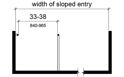
Figure 1009.3.3 Handrails for Sloped Entry
1009.4 Transfer Walls.
Transfer walls shall comply with 1009.4.
1009.4.1 Clear Deck Space.
A clear deck space of 60 inches (1525 mm) minimum by 60 inches (1525 mm) minimum with a slope not steeper than 1:48 shall be provided at the base of the transfer wall. Where one grab bar is provided, the clear deck space shall be centered on the grab bar. Where two grab bars are provided, the clear deck space shall be centered on the clearance between the grab bars.
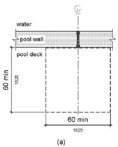
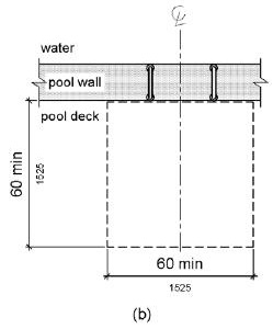
Figure 1009.4.1 Clear Deck Space at Transfer Walls
1009.4.2 Height.
The height of the transfer wall shall be 16 inches (405 mm) minimum and 19 inches (485 mm) maximum measured from the deck.
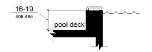
Figure 1009.4.2 Transfer Wall Height
1009.4.3 Wall Depth and Length.
The depth of the transfer wall shall be 12 inches (305 mm) minimum and 16 inches (405 mm) maximum. The length of the transfer wall shall be 60 inches (1525 mm) minimum and shall be centered on the clear deck space.
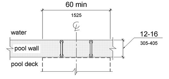
Figure 1009.4.3 Depth and Length of Transfer Walls
1009.4.4 Surface.
Surfaces of transfer walls shall not be sharp and shall have rounded edges.
1009.4.5 Grab Bars.
At least one grab bar complying with 609 shall be provided on the transfer wall. Grab bars shall be perpendicular to the pool wall and shall extend the full depth of the transfer wall. The top of the gripping surface shall be 4 inches (100 mm) minimum and 6 inches (150 mm) maximum above transfer walls. Where one grab bar is provided, clearance shall be 24 inches (610 mm) minimum on both sides of the grab bar. Where two grab bars are provided, clearance between grab bars shall be 24 inches (610 mm) minimum.
EXCEPTION: Grab bars on transfer walls shall not be required to comply with 609.4.
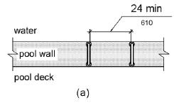
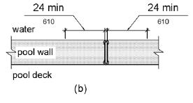
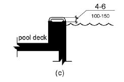
Figure 1009.4.5 Grab Bars for Transfer Walls
1009.5 Transfer Systems.
Transfer systems shall comply with 1009.5.
1009.5.1 Transfer Platform.
A transfer platform shall be provided at the head of each transfer system. Transfer platforms shall provide 19 inches (485 mm) minimum clear depth and 24 inches (610 mm) minimum clear width.
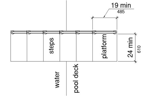
Figure 1009.5.1 Size of Transfer Platform
1009.5.2 Transfer Space.
A transfer space of 60 inches (1525 mm) minimum by 60 inches (1525 mm) minimum with a slope not steeper than 1:48 shall be provided at the base of the transfer platform surface and shall be centered along a 24 inch (610 mm) minimum side of the transfer platform. The side of the transfer platform serving the transfer space shall be unobstructed.
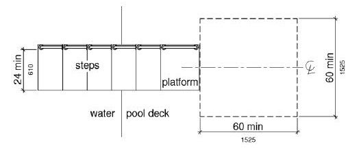
Figure 1009.5.2 Clear Deck Space at Transfer Platform
1009.5.3 Height.
The height of the transfer platform shall comply with 1009.4.2.
1009.5.4 Transfer Steps.
Transfer step height shall be 8 inches (205 mm) maximum. The surface of the bottom tread shall extend to a water depth of 18 inches (455 mm) minimum below the stationary water level.
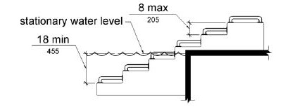
Figure 1009.5.4 Transfer Steps
1009.5.5 Surface.
The surface of the transfer system shall not be sharp and shall have rounded edges.
1009.5.6 Size.
Each transfer step shall have a tread clear depth of 14 inches (355 mm) minimum and 17 inches (430 mm) maximum and shall have a tread clear width of 24 inches (610 mm) minimum.
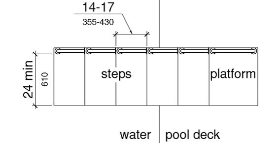
Figure 1009.5.6 Size of Transfer Steps
1009.5.7 Grab Bars.
At least one grab bar on each transfer step and the transfer platform or a continuous grab bar serving each transfer step and the transfer platform shall be provided. Where a grab bar is provided on each step, the tops of gripping surfaces shall be 4 inches (100 mm) minimum and 6 inches (150 mm) maximum above each step and transfer platform. Where a continuous grab bar is provided, the top of the gripping surface shall be 4 inches (100 mm) minimum and 6 inches (150 mm) maximum above the step nosing and transfer platform. Grab bars shall comply with 609 and be located on at least one side of the transfer system. The grab bar located at the transfer platform shall not obstruct transfer.
EXCEPTION: Grab bars on transfer systems shall not be required to comply with 609.4.
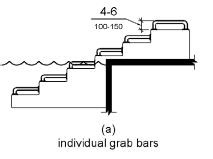
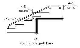
Figure 1009.5.7 Grab Bars
1009.6 Pool Stairs.
Pool stairs shall comply with 1009.6.
1009.6.1 Pool Stairs.
Pool stairs shall comply with 504.
EXCEPTION: Pool step riser heights shall not be required to be 4 inches (100 mm) high minimum and 7 inches (180 mm) high maximum provided that riser heights are uniform.
1009.6.2 Handrails.
The width between handrails shall be 20 inches (510 mm) minimum and 24 inches (610 mm) maximum. Handrail extensions required by 505.10.3 shall not be required on pool stairs.
User Comments/Questions
Add Comment/Question