APPENDIX D: Provisions of the Architectural Barriers Act Accessibility Standards (ABAAS)
that are referenced in the FSORAG Technical Provisions
The ABAAS are available at http://www.access-board.gov/ada-aba/aba-standards-gsa.cfm
304.1 General.
Turning space shall comply with 304.
304.3.1 Circular Space.
The turning space shall be a space of 60 inches (1525 mm) diameter minimum. The space shall be permitted to include knee and toe clearance complying with 306.
304.3.2 T-Shaped Space.
The turning space shall be a T-shaped space within a 60 inch (1525 mm) square minimum with arms and base 36 inches (915 mm) wide minimum. Each arm of the T shall be clear of obstructions 12 inches (305 mm) minimum in each direction and the base shall be clear of obstructions 24 inches (610 mm) minimum. The space shall be permitted to include knee and toe clearance complying with 306 only at the end of either the base or one arm.
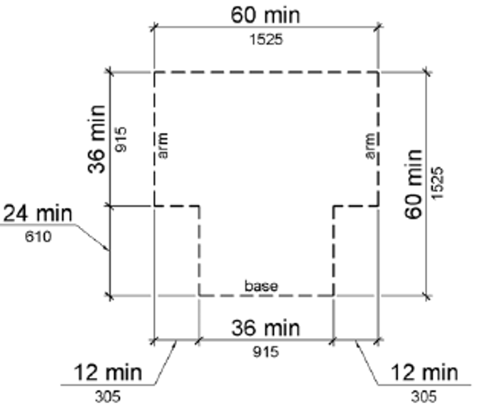
Figure 304.3.2 T-Shaped Turning Space
305.1 General.
Clear floor or ground space shall comply with 305.
305.2 Floor or Ground Surfaces.
Floor or ground surfaces of a clear floor or ground space shall comply with 302. Changes in level are not permitted.
EXCEPTION: Slopes not steeper than 1:48 shall be permitted.
305.3 Size.
The clear floor or ground space shall be 30 inches (760 mm) minimum by 48 inches (1220 mm) minimum.
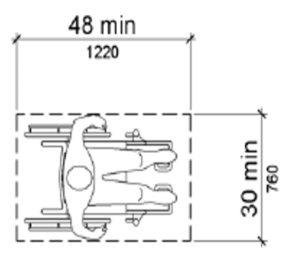
Figure 305.3 Clear Floor or Ground Space
305.4 Knee and Toe Clearance.
Unless otherwise specified, clear floor or ground space shall be permitted to include knee and toe clearance complying with 306.
305.5 Position.
Unless otherwise specified, clear floor or ground space shall be positioned for either forward or parallel approach to an element.
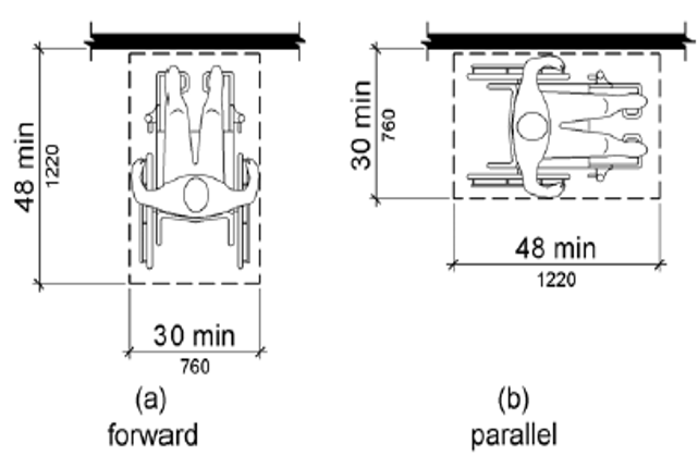
Figure 305.5 Position of Clear Floor or Ground Space
305.6 Approach.
One full unobstructed side of the clear floor or ground space shall adjoin an accessible route or adjoin another clear floor or ground space.
305.7 Maneuvering Clearance.
Where a clear floor or ground space is located in an alcove or otherwise confined on all or part of three sides, additional maneuvering clearance shall be provided in accordance with 305.7.1 and 305.7.2.
305.7.1 Forward Approach.
Alcoves shall be 36 inches (915 mm) wide minimum where the depth exceeds 24 inches (610 mm).
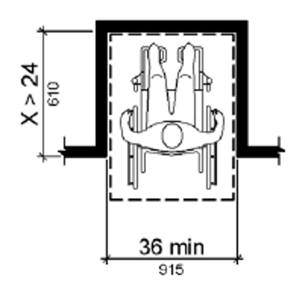
Figure 305.7.1 Maneuvering Clearance in an Alcove, Forward Approach
305.7.2 Parallel Approach.
Alcoves shall be 60 inches (1525 mm) wide minimum where the depth exceeds 15 inches (380 mm).
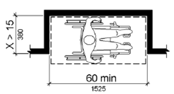
Figure 305.7.2 Maneuvering Clearance in an Alcove, Parallel Approach
306.1 General.
Where space beneath an element is included as part of clear floor or ground space or turning space, the space shall comply with 306. Additional space shall not be prohibited beneath an element but shall not be considered as part of the clear floor or ground space or turning space.
Advisory 306.1 General. Clearances are measured in relation to the usable clear floor space, not necessarily to the vertical support for an element. When determining clearance under an object for required turning or maneuvering space, care should be taken to ensure the space is clear of any obstructions.
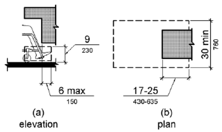
306.2.1 General.
Space under an element between the finish floor or ground and 9 inches (230 mm) above the finish floor or ground shall be considered toe clearance and shall comply with 306.2.
306.2.2 Maximum Depth.
Toe clearance shall extend 25 inches (635 mm) maximum under an element.
306.2.3 Minimum Required Depth.
Where toe clearance is required at an element as part of a clear floor space, the toe clearance shall extend 17 inches (430 mm) minimum under the element.
306.2.4 Additional Clearance.
Space extending greater than 6 inches (150 mm) beyond the available knee clearance at 9 inches (230 mm) above the finish floor or ground shall not be considered toe clearance.
306.2.5 Width.
Toe clearance shall be 30 inches (760 mm) wide minimum.
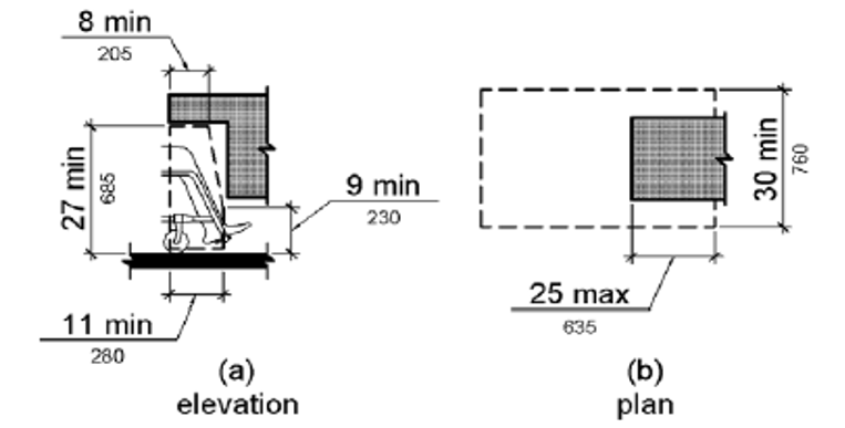
306.3.1 General.
Space under an element between 9 inches (230 mm) and 27 inches (685 mm) above the finish floor or ground shall be considered knee clearance and shall comply with 306.3.
306.3.2 Maximum Depth.
Knee clearance shall extend 25 inches (635 mm) maximum under an element at 9 inches (230 mm) above the finish floor or ground.
306.3.3 Minimum Required Depth.
Where knee clearance is required under an element as part of a clear floor space, the knee clearance shall be 11 inches (280 mm) deep minimum at 9 inches (230 mm) above the finish floor or ground, and 8 inches (205 mm) deep minimum at 27 inches (685 mm) above the finish floor or ground.
306.3.4 Clearance Reduction.
Between 9 inches (230 mm) and 27 inches (685 mm) above the finish floor or ground, the knee clearance shall be permitted to reduce at a rate of 1 inch (25 mm) in depth for each 6 inches (150 mm) in height.
306.3.5 Width.
Knee clearance shall be 30 inches (760 mm) wide minimum.
308.1 General.
Reach ranges shall comply with 308.
308.2.1 Unobstructed.
Where a forward reach is unobstructed, the high forward reach shall be 48 inches (1220 mm) maximum and the low forward reach shall be 15 inches (380 mm) minimum above the finish floor or ground.
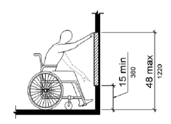
Figure 308.2.1 Unobstructed Forward Reach
308.2.2 Obstructed High Reach.
Where a high forward reach is over an obstruction, the clear floor space shall extend beneath the element for a distance not less than the required reach depth over the obstruction. The high forward reach shall be 48 inches (1220 mm) maximum where the reach depth is 20 inches (510 mm) maximum. Where the reach depth exceeds 20 inches (510 mm), the high forward reach shall be 44 inches (1120 mm) maximum and the reach depth shall be 25 inches (635 mm) maximum.
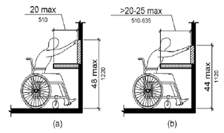
Figure 308.2.2 Obstructed High Forward Reach
308.3.1 Unobstructed.
Where a clear floor or ground space allows a parallel approach to an element and the side reach is unobstructed, the high side reach shall be 48 inches (1220 mm) maximum and the low side reach shall be 15 inches (380 mm) minimum above the finish floor or ground.
EXCEPTIONS: 1. An obstruction shall be permitted between the clear floor or ground space and the element where the depth of the obstruction is 10 inches (255 mm) maximum.
2. Operable parts of fuel dispensers shall be permitted to be 54 inches (1370 mm) maximum measured from the surface of the vehicular way where fuel dispensers are installed on existing curbs.
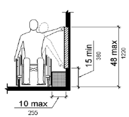
Figure 308.3.1 Unobstructed Side Reach
308.3.2 Obstructed High Reach.
Where a clear floor or ground space allows a parallel approach to an element and the high side reach is over an obstruction, the height of the obstruction shall be 34 inches (865 mm) maximum and the depth of the obstruction shall be 24 inches (610 mm) maximum. The high side reach shall be 48 inches (1220 mm) maximum for a reach depth of 10 inches (255 mm) maximum. Where the reach depth exceeds 10 inches (255 mm), the high side reach shall be 46 inches (1170 mm) maximum for a reach depth of 24 inches (610 mm) maximum.
EXCEPTIONS: 1. The top of washing machines and clothes dryers shall be permitted to be 36 inches (915 mm) maximum above the finish floor.
2. Operable parts of fuel dispensers shall be permitted to be 54 inches (1370 mm) maximum measured from the surface of the vehicular way where fuel dispensers are installed on existing curbs.
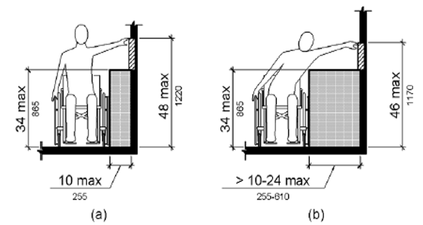
Figure 308.3.2 Obstructed High Side Reach
309.1 General.
Operable parts shall comply with 309.
309.2 Clear Floor Space.
A clear floor or ground space complying with 305 shall be provided.
309.3 Height.
Operable parts shall be placed within one or more of the reach ranges specified in 308.
309.4 Operation.
Operable parts shall be operable with one hand and shall not require tight grasping, pinching, or twisting of the wrist. The force required to activate operable parts shall be 5 pounds (22.2 N) maximum.
EXCEPTION: Gas pump nozzles shall not be required to provide operable parts that have an activating force of 5 pounds (22.2 N) maximum.
404.2.3 Doorways - Clear Width.
Door openings shall provide a clear width of 32 inches (815 mm) minimum. Clear openings of doorways with swinging doors shall be measured between the face of the door and the stop, with the door open 90 degrees. Openings more than 24 inches (610 mm) deep shall provide a clear opening of 36 inches (915 mm) minimum. There shall be no projections into the required clear opening width lower than 34 inches (865 mm) above the finish floor or ground. Projections into the clear opening width between 34 inches (865 mm) and 80 inches (2030 mm) above the finish floor or ground shall not exceed 4 inches (100 mm).
EXCEPTIONS: 1. In alterations, a projection of 5/8 inch (16 mm) maximum into the required clear width shall be permitted for the latch side stop.
2. Door closers and door stops shall be permitted to be 78 inches (1980 mm) minimum above the finish floor or ground.
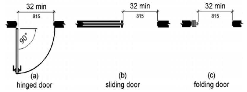
Figure 404.2.3 Clear Width of Doorways
404.2.7 Door and Gate Hardware.
Handles, pulls, latches, locks, and other operable parts on doors and gates shall comply with 309.4. Operable parts of such hardware shall be 34 inches (865 mm) minimum and 48 inches (1220 mm) maximum above the finish floor or ground. Where sliding doors are in the fully open position, operating hardware shall be exposed and usable from both sides.
User Comments/Questions
Add Comment/Question