APPENDIX A: Provisions of the Architectural Barriers Act Accessibility Standards (ABAAS)
That Are Referenced in the FSORAG Technical Provisions
The ABAAS are available at http://www.access-board.gov/guidelines-andstandards/buildings-and-sites/about-the-aba-standards/aba-standards.
F208.1 General.
Where parking spaces are provided, parking spaces shall be provided in accordance with F208.
EXCEPTION: Parking spaces used exclusively for buses, trucks, other delivery vehicles, law enforcement vehicles, or vehicular impound shall not be required to comply with F208 provided that lots accessed by the public are provided with a passenger loading zone complying with 503.
F208.2 Minimum Number.
Parking spaces complying with 502 shall be provided in accordance with Table F208.2 except as required by F208.2.1, F208.2.2, and F208.2.3. Where more than one parking facility is provided on a site, the number of accessible spaces provided on the site shall be calculated according to the number of spaces required for each parking facility.
| Total Number of Parking Spaces Provided in Parking Facility | Minimum Number of Required accessible Parking Spaces |
| 1 to 25 | 1 |
| 26 to 50 | 2 |
| 51 to 75 | 3 |
| 76 to 100 | 4 |
| 101 to 150 | 5 |
| 151 to 200 | 6 |
| 201 to 300 | 7 |
| 301 to 400 | 8 |
| 401 to 500 | 9 |
| 501 to 1000 | 2 percent of total |
| 1001 and over | 20, plus 1 for each 100, or fraction thereof, over 1000 |
F208.2.4 Van Parking Spaces.
For every six or fraction of six parking spaces required by F208.2 to comply with 502, at least one shall be a van parking space complying with 502.
F208.3 Location.
Parking facilities shall comply with F208.3
F208.3.1 General.
Parking spaces complying with 502 that serve a particular building or facility shall be located on the shortest accessible route from parking to an entrance complying with F206.4. Where parking serves more than one accessible entrance, parking spaces complying with 502 shall be dispersed and located on the shortest accessible route to the accessible entrances. In parking facilities that do not serve a particular building or facility, parking spaces complying with 502 shall be located on the shortest accessible route to an accessible pedestrian entrance of the parking facility.
304.1 General.
Turning space shall comply with 304.
304.3.1 Circular Space.
The turning space shall be a space of 60 inches (1525 mm) diameter minimum. The space shall be permitted to include knee and toe clearance complying with 306.
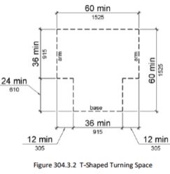
304.3.2 T-Shaped Space.
The turning space shall be a T-shaped space within a 60 inch (1525 mm) square minimum with arms and base 36 inches (915 mm) wide minimum. Each arm of the T shall be clear of obstructions 12 inches (305 mm) minimum in each direction and the base shall be clear of obstructions 24 inches (610 mm) minimum. The space shall be permitted to include knee and toe clearance complying with 306 only at the end of either the base or one arm.
305.1 General.
Clear floor or ground space shall comply with 305.
305.2 Floor or Ground Surfaces.
Floor or ground surfaces of a clear floor or ground space shall comply with 302. Changes in level are not permitted.
EXCEPTION: Slopes not steeper than 1:48 shall be permitted.
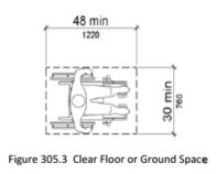
305.3 Size.
The clear floor or ground space shall be 30 inches (760 mm) minimum by 48 inches (1220 mm) minimum.
305.4 Knee and Toe Clearance.
Unless otherwise specified, clear floor or ground space shall be permitted to include knee and toe clearance complying with 306.
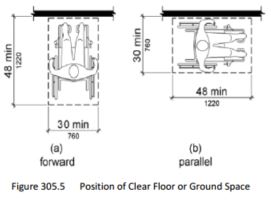
305.5 Position.
Unless otherwise specified, clear floor or ground space shall be positioned for either forward or parallel approach to an element.
305.6 Approach.
One full unobstructed side of the clear floor or ground space shall adjoin an accessible route or adjoin another clear floor or ground space.
305.7 Maneuvering Clearance.
Where a clear floor or ground space is located in an alcove or otherwise confined on all or part of three sides, additional maneuvering clearance shall be provided in accordance with 305.7.1 and 305.7.2.
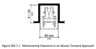
305.7.1 Forward Approach.
Alcoves shall be 36 inches (915 mm)wide minimum where the depth exceeds 24 inches (610 mm).
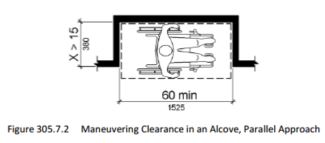
305.7.2 Parallel Approach.
Alcoves shall be 60 inches (1525 mm) wide minimum where the depth exceeds 15 inches (380 mm).
306.1 General.
Where space beneath an element is included as part of clear floor or ground space or turning space, the space shall comply with 306. Additional space shall not be prohibited beneath an element but shall not be considered as part of the clear floor or ground space or turning space.
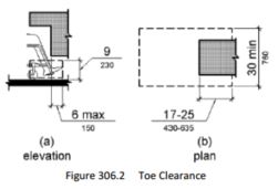
306.2.1 General.
Space under an element between the finish floor or ground and 9 inches (230 mm) above the finish floor or ground shall be considered toe clearance and shall comply with 306.2.
306.2.2 Maximum Depth.
Toe clearance shall extend 25 inches (635 mm) maximum under an element.
306.2.3 Minimum Required Depth.
Where toe clearance is required at an element as part of a clear floor space, the toe clearance shall extend 17 inches (430 mm) minimum under the element.
306.2.4 Additional Clearance.
Space extending greater than 6 inches (150 mm) beyond the available knee clearance at 9 inches (230 mm) above the finish floor or ground shall not be considered toe clearance.
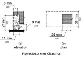
306.3.1 General.
Space under an element between 9 inches (230 mm) and 27 inches (685 mm) above the finish floor or ground shall be considered knee clearance and shall comply with 306.3.
306.3.2 Maximum Depth.
Knee clearance shall extend 25 inches (635 mm) maximum under an element at 9 inches (230 mm) above the finish floor or ground.
306.3.3 Minimum Required Depth.
Where knee clearance is required under an element as part of a clear floor space, the knee clearance shall be 11 inches (280 mm) deep minimum at 9 inches (230 mm) above the finish floor or ground, and 8 inches (205 mm) deep minimum at 27 inches (685 mm) above the finish floor or ground.
306.3.4 Clearance Reduction.
Between 9 inches (230 mm) and 27 inches (685 mm) above the finish floor or ground, the knee clearance shall be permitted to reduce at a rate of 1 inch (25 mm) in depth for each 6 inches (150 mm) in height.
308.1 General.
Reach ranges shall comply with 308.
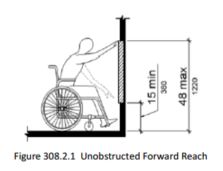
308.2.1 Unobstructed.
Where a forward reach is unobstructed, the high forward reach shall be 48 inches (1220 mm) maximum and the low forward reach shall be 15 inches (380 mm) minimum above the finish floor or ground.
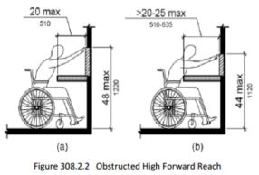
308.2.2 Obstructed High Reach.
Where a high forward reach is over an obstruction, the clear floor space shall extend beneath the element for a distance not less than the required reach depth over the obstruction. The high forward reach shall be 48 inches (1220 mm) maximum where the reach depth is 20 inches (510 mm) maximum. Where the reach depth exceeds 20 inches (510 mm), the high forward reach shall be 44 inches (1120 mm) maximum and the reach depth shall be 25 inches (635 mm) maximum.
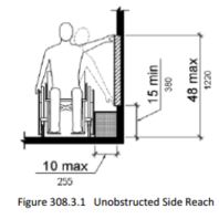
308.3.1 Unobstructed.
Where a clear floor or ground space allows a parallel approach to an element and the side reach is unobstructed, the high side reach shall be 48 inches (1220 mm) maximum and the low side reach shall be 15 inches (380 mm) minimum above the finish floor or ground.
EXCEPTIONS: 1. An obstruction shall be permitted between the clear floor or ground space and the element where the depth of the obstruction is 10 inches (255 mm) maximum. 2. Operable parts of fuel dispensers shall be permitted to be 54 inches (1370 mm) maximum measured from the surface of the vehicular way where fuel dispensers are installed on existing curbs.
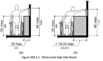
308.3.2 Obstructed High Reach.
Where a clear floor or ground space allows a parallel approach to an element and the high side reach is over an obstruction, the height of the obstruction shall be 34 inches (865 mm) maximum and the depth of the obstruction shall be 24 inches (610 mm) maximum. The high side reach shall be 48 inches (1220 mm) maximum for a reach depth of 10 inches (255 mm) maximum. Where the reach depth exceeds 10 inches (255 mm), the high side reach shall be 46 inches (1170 mm) maximum for a reach depth of 24 inches (610 mm) maximum.
EXCEPTIONS: 1. The top of washing machines and clothes dryers shall be permitted to be 36 inches (915 mm) maximum above the finish floor.
2. Operable parts of fuel dispensers shall be permitted to be 54 inches (1370 mm) maximum measured from the surface of the vehicular way where fuel dispensers are installed on existing curbs.
309.1 General.
Operable parts shall comply with 309.
309.2 Clear Floor Space.
A clear floor or ground space complying with 305 shall be provided.
309.3 Height.
Operable parts shall be placed within one or more of the reach ranges specified in 308.
309.4 Operation.
Operable parts shall be operable with one hand and shall not require tight grasping, pinching, or twisting of the wrist. The force required to activate operable parts shall be 5 pounds (22.2 N) maximum.
EXCEPTION: Gas pump nozzles shall not be required to provide operable parts that have an activating force of 5 pounds (22.2 N) maximum.
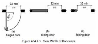
404.2.3 Doorways - Clear Width.
Door openings shall provide a clear width of 32 inches (815 mm) minimum. Clear openings of doorways with swinging doors shall be measured between the face of the door and the stop, with the door open 90 degrees. Openings more than 24 inches (610 mm) deep shall provide a clear opening of 36 inches (915 mm) minimum. There shall be no projections into the required clear opening width lower than 34 inches (865 mm) above the finish floor or ground. Projections into the clear opening width between 34 inches (865 mm) and 80 inches (2030 mm) above the finish floor or ground shall not exceed 4 inches (100 mm).
EXCEPTIONS: 1. In alterations, a projection of 5/8 inch (16 mm) maximum into the required clear width shall be permitted for the latch side stop.
2. Door closers and door stops shall be permitted to be 78 inches (1980 mm) minimum above the finish floor or ground.
404.2.7 Door and Gate Hardware.
Handles, pulls, latches, locks, and other operable parts on doors and gates shall comply with 309.4. Operable parts of such hardware shall be 34 inches (865 mm) minimum and 48 inches (1220 mm) maximum above the finish floor or ground. Where sliding doors are in the fully open position, operating hardware shall be exposed and usable from both sides.
405.9 Edge Protection.
Edge protection complying with 405.9.1 or 405.9.2 shall be provided on each side of ramp runs and at each side of ramp landings.
EXCEPTIONS: 1. Edge protection shall not be required on ramps that are not required to have handrails and have sides complying with 406.3.
2. Edge protection shall not be required on the sides of ramp landings serving an adjoining ramp run or stairway.
3. Edge protection shall not be required on the sides of ramp landings having a vertical drop-off of 1/2 inch (13 mm) maximum within 10 inches (255 mm) horizontally of the minimum landing area specified in 405.7.
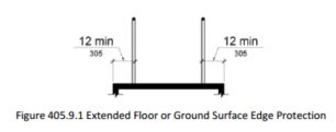
405.9.1 Extended Floor or Ground Surface.
The floor or ground surface of the ramp run or landing shall extend 12 inches (305 mm) minimum beyond the inside face of a handrail complying with 505.
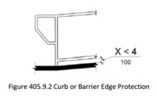
405.9.2 Curb or Barrier.
A curb or barrier shall be provided that prevents the passage of a 4 inch (100 mm) diameter sphere, where any portion of the sphere is within 4 inches (100 mm) of the finish floor or ground surface.
405.10 Wet Conditions.
Landings subject to wet conditions shall be designed to prevent the accumulation of water.
502.1 General.
Car and van parking spaces shall comply with 502. Where parking spaces are marked with lines, width measurements of parking spaces and access aisles shall be made from the centerline of the markings.
EXCEPTION: Where parking spaces or access aisles are not adjacent to another parking space or access aisle, measurements shall be permitted to include the full width of the line defining the parking space or access aisle.
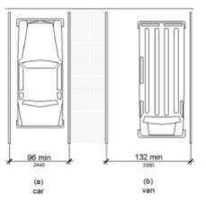
502.2 Vehicle Spaces.
Car parking spaces shall be 96 inches (2440 mm) wide minimum and van parking spaces shall be 132 inches (3350 mm) wide minimum, shall be marked to define the width, and shall have an adjacent access aisle complying with 502.3.
EXCEPTION: Van parking spaces shall be permitted to be 96 inches (2440 mm) wide minimum where the access aisle is 96 inches (2440 mm) wide minimum.
502.3 Access Aisle.
Access aisles serving parking spaces shall comply with 502.3. Access aisles shall adjoin an accessible route. Two parking spaces shall be permitted to share a common access aisle.
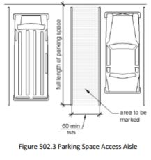
502.3.1 Width.
Access aisles serving car and van parking spaces shall be 60 inches (1525 mm) wide minimum.
502.3.2 Length.
Access aisles shall extend the full length of the parking spaces they serve.
502.3.3 Marking.
Access aisles shall be marked so as to discourage parking in them.
502.3.4 Location.
Access aisles shall not overlap the vehicular way. Access aisles shall be permitted to be placed on either side of the parking space except for angled van parking spaces which shall have access aisles located on the passenger side of the parking spaces.
502.4 Floor or Ground Surfaces.
Parking spaces and access aisles serving them shall comply with 302. Access aisles shall be at the same level as the parking spaces they serve. Changes in level are not permitted.
EXCEPTION: Slopes not steeper than 1:48 shall be permitted.
502.6 Identification.
Parking space identification signs shall include the International Symbol of Accessibility complying with 703.7.2.1. Signs identifying van parking spaces shall contain the designation "van accessible." Signs shall be 60 inches (1525 mm) minimum above the finish floor or ground surface measured to the bottom of the sign.
502.7 Relationship to Accessible Routes.
Parking spaces and access aisles shall be designed so that cars and vans, when parked, cannot obstruct the required clear width of adjacent accessible routes.
505.1 General.
Handrails provided along walking surfaces complying with 403, required at ramps complying with 405, and required at stairs complying with 504 shall comply with 505.
505.2 Where Required.
Handrails shall be provided on both sides of stairs and ramps.
EXCEPTION: In assembly areas, handrails shall not be required on both sides of aisle ramps where a handrail is provided at either side or within the aisle width.
505.3 Continuity.
Handrails shall be continuous within the full length of each stair flight or ramp run. Inside handrails on switchback or dogleg stairs and ramps shall be continuous between flights or runs.
EXCEPTION: In assembly areas, handrails on ramps shall not be required to be continuous in aisles serving seating.
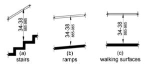
505.4 Height.
Top of gripping surfaces of handrails shall be 34 inches (865 mm) minimum and 38 inches (965 mm) maximum vertically above walking surfaces, stair nosings, and ramp surfaces. Handrails shall be at a consistent height above walking surfaces, stair nosings, and ramp surfaces.
Figure 505.4 Handrail Height
505.5 Clearance.
Clearance between handrail gripping surfaces and adjacent surfaces shall be 1 1/2 inches (38 mm) minimum.

505.6 Gripping Surface.
Handrail gripping surfaces shall be continuous along their length and shall not be obstructed along their tops or sides. The bottoms of handrail gripping surfaces shall not be obstructed for more than 20 percent of their length. Where provided, horizontal projections shall occur 1 1/2 inches (38 mm) minimum below the bottom of the handrail gripping surface.
EXCEPTIONS: 1. Where handrails are provided along walking surfaces with slopes not steeper than 1:20, the bottoms of handrail gripping surfaces shall be permitted to be obstructed along their entire length where they are integral to crash rails or bumper guards.
2. The distance between horizontal projections and the bottom of the gripping surface shall be permitted to be reduced by 1/8 inch (3.2 mm) for each 1/2 inch (13 mm) of additional handrail perimeter dimension that exceeds 4 inches (100 mm).
505.7 Cross Section.
Handrail gripping surfaces shall have a cross section complying with 505.7.1 or 505.7.2.
505.7.1 Circular Cross Section.
Handrail gripping surfaces with a circular cross section shall have an outside diameter of 1 1/4 inches (32 mm) minimum and 2 inches (51 mm) maximum.
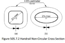
505.7.2 Non-Circular Cross Sections.
Handrail gripping surfaces with a non-circular cross section shall have a perimeter dimension of 4 inches (100 mm) minimum and 6 1/4 inches (160 mm) maximum, and a cross-section dimension of 2 1/4 inches (57 mm) maximum.
505.8 Surfaces.
Handrail gripping surfaces and any surfaces adjacent to them shall be free of sharp or abrasive elements and shall have rounded edges.
505.9 Fittings.
Handrails shall not rotate within their fittings.
505.10 Handrail Extensions.
Handrail gripping surfaces shall extend beyond and in the same direction of stair flights and ramp runs in accordance with 505.10.
EXCEPTIONS: 1. Extensions shall not be required for continuous handrails at the inside turn of switchback or dogleg stairs and ramps.
2. In assembly areas, extensions shall not be required for ramp handrails in aisles serving seating where the handrails are discontinuous to provide access to seating and to permit crossovers within aisles.
3. In alterations, full extensions of handrails shall not be required where such extensions would be hazardous due to plan configuration.
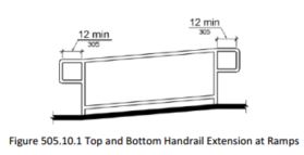
505.10.1 Top and Bottom Extension at Ramps.
Ramp handrails shall extend horizontally above the landing for 12 inches (305 mm) minimum beyond the top and bottom of ramp runs. Extensions shall return to a wall, guard, or the landing surface, or shall be continuous to the handrail of an adjacent ramp run.
505.10.2 Top Extension at Stairs.
At the top of a stair flight, handrails shall extend horizontally above the landing for 12 inches (305 mm) minimum beginning directly above the first riser nosing. Extensions shall return to a wall, guard, or the landing surface, or shall be continuous to the handrail of an adjacent stair flight.
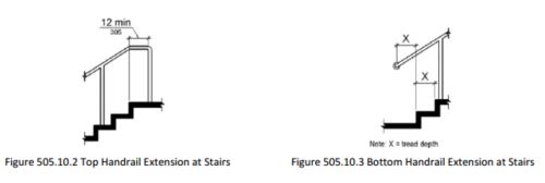
505.10.3 Bottom Extension at Stairs.
At the bottom of a stair flight, handrails shall extend at the slope of the stair flight for a horizontal distance at least equal to one tread depth beyond the last riser nosing. Extension shall return to a wall, guard, or the landing surface, or shall be continuous to the handrail of an adjacent stair flight.
603 Toilet and Bathing Rooms
(This section is to be used for toilet buildings with a single riser such as SSTs, but not for pit toilets. See definition of pit toilet in Technical Provisions section of FSORAG.)
603.1 General.
Toilet and bathing rooms shall comply with 603.
603.2 Clearances.
Clearances shall comply with 603.2.
603.2.1 Turning Space.
Turning space complying with 304 shall be provided within the room.
603.2.2 Overlap.
Required clear floor spaces, clearance at fixtures, and turning space shall be permitted to overlap.
603.2.3 Door Swing.
Doors shall not swing into the clear floor space or clearance required for any fixture. Doors shall be permitted to swing into the required turning space.
EXCEPTIONS: 1. Doors to a toilet room or bathing room for a single occupant accessed only through a private office and not for common use or public use shall be permitted to swing into the clear floor space or clearance provided the swing of the door can be reversed to comply with 603.2.3.
2. Where the toilet room or bathing room is for individual use and a clear floor space complying with 305.3 is provided within the room beyond the arc of the door swing, doors shall be permitted to swing into the clear floor space or clearance required for any fixture.
603.3 Mirrors.
Mirrors located above lavatories or countertops shall be installed with the bottom edge of the reflecting surface 40 inches (1015 mm) maximum above the finish floor or ground. Mirrors not located above lavatories or countertops shall be installed with the bottom edge of the reflecting surface 35 inches (890 mm) maximum above the finish floor or ground.
Advisory 603.3 Mirrors. A single full-length mirror can accommodate a greater number of people, including children. In order for mirrors to be usable by people who are ambulatory and people and people who use wheelchairs, the top edge of mirrors should be 74 inches (1880 mm) minimum from the floor or ground
603.4 Coat Hooks and Shelves.
Coat hooks shall be located within one of the reach ranges specified in 308. Shelves shall be located 40 inches (1015 mm) minimum and 48 inches (1220 mm) maximum above the finish floor.
604 Water Closets and Toilet Compartments
(This section is to be used for toilet buildings with multiple risers provided at recreation sites with a FS Recreation Site Development Scale of 3 or higher, and for the Exception under Pit Toilets in General Forest Areas FSORAG 6.6).
604.1 General.
Water closets and toilet compartments shall comply with 604.2 through 604.8.
EXCEPTION: Water closets and toilet compartments for children's use shall be permitted to comply with 604.9.
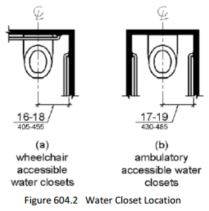
604.2 Location.
The water closet shall be positioned with a wall or partition to the rear and to one side. The centerline of the water closet shall be 16 inches (405 mm) minimum to 18 inches (455 mm) maximum from the side wall or partition, except that the water closet shall be 17 inches (430 mm) minimum and 19 inches (485 mm) maximum from the side wall or partition in the ambulatory accessible toilet compartment specified in 604.8.2. Water closets shall be arranged for a left-hand or right-hand approach.
604.3 Clearance.
Clearances around water closets and in toilet compartments shall comply with 604.3.
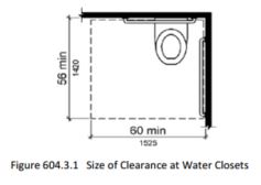
604.3.1 Size.
Clearance around a water closet shall be 60 inches (1525 mm) minimum measured perpendicular from the side wall and 56 inches (1420 mm) minimum measured perpendicular from the rear wall.
604.3.2 Overlap.
The required clearance around the water closet shall be permitted to overlap the water closet, associated grab bars, dispensers, sanitary napkin disposal units, coat hooks, shelves, accessible routes, clear floor space and clearances required at other fixtures, and the turning space. No other fixtures or obstructions shall be located within the required water closet clearance.
EXCEPTION: In residential dwelling units, a lavatory complying with 606 shall be permitted on the rear wall 18 inches (455 mm) minimum from the water closet centerline where the clearance at the water closet is 66 inches (1675 mm) minimum measured perpendicular from the rear wall.
604.4 Seats.
The seat height of a water closet above the finish floor shall be 17 inches (430 mm) minimum and 19 inches (485 mm) maximum measured to the top of the seat. Seats shall not be sprung to return to a lifted position.
EXCEPTIONS: 1. A water closet in a toilet room for a single occupant accessed only through a private office and not for common use or public use shall not be required to comply with 604.4. 2. In residential dwelling units, the height of water closets shall be permitted to be 15 inches (380 mm) minimum and 19 inches (485 mm) maximum above the finish floor measured to the top of the seat.
604.5 Grab Bars.
Grab bars for water closets shall comply with 609. Grab bars shall be provided on the side wall closest to the water closet and on the rear wall.
Advisory 604.5 Grab Bars Exception 2. Reinforcement must be sufficient to permit the installation of rear and side wall grab bars that fully meet all accessibility requirements including, but not limited to, required length, installation height, and structural strength.
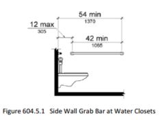
604.5.1 Side Wall.
The side wall grab bar shall be 42 inches (1065 mm) long minimum, located 12 inches (305 mm) maximum from the rear wall and extending 54 inches (1370 mm) minimum from the rear wall.
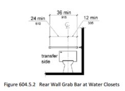
604.5.2 Rear Wall.
The rear wall grab bar shall be 36 inches (915 mm) long minimum and extend from the centerline of the water closet 12 inches (305 mm) minimum on one side and 24 inches (610 mm) minimum on the other side.
EXCEPTIONS: 1. The rear grab bar shall be permitted to be 24 inches (610 mm) long minimum, centered on the water closet, where wall space does not permit a length of 36 inches (915 mm) minimum due to the location of a recessed fixture adjacent to the water closet.
2. Where an administrative authority requires flush controls for flush valves to be located in a position that conflicts with the location of the rear grab bar, then the rear grab bar shall be permitted to be split or shifted to the open side of the toilet area.
604.6 Flush Controls.
Flush controls shall be hand operated or automatic. Hand operated flush controls shall comply with 309. Flush controls shall be located on the open side of the water closet except in ambulatory accessible compartments complying with 604.8.2.
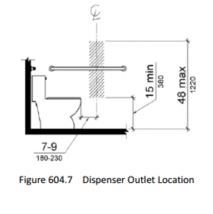
604.7 Dispensers.
Toilet paper dispensers shall comply with 309.4 and shall be 7 inches (180 mm) minimum and 9 inches (230 mm) maximum in front of the water closet measured to the centerline of the dispenser. The outlet of the dispenser shall be 15 inches (380 mm) minimum and 48 inches (1220 mm) maximum above the finish floor and shall not be located behind grab bars. Dispensers shall not be of a type that controls delivery or that does not allow continuous paper flow.
Advisory 604.7 Dispensers. If toilet paper dispensers are installed above the side wall grab bar, the outlet of the toilet paper dispenser must be 48 inches (1220 mm) maximum above the finish floor and the top of the gripping surface of the grab bar must be 33 inches (840 mm) minimum and 36 inches (915 mm) maximum above the finish floor.
608.6 Shower Spray Unit and Water.
A shower spray unit with a hose 59 inches (1500 mm) long minimum that can be used both as a fixed-position shower head and as a hand-held shower shall be provided. The shower spray unit shall have an on/off control with a non-positive shut-off. If an adjustable-height shower head on a vertical bar is used, the bar shall be installed so as not to obstruct the use of grab bars. Shower spray units shall deliver water that is 120°F (49°C) maximum.
EXCEPTION: A fixed shower head located at 48 inches (1220 mm) maximum above the shower finish floor shall be permitted instead of a hand-held spray unit in facilities that are not medical care facilities, longterm care facilities, transient lodging guest rooms, or residential dwelling units.
Advisory 608.6 Shower Spray Unit and Water. Ensure that hand-held shower spray units are capable of delivering water pressure substantially equivalent to fixed shower heads.
609.1 General.
Grab bars in toilet facilities and bathing facilities shall comply with 609.
609.2 Cross Section.
Grab bars shall have a cross section complying with 609.2.1 or 609.2.2.
609.2.1 Circular Cross Section.
Grab bars with circular cross sections shall have an outside diameter of 1 1/4 inches (32 mm) minimum and 2 inches (51 mm) maximum.
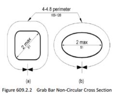
609.2.2 Non-Circular Cross Section.
Grab bars with non-circular cross sections shall have a cross-section dimension of 2 inches (51 mm) maximum and a perimeter dimension of 4 inches (100 mm) minimum and 4.8 inches (120 mm) maximum.
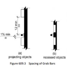
609.3 Spacing.
The space between the wall and the grab bar shall be 1 1/2 inches (38 mm). The space between the grab bar and projecting objects below and at the ends shall be 1 1/2 inches (38 mm) minimum. The space between the grab bar and projecting objects above shall be 12 inches (305 mm) minimum.
EXCEPTION: The space between the grab bars and shower controls, shower fittings, and other grab bars above shall be permitted to be 1 1/2 inches (38 mm) minimum.
609.4 Position of Grab Bars.
Grab bars shall be installed in a horizontal position, 33 inches (840 mm) minimum and 36 inches (915 mm) maximum above the finish floor measured to the top of the gripping surface, except that at water closets for children's use complying with 604.9, grab bars shall be installed in a horizontal position 18 inches (455 mm) minimum and 27 inches (685 mm) maximum above the finish floor measured to the top of the gripping surface. The height of the lower grab bar on the back wall of a bathtub shall comply with 607.4.1.1 or 607.4.2.1.
609.5 Surface Hazards.
Grab bars and any wall or other surfaces adjacent to grab bars shall be free of sharp or abrasive elements and shall have rounded edges.
609.6 Fittings.
Grab bars shall not rotate within their fittings.
609.7 Installation.
Grab bars shall be installed in any manner that provides a gripping surface at the specified locations and that does not obstruct the required clear floor space.
609.8 Structural Strength.
Allowable stresses shall not be exceeded for materials used when a vertical or horizontal force of 250 pounds (1112 N) is applied at any point on the grab bar, fastener, mounting device, or supporting structure.
F216.1 General.
Signs shall be provided in accordance with F216 and shall comply with 703.
703.7 Symbols of Accessibility.
Symbols of accessibility shall comply with 703.7.
703.7.1 Finish and Contrast.
Symbols of accessibility and their background shall have a non-glare finish. Symbols of accessibility shall contrast with their background with either a light symbol on a dark background or a dark symbol on a light background.
Advisory 703.7.1 Finish and Contrast. Signs are more legible for persons with low vision when characters contrast as much as possible with their background. Additional factors affecting the ease with which the text can be distinguished from its background include shadows cast by lighting sources, surface glare, and the uniformity of the text and background colors and textures.
703.7.2.1 International Symbol of Accessibility.
The International Symbol of Accessibility shall comply with Figure 703.7.2.1.
This symbol is to be posted at the following locations:
At designated accessible parking spaces (F216.5)
- where a total of 5 or more parking spaces, including accessible parking spaces, are at a site (F216.5.1)
- van parking space must be signed as “van accessible”.(F216.5)
If the main entrance to a building is not accessible, the ISA and an arrow to be posted to direct to closest accessible entrance. (F216.6)
Accessible restrooms and bathing facilities.(F216.8)
Accessible Area of Refuge inside multi story buildings (F216.4.2)
Accessible means of egress out of a building (F216.4.3)
If an entrance or elevator is not accessible, the ISA and an arrow are to be posted to direct to closest accessible (F216.7)
903.1 General.
Benches shall comply with 903.
903.2 Clear Floor or Ground Space.
Clear floor or ground space complying with 305 shall be provided and shall be positioned at the end of the bench seat and parallel to the short axis of the bench.
903.3 Size.
Benches shall have seats that are 42 inches (1065 mm) long minimum and 20 inches (510 mm) deep minimum and 24 inches (610 mm) deep maximum.
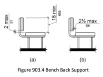
903.4 Back Support.
The bench shall provide for back support or shall be affixed to a wall. Back support shall be 42 inches (1065 mm) long minimum and shall extend from a point 2 inches (51 mm) maximum above the seat surface to a point 18 inches (455 mm) minimum above the seat surface. Back support shall be 2 1/2 inches (64 mm) maximum from the rear edge of the seat measured horizontally.
903.5 Height.
The top of the bench seat surface shall be 17 inches (430 mm) minimum and 19 inches (485 mm) maximum above the finish floor or ground.
903.6 Structural Strength.
Allowable stresses shall not be exceeded for materials used when a vertical or horizontal force of 250 pounds (1112 N) is applied at any point on the seat, fastener, mounting device, or supporting structure.
User Comments/Questions
Add Comment/Question