2019 California Standards for Accessible Design Guide (effective January 1, 2020 with July 1, 2021 amendments)
DIVISION 4: ACCESSIBLE ROUTES
11B-401.1 Scope.
The provisions of Division 4 shall apply where required by Division 2 or where referenced by a requirement in this chapter.
11B-402.2 Components.
Accessible routes shall consist of one or more of the following components: walking surfaces with a running slope not steeper than 1:20, doorways, ramps, curb ramps excluding the flared sides, elevators, and platform lifts. All components of an accessible route shall comply with the applicable requirements of Division 4.

11B-403.1 General.
Walking surfaces that are a part of an accessible route shall comply with Section 11B-403.
11B-403.2 Floor or ground surface.
Floor or ground surfaces shall comply with Section 11B-302.
11B-403.3 Slope.
The running slope of walking surfaces shall not be steeper than 1:20. The cross slope of walking surfaces shall not be steeper than 1:48.
Exception: The running slope of sidewalks shall not exceed the general grade established for the adjacent street or highway.

When the running slope of a walking surface exceeds 5%, it must comply with the accessibility requirements for ramps.
A sloping sidewalk with a running slope in excess of 5% is excluded from ramp requirements for landings and handrails but it must comply with cross-slope and width requirements. ◼
ETA Editor's Note
The 2019 CBC Exception at 11B-403.3 is not present in the 2010 ADA Standards. Therefore, technically, the 2010 ADA Standards are more stringent with regard to the slope of sidewalks at streets or highways. CBC does not define street or highway but does define sidewalk as " ... contiguous to a street used by the public." It is inferable, whether intended or not, that sidewalks serving as accessible routes alongside private roadways are not excepted from the slope limitation.
In 2011, the U.S. Access Board published in the Federal Register its Proposed Guidelines for Pedestrian Facilities in the Public Right-Of-Way, along with a Notice of Proposed Rulemaking. The public comment period was concluded in 2012, and the guidelines are in the Final Rulemaking stage now. Until these guidelines become law, the Access Board is offering guidance on its website, where one can also request technical assistance and/or sign up for updates as to the rulemaking status: http://www.access-board.gov/guidelines-and-standards/streets-sidewalks/public-rights-of-way/.
In 2013, in response to feedback, the U.S. Access Board issued a proposed Supplemental Rule to address accessibility for Shared Use Paths (used by pedestrians, bicyclists, and others for transportation or recreation), distinguished from sidewalks, as well as from trails. More information about this rulemaking process is available on the Access Board’s website: https://www.access-board.gov/guidelines-and-standards/streets-sidewalks/shared-use-paths.
11B-403.4 Changes in level.
Changes in level shall comply with Section 11B-303.
11B-403.5 Clearances.
Walking surfaces shall provide clearances complying with Section 11B-403.5.
Exception: Within employee work areas, clearances on common use circulation paths shall be permitted to be decreased by work area equipment provided that the decrease is essential to the function of the work being performed.
11B-403.5.1 Clear width.
Except as provided in Sections 11B-403.5.2 and 11B-403.5.3, the clear width of walking surfaces shall be 36 inches (914 mm) minimum.
Exceptions:
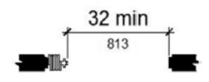
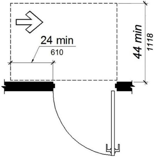
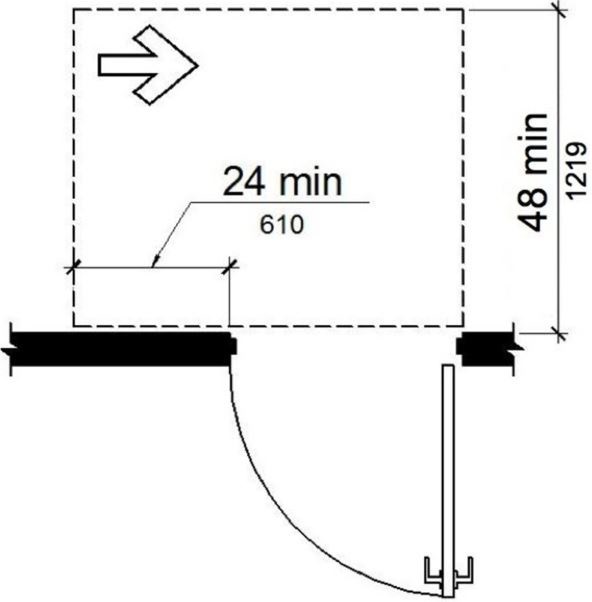
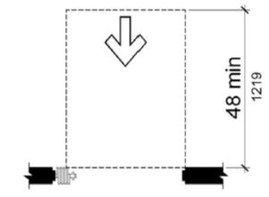
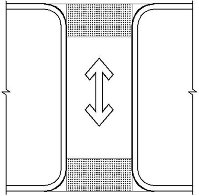
- The clear width shall be permitted to be reduced to 32 inches (813 mm) minimum for a length of 24 inches (610 mm) maximum provided that reduced width segments are separated by segments that are 48 inches (1219 mm) long minimum and 36 inches (914 mm) wide minimum.
- The clear width for walking surfaces in corridors serving an occupant load of 10 or more shall be 44 inches (1118 mm) minimum.
- The clear width for sidewalks and walks shall be 48 inches (1219 mm) minimum. When, because of right-of-way restrictions, natural barriers or other existing conditions, the enforcing agency determines that compliance with the 48-inch (1219 mm) clear sidewalk width would create an unreasonable hardship, the clear width may be reduced to 36 inches (914 mm).
- The clear width for aisles shall be 36 inches (914 mm) minimum if serving elements on only one side, and 44 inches (1118 mm) minimum if serving elements on both sides.
- The clear width for accessible routes to accessible toilet compartments shall be 44 inches (1118 mm) except for door-opening widths and door swings.
ETA Editor's Note
CBC Exceptions 2, 3 and 4 at 11B-403.5.1 are not present in the 2010 ADA Standards. Therefore, CBC requirements related to the clear width of accessible routes are more stringent.
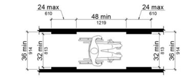
FIGURE 11B-403.5.1 CLEAR WIDTH OF AN ACCESSIBLE ROUTE
11B-403.5.2 Clear width at turn.
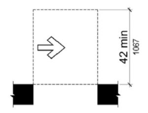
Where the accessible route makes a 180 degree turn around an element which is less than 48 inches (1219 mm) wide, clear width shall be 42 inches (1067 mm) minimum approaching the turn, 48 inches (1219 mm) minimum at the turn and 42 inches (1067 mm) minimum leaving the turn.
Exception: Where the clear width at the turn is 60 inches (1524 mm) minimum compliance with Section 11B-403.5.2 shall not be required.
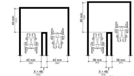
FIGURE 11B-403.5.2 CLEAR WIDTH AT TURN
11B-403.5.3 Passing spaces.
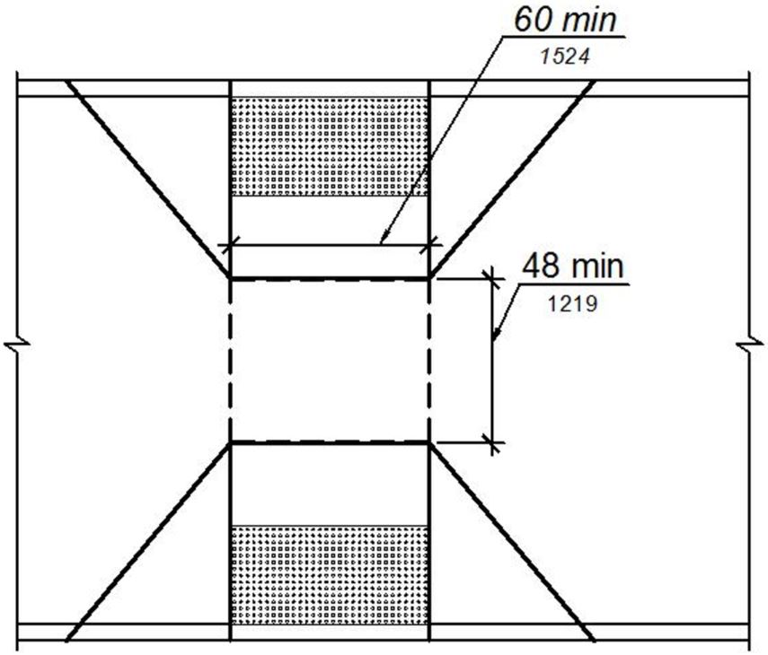
An accessible route with a clear width less than 60 inches (1524 mm) shall provide passing spaces at intervals of 200 feet (60,960 mm) maximum. Passing spaces shall be either: a space 60 inches (1524 mm) minimum by 60 inches (1524 mm) minimum; or, an intersection of two walking surfaces providing a T-shaped space complying with Section 11B-304.3.2 where the base and arms of the T-shaped space extend 48 inches (1219 mm) minimum beyond the intersection.
11B-403.6 Handrails.
Where handrails are provided along walking surfaces with running slopes not steeper than 1:20 they shall comply with Section 11B-505.

11B-403.7 Continuous gradient.
All walks with continuous gradients shall have resting areas, 60 inches (1524 mm) in length, at intervals of 400 feet (121,920 mm) maximum. The resting area shall be at least as wide as the walk. The slope of the resting area in all directions shall be 1:48 maximum.
ETA Editor's Note
CBC requirement 11B-403.7 is not present in the 2010 ADA Standards. Therefore, CBC requirements related to continuous gradients are more stringent.
11B-404.1 General.
Doors, doorways, and gates that are part of an accessible route shall comply with Section 11B-404.
Exceptions:
- Doors, doorways, and gates designed to be operated only by security personnel shall not be required to comply with Sections 11B-404.2.7, 11B-404.2.8, 11B-404.2.9, 11B-404.3.2 and 11B-404.3.4 through 11B-404.3.7. A sign visible from the approach side complying with Section 11B-703.5 shall be posted stating “Entry restricted and controlled by security personnel”.
- At detention and correctional facilities, doors, doorways, and gates designed to be operated only by security personnel shall not be required to comply with Sections 11B-404.2.7, 11B-404.2.8, 11B-404.2.9, 11B-404.3.2 and 11B-404.3.4 through 11B-404.3.7.
[2010 ADA Standards] EXCEPTION: Doors, doorways, and gates designed to be operated only by security personnel shall not be required to comply with 404.2.7, 404.2.8, 404.2.9, 404.3.2 and 404.3.4 through 404.3.7.

ETA Editor's Note
CBC provides a second exception at 11B-404.1 to distinguish doors that are operated only by security personnel at detention and correctional facilities vs. other facility types. The latter are required to have an informational sign, while the former are not.
11B-404.2 Manual doors, doorways, and manual gates
Manual doors and doorways and manual gates intended for user passage shall comply with Section 11B-404.2.
11B-404.2.1 Revolving doors, gates, and turnstiles.
Revolving doors, revolving gates, and turnstiles shall not be part of an accessible route.
11B-404.2.2 Double-leaf doors and gates.
At least one of the active leaves of doorways with two leaves shall comply with Sections 11B-404.2.3 and 11B-404.2.4.
11B-404.2.3 Clear width.
Door openings shall provide a clear width of 32 inches (813 mm) minimum. Clear openings of doorways with swinging doors shall be measured between the face of the door and the stop, with the door open 90 degrees. Openings more than 24 inches (610 mm) deep shall provide a clear opening of 36 inches (914 mm) minimum. There shall be no projections into the required clear opening width lower than 34 inches (864 mm) above the finish floor or ground. Projections into the clear opening width between 34 inches (864 mm) and 80 inches (2032 mm) above the finish floor or ground shall not exceed 4 inches (102 mm).
Exceptions:
- In alterations, a projection of 5/8 inch (15.9 mm) maximum into the required clear width shall be permitted for the latch side stop.
- Door closers and door stops shall be permitted to be 78 inches (1981 mm) minimum above the finish floor or ground.
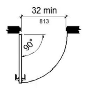
(a) hinged door
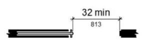
(b) sliding door
(c) folding door
FIGURE 11B-404.2.3 CLEAR WIDTH OF DOORWAYS
11B-404.2.4 Maneuvering clearances.
Minimum maneuvering clearances at doors and gates shall comply with Section 11B-404.2.4. Maneuvering clearances shall extend the full width of the doorway and the required latch side or hinge side clearance.
Exception: Reserved.
[2010 ADA Standards] EXCEPTION: Entry doors to hospital patient rooms shall not be required to provide the clearance beyond the latch side of the door.
ETA Editor's Note
CBC does not include the 2010 ADA Standards Exception at 404.2.4. Therefore, CBC requirements related to entry doors at patient rooms are more stringent.
11B-404.2.4.1 Swinging doors and gates.
Swinging doors and gates shall have maneuvering clearances complying with Table 11B-404.2.4.1.
TABLE 11B-404.2.4.1 MANEUVERING CLEARANCES AT MANUAL SWINGING DOORS AND GATES
|
TYPE OF USE |
MINIMUM MANEUVERING CLEARANCE |
||
|---|---|---|---|
|
Approach direction |
Door or gate side | Perpendicular to doorway |
Parallel to doorway (beyond latch side unless noted) |
|
From front |
Pull | 60 inches (1524 mm) |
18 inches (457 mm)5 |
|
From front |
Push | 48 inches (1219 mm) |
0 inches (0 mm)1 |
|
From hinge side |
Pull | 60 inches (1524 mm) |
36 inches (914 mm) |
|
From hinge side |
Push |
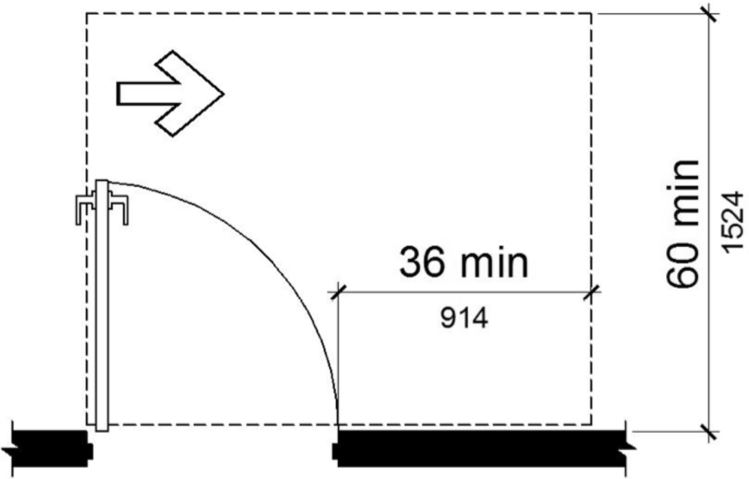
44 inches (1118 mm)2 [2010 ADA Standards] 42 inches, add 6 inches if closer and latch provided |
22 inches (559 mm)3 |
|
From latch side |
Pull |
60 inches (1524 mm) [2010 ADA Standards] 48 inches, add 6" if closer provided |
24 inches (610 mm) |
|
From latch side |
Push |
44 inches (1118 mm)4 [2010 ADA Standards] 42 inches, add 6" if closer provided |
24 inches (610 mm) |
1. Add 12 inches (305 mm) if closer and latch are provided.
2. Add 4 inches (102 mm) if closer and latch are provided.
3. Beyond hinge side.
4. Add 4 inches (102 mm) if closer is provided.
5. Add 6 inches (152 mm) at exterior side of exterior doors.
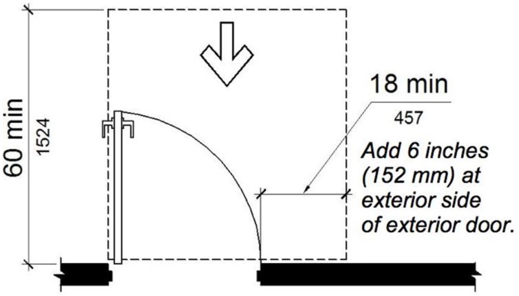
(a) front approach, pull side
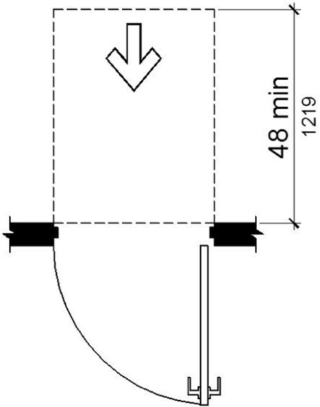
(b) front approach, push side
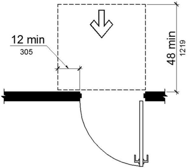
(c) front approach, push side, door provided with both closer and latch
(d) hinge approach, pull side

(e) reserved
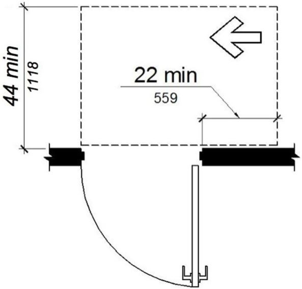
f) hinge approach, push side
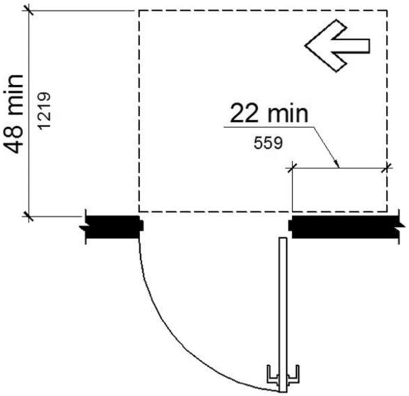
(g) hinge approach, push side, door provided with both closer and latch
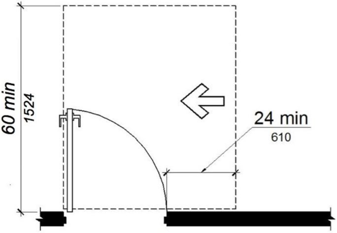
(h) latch approach, pull side

(i) reserved
(j) latch approach, push side
(k) latch approach, push side, door provided with closer
FIGURE 11B-404.2.4.1 MANEUVERING CLEARANCES AT MANUAL SWINGING DOORS AND GATES ‡‡
11B-404.2.4.2 Doorways without doors or gates, sliding doors, and folding doors.
Doorways less than 36 inches (914 mm) wide without doors or gates, sliding doors, or folding doors shall have maneuvering clearances complying with Table 11B-404.2.4.2.
TABLE 11B-404.2.4.2 MANEUVERING CLEARANCES AT DOORWAYS WITHOUT DOORS OR GATES, MANUAL SLIDING DOORS, AND MANUAL FOLDING DOORS
|
MINIMUM MANEUVERING CLEARANCE |
||
|---|---|---|
|
Approach direction |
Perpendicular to doorway |
Parallel to doorway (beyond stop/latch side unless noted) |
|
From Front |
48 inches (1219 mm) |
0 inches (0 mm) |
|
From side1 |
42 inches (1067 mm) |
0 inches (0 mm) |
|
From pocket/hinge side |
42 inches (1067 mm) |
22 inches (559 mm)2 |
|
From stop/latch side |
42 inches (1067 mm) |
24 inches (610 mm) |
1. Doorway with no door only.
2. Beyond pocket/hinge side.
(a) front approach
(b) side approach
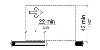
(c) pocket or hinge approach
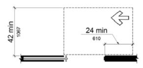
(d) stop or latch approach
FIGURE 11B-404.2.4.2 MANEUVERING CLEARANCES AT DOORWAYS WITHOUT DOORS, SLIDING DOORS, GATES, AND FOLDING DOORS
11B-404.2.4.3 Recessed doors and gates.
Maneuvering clearances for forward approach shall be provided when any obstruction within 18 inches (457 mm) of the latch side at an interior doorway, or within 24 inches (610 mm) of the latch side of an exterior doorway, projects more than 8 inches (203 mm) beyond the face of the door, measured perpendicular to the face of the door or gate.
[2010 ADA Standards] 404.2.4.3 Recessed Doors and Gates. Maneuvering clearances for forward approach shall be provided when any obstruction within 18 inches (455 mm) of the latch side of a doorway projects more than 8 inches (205 mm) beyond the face of the door, measured perpendicular to the face of the door or gate.

ETA Editor's Note
CBC latch side clearance at exterior doors is more stringent than the 2010 ADA Standards.
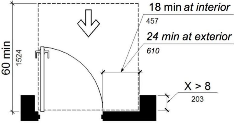
(a) pull side
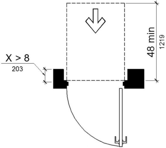
(b) push side
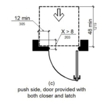
FIGURE 11B-404.2.4.3 MANEUVERING CLEARANCES AT RECESSED DOORS AND GATES ‡‡
11B-404.2.4.4 Floor or ground surface.
Floor or ground surface within required maneuvering clearances shall comply with Section 11B-302. Changes in level, slopes exceeding 1:48, and detectable warnings shall not be permitted.
Exceptions:
11B-404.2.5 Thresholds.
Thresholds, if provided at doorways, shall be ½ inch (12.7 mm) high maximum. Raised thresholds and changes in level at doorways shall comply with Sections 11B-302 and 11B-303.
Exception: Reserved.
[2010 ADA Standards] EXCEPTION: Existing or altered thresholds ¾ inch (19 mm) high maximum that have a beveled edge on each side with a slope not steeper than 1:2 shall not be required to comply with 404.2.5.
11B-404.2.6 Doors in series and gates in series.
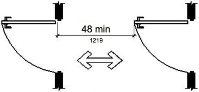
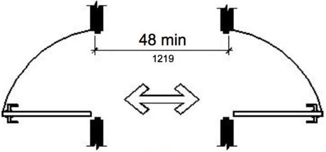
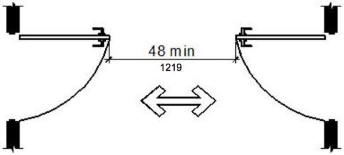
The distance between two hinged or pivoted doors in series and gates in series shall be 48 inches (1219 mm) minimum plus the width of doors or gates swinging into the space.
(a)
(b)
(c)
FIGURE 11B-404.2.6 DOORS IN SERIES AND GATES IN SERIES
11B-404.2.7 Door and gate hardware.
Handles, pulls, latches, locks, and other operable parts on doors and gates shall comply with Section 11B-309.4. Operable parts of such hardware shall be 34 inches (864 mm) minimum and 44 inches (1118 mm) maximum above the finish floor or ground. Where sliding doors are in the fully open position, operating hardware shall be exposed and usable from both sides.
Exceptions:
- Existing locks shall be permitted in any location at existing glazed doors without stiles, existing overhead rolling doors or grilles, and similar existing doors or grilles that are designed with locks that are activated only at the top or bottom rail.
- Access gates in barrier walls and fences protecting pools, spas, and hot tubs shall be permitted to have operable parts of the release of latch on self-latching devices at 54 inches (1372 mm) maximum above the finish floor or ground provided the self-latching devices are not also self-locking devices and operated by means of a key, electronic opener, or integral combination lock.


[2010 ADA Standards] 404.2.7 Door and Gate Hardware. Handles, pulls, latches, locks, and other operable parts on doors and gates shall comply with 309.4. Operable parts of such hardware shall be 34 inches (865 mm) minimum and 48 inches (1220 mm) maximum above the finish floor or ground. Where sliding doors are in the fully open position, operating hardware shall be exposed and usable from both sides.
EXCEPTIONS: 1. Existing locks shall be permitted in any location at existing glazed doors without stiles, existing overhead rolling doors or grilles, and similar existing doors or grilles that are designed with locks that are activated only at the top or bottom rail.
2. Access gates in barrier walls and fences protecting pools, spas, and hot tubs shall be permitted to have operable parts of the release of latch on self-latching devices at 54 inches (1370 mm) maximum above the finish floor or ground provided the self-latching devices are not also self-locking devices and operated by means of a key, electronic opener, or integral combination lock.
11B-404.2.8 Closing speed.
Door and gate closing speed shall comply with Section 11B-404.2.8.
11B-404.2.8.1 Door closers and gate closers.
Door closers and gate closers shall be adjusted so that from an open position of 90 degrees, the time required to move the door to a position of 12 degrees from the latch is 5 seconds minimum.
11B-404.2.8.2 Spring hinges.
Door and gate spring hinges shall be adjusted so that from the open position of 70 degrees, the door or gate shall move to the closed position in 1.5 seconds minimum.
11B-404.2.9 Door and gate opening force.
The force for pushing or pulling open a door or gate shall be as follows:
[2010 ADA Standards] 404.2.9 Door and Gate Opening Force. Fire doors shall have a minimum opening force allowable by the appropriate Administrative Authority. The force for pushing or pulling open a door or gate other than fire doors shall be as follows:
- Interior hinged doors and gates: 5 pounds (22.2 N) maximum.
- Sliding or folding doors: 5 pounds (22 N) maximum.
- Required fire doors: the minimum opening force allowable by the appropriate administrative authority, not to exceed 15 pounds (66.7 N).
- Exterior hinged doors: 5 pounds (22.2 N) maximum.
ETA Editor's Note
The CBC limitation for opening force at non-rated exterior doors is more stringent than the 2010 ADA Standards, and can be difficult to meet without a powered device at exterior doors exposed to wind, or leading from spaces that operate at negative pressure with respect to the exterior environment. That is the principal reason for the preceding Exception to 11B-404.2.9 that does not appear in the 2010 ADA Standards.
These forces do not apply to the force required to retract latch bolts or disengage other devices that hold the door or gate in a closed position.

Exception: When, at a single location, one of every eight exterior door leafs, or fraction of eight, is a powered door, other exterior doors at the same location, serving the same interior space, may have a maximum opening force of 8.5 pounds (37.8 N). The powered leaf(s) shall be located closest to the accessible route.
a. Powered doors shall comply with Section 11B-404.3. Powered doors shall be fully automatic doors complying with Builders Hardware Manufacturers’ Association (BHMA) A156.10 or low energy operated doors complying with BHMA A156.19.
b. Powered doors serving a building or facility with an occupancy of 150 or more shall be provided with a back-up battery or back-up generator. The back-up power source shall be able to cycle the door a minimum of 100 cycles.
c. Powered doors shall be controlled on both the interior and exterior sides of the doors by sensing devices, push plates, vertical actuation bars or other similar operating devices complying with Section 11B-309.
At each location where push plates are provided there shall be two push plates; the centerline of one push plate shall be 7 inches (178 mm) minimum and 8 inches (203 mm) maximum above the floor or ground surface and the centerline of the second push plate shall be 30 inches (762 mm) minimum and 44 inches (1118 mm) maximum above the floor or ground surface. Each push plate shall be a minimum of 4 inches (102 mm) diameter or a minimum of 4 inches by 4 inches (102 mm by 102 mm) square and shall display the International Symbol of Accessibility complying with Section 11B-703.7.
At each location where vertical actuation bars are provided the operable portion shall be located so the bottom is 5 inches (127 mm) maximum above the floor or ground surface and the top is 35 inches (889 mm) minimum above the floor or ground surface. The operable portion of each vertical actuation bar shall be a minimum of 2 inches (51 mm) wide and shall display the International Symbol of Accessibility complying with Section 11B-703.7.
Where push plates, vertical actuation bars or other similar operating devices are provided, they shall be placed in a conspicuous location. A level and clear floor or ground space for forward or parallel approach complying with Section 11B-305 shall be provided, centered on the operating device. Doors shall not swing into the required clear floor or ground space.
d. Signs identifying the accessible entrance required by Section 11B-216.6 shall be placed on, or immediately adjacent to, each powered door. Signs shall be provided in compliance with BHMA A156.10 or BHMA 156.19, as applicable.
e. In addition to the requirements of Item d, where a powered door is provided in buildings or facilities containing assembly occupancies of 300 or more, a sign displaying the International Symbol of Accessibility measuring 6 inches by 6 inches (152 mm by 152 mm), complying with Section 11B-703.7, shall be provided above the door on both the interior and exterior sides of each powered door.
11B-404.2.10 Door and gate surfaces.
Swinging door and gate surfaces within 10 inches (254 mm) of the finish floor or ground measured vertically shall have a smooth surface on the push side extending the full width of the door or gate. Parts creating horizontal or vertical joints in these surfaces shall be within 1/16 inch (1.6 mm) of the same plane as the other and be free of sharp or abrasive edges. Cavities created by added kick plates shall be capped.
Exceptions:
- Sliding doors shall not be required to comply with Section 11B-404.2.10.
- Tempered glass doors without stiles and having a bottom rail or shoe with the top leading edge tapered at 60 degrees minimum from the horizontal shall not be required to meet the 10 inch (254 mm) bottom smooth surface height requirement.
- Doors and gates that do not extend to within 10 inches (254 mm) of the finish floor or ground shall not be required to comply with Section 11B-404.2.10.
- Reserved.
[2010 ADA Standards] 4. Existing doors and gates without smooth surfaces within 10 inches (255 mm) of the finish floor or ground shall not be required to provide smooth surfaces complying with 404.2.10 provided that if added kick plates are installed, cavities created by such kick plates are capped.
ETA Editor's Note
Lacking Exception 4 at 11B-404.2.10, CBC is more stringent at existing doors than 2010 ADA Standards.
11B-404.2.11 Vision lights.
Doors, gates, and side lights adjacent to doors or gates, containing one or more glazing panels that permit viewing through the panels shall have the bottom of at least one glazed panel located 43 inches (1092 mm) maximum above the finish floor.
Exception: Glazing panels with the lowest part more than 66 inches (1676 mm) from the finish floor or ground shall not be required to comply with Section 11B-404.2.11.
ETA Editor's Note
The vision light requirement of CBC 11B-404.2.11 is derived from the 2010 ADA Standards 404.2.11. Under ADA, an existing door with a noncompliant vision light is a Safe Harbored element for path of travel and barrier removal purposes but will have to comply when the door is replaced, and may not be relocated elsewhere on an accessible route. Under CBC, an existing primary entrance door with a noncompliant vision light is not Safe Harbored, unless the Exception at 11B-404.2.11 applies, and must be mitigated under path of travel obligations.
11B-404.3 Automatic and power-assisted doors and gates.
Automatic doors and automatic gates shall comply with Section 11B-404.3. Full-powered automatic doors shall comply with ANSI/BHMA A156.10. Low-energy and power-assisted doors shall comply with ANSI/BHMA A156.19.

11B-404.3.1 Clear width.
Doorways shall provide a clear opening of 32 inches (813 mm) minimum in power-on and power-off mode. The minimum clear width for automatic door systems in a doorway shall provide a clear, unobstructed opening of 32 inches (813 mm) with one leaf positioned at an angle of 90 degrees from its closed position.
[2010 ADA Standards] 404.3.1 Clear Width. Doorways shall provide a clear opening of 32 inches (815 mm) minimum in power-on and power-off mode. The minimum clear width for automatic door systems in a doorway shall be based on the clear opening provided by all leaves in the open position.
ETA Editor's Note
CBC clear width requirement is more stringent at multi-leaf automatic and power-assisted doors than 2010 ADA Standards, since it must be provided by one door leaf.
11B-404.3.2 Maneuvering clearance.
Clearances at power-assisted doors and gates shall comply with Section 11B-404.2.4. Clearances at automatic doors and gates without standby power and serving an accessible means of egress shall comply with Section 11B-404.2.4.
Exception: Where automatic doors and gates remain open in the power-off condition, compliance with Section 11B-404.2.4 shall not be required.
ETA Editor's Note
The implication of 11B-404.3.2 is that power-assist devices (ANSI/BHMA A156.19) cannot substitute for required door maneuvering clearances, even if standby power is provided. Automatic door operators (ANSI/BHMA A156.10) can substitute for required door maneuvering clearances under one of the following conditions: a) standby power is provided; or, b) the door or gate remains open during power failure or cessation. See also DSA Advisory 11B-404.3.
11B-404.3.3 Thresholds.
Thresholds and changes in level at doorways shall comply with Section 11B-404.2.5.
11B-404.3.4 Doors in series and gates in series.
Doors in series and gates in series shall comply with Section 11B-404.2.6.
11B-404.3.5 Controls.
Manually operated controls shall comply with Section 11B-309. The clear floor space adjacent to the control shall be located beyond the arc of the door swing.

11B-404.3.6 Break out opening.
Where doors and gates without standby power are a part of a means of egress, the clear break out opening at swinging or sliding doors and gates shall be 32 inches (813 mm) minimum when operated in emergency mode.
Exception: Where manual swinging doors and gates comply with Section 11B-404.2 and serve the same means of egress compliance with Section 11B-404.3.6 shall not be required.
11B-404.3.7 Revolving doors, revolving gates, and turnstiles.
Revolving doors, revolving gates, and turnstiles shall not be part of an accessible route.
11B-405.1 General.
Ramps on accessible routes shall comply with Section 11B-405.
Exception: In assembly areas, aisle ramps adjacent to seating and not serving elements required to be on an accessible route shall not be required to comply with Section 11B-405.
11B-405.2 Slope.
Ramp runs shall have a running slope not steeper than 1:12.
Exception: Reserved.
[2010 ADA Standards] EXCEPTION: In existing sites, buildings, and facilities, ramps shall be permitted to have running slopes steeper than 1:12 complying with Table 405.2 where such slopes are necessary due to space limitations.
Table 405.2 Maximum Ramp Slope and Rise for Existing Sites, Buildings, and Facilities
|
Slope1 |
Maximum Rise |
|---|---|
|
Steeper than 1:10 but |
3 inches (75 mm) |
|
Steeper than 1:12 but |
6 inches (150 mm) |
1. A slope steeper than 1:8 is prohibited.

ETA Editor's Note
Lacking the Exception at 11B-405.2, CBC is more stringent at existing ramps than 2010 ADA Standards.
11B-405.3 Cross slope.
Cross slope of ramp runs shall not be steeper than 1:48.


11B-405.4 Floor or ground surfaces.
Floor or ground surfaces of ramp runs shall comply with Section 11B-302. Changes in level other than the running slope and cross slope are not permitted on ramp runs.
11B-405.5 Clear width.
The clear width of a ramp run shall be 48 inches (1219 mm) minimum.
Exceptions:
- Within employee work areas, the required clear width of ramps that are a part of common use circulation paths shall be permitted to be decreased by work area equipment provided that the decrease is essential to the function of the work being performed.
- Handrails may project into the required clear width of the ramp at each side 3½ inches (89 mm) maximum at the handrail height.
- The clear width of ramps in residential uses serving an occupant load of fifty or less shall be 36 inches (914 mm) minimum between handrails.
[2010 ADA Standards] 405.5 Clear Width. The clear width of a ramp run and, where handrails are provided, the clear width between handrails shall be 36 inches (915 mm) minimum.
EXCEPTION: Within employee work areas, the required clear width of ramps that are a part of common use circulation paths shall be permitted to be decreased by work area equipment provided that the decrease is essential to the function of the work being performed.
ETA Editor's Note
CBC is more stringent regarding ramp width than 2010 ADA Standards.
11B-405.6 Rise.
The rise for any ramp run shall be 30 inches (762 mm) maximum.
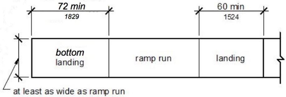
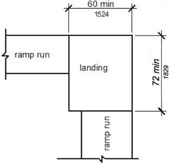
11B-405.7 Landings.
Ramps shall have landings at the top and the bottom of each ramp run. Landings shall comply with Section 11B-405.7.

(a) straight
(b) change in direction
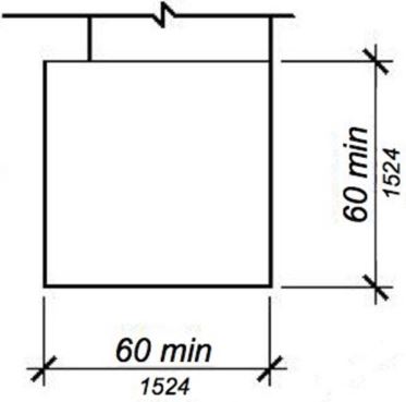
(c) top landing
FIGURE 11B-405.7 RAMP LANDINGS ‡‡
11B-405.7.1 Slope.
Landings shall comply with Section 11B-302. Changes in level, slopes exceeding 1:48, and detectable warnings shall not be permitted.
Exception: Reserved.
11B-405.7.2 Width.
The landing clear width shall be at least as wide as the widest ramp run leading to the landing.
11B-405.7.2.1.
Top landings shall be 60 inches (1524 mm) wide minimum.

11B-405.7.3 Length.
The landing clear length shall be 60 inches (1524 mm) long minimum.
11B-405.7.3.1.
Bottom landings shall extend 72 inches (1829 mm) minimum in the direction of ramp run.
11B-405.7.4 Change in direction.
Ramps that change direction between runs at landings shall have a clear landing 60 inches (1525 mm) minimum by 72 inches (1829 mm) minimum in the direction of downward travel from the upper ramp run.
[2010 ADA Standards] 405.7.4 Change in Direction. Ramps that change direction between runs at landings shall have a clear landing 60 inches (1525 mm) minimum by 60 inches (1525 mm) minimum.
11B-405.7.5 Doorways.
Where doorways are located adjacent to a ramp landing, maneuvering clearances required by Sections 11B-404.2.4 and 11B-404.3.2 shall be permitted to overlap the required landing area. Doors, when fully open, shall not reduce the required ramp landing width by more than 3 inches (76 mm). Doors, in any position, shall not reduce the minimum dimension of the ramp landing to less than 42 inches (1067 mm).
[2010 ADA Standards] 405.7.5 Doorways. Where doorways are located adjacent to a ramp landing, maneuvering clearances required by 404.2.4 and 404.3.2 shall be permitted to overlap the required landing area.

ETA Editor's Note
Since the 2010 ADA Standards makes no distinction between top, bottom, and intermediate landings, CBC is more stringent regarding ramp landings. Also, CBC allows less encroachment of doors onto ramp landings.
11B-405.8 Handrails.
Ramp runs shall have handrails complying with Section 11B-505.
[2010 ADA Standards] 405.8 Handrails. Ramp runs with a rise greater than 6 inches (150 mm) shall have handrails complying with 505.
Exceptions:
- Reserved.
- Reserved.
- Curb ramps do not require handrails.
- At door landings, handrails are not required on ramp runs less than 6 inches (152 mm) in rise or 72 inches (1829 mm) in length.
[2010 ADA Standards] EXCEPTION: Within employee work areas, handrails shall not be required where ramps that are part of common use circulation paths are designed to permit the installation of handrails complying with 505. Ramps not subject to the exception to 405.5 shall be designed to maintain a 36 inch (915 mm) minimum clear width when handrails are installed.
ETA Editor's Note
Since CBC lacks the Exception at employee work areas, and since it requires handrails at short ramps that are not curb ramps, CBC is more stringent regarding ramp handrails than 2010 ADA Standards.
11B-405.9 Edge protection.
Edge protection complying with Section 11B-405.9.2 shall be provided on each side of ramp runs and at each side of ramp landings.
[2010 ADA Standards] 405.9 Edge Protection. Edge protection complying with 405.9.1 or 405.9.2 shall be provided on each side of ramp runs and at each side of ramp landings.
Exceptions:
- Edge protection shall not be required on ramps that are not required to have handrails and have sides complying with Section 11B-406.2.2.
- Edge protection shall not be required on the sides of ramp landings serving an adjoining ramp run or stairway.
- Edge protection shall not be required on the sides of ramp landings having a vertical drop-off of ½ inch (12.7 mm) maximum within 10 inches (254 mm) horizontally of the minimum landing area specified in Section 11B-405.7.
11B-405.9.1 Reserved.
[2010 ADA Standards] 405.9.1 Extended Floor or Ground Surface. The floor or ground surface of the ramp run or landing shall extend 12 inches (305 mm) minimum beyond the inside face of a handrail complying with 505.
[2010 ADA Standards] Advisory 405.9.1 Extended Floor or Ground Surface. The extended surface prevents wheelchair casters and crutch tips from slipping off the ramp surface.
11B-405.9.2 Curb or barrier.
A curb or barrier shall be provided that prevents the passage of a 4-inch (102 mm) diameter sphere, where any portion of the sphere is within 4 inches (102 mm) of the finish floor or ground surface. To prevent wheel entrapment, the curb or barrier shall provide a continuous and uninterrupted barrier along the length of the ramp. [Safe Harbor 11B-405.9.2]
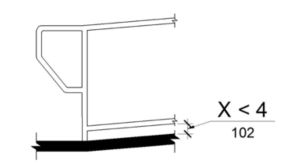
CURB OR BARRIER EDGE PROTECTION
ETA Editor's Note
CBC requires either a curb or a barrier for edge protection at ramps, and does not recognize the extended floor or ground surface also permitted by 2010 ADA Standards.
11B-405.10 Wet conditions.
Landings subject to wet conditions shall be designed to prevent the accumulation of water.
11B-406 Curb ramps, blended transitions and islands
[2010 ADA Standards] 406 Curb Ramps
ETA Editor's Note
11B-406.1 General.
Curb ramps, blended transitions and islands on accessible routes shall comply with Section 11B-406. Curb ramps may be perpendicular, parallel, or a combination of perpendicular and parallel.
[2010 ADA Standards] 406.1 General. Curb ramps on accessible routes shall comply with 406, 405.2 through 405.5, and 405.10.
11B-406.2 Perpendicular curb ramps.
Perpendicular curb ramps shall comply with Sections 11B-406.2 and 11B-406.5.
11B-406.2.1 Slope.
Ramp runs shall have a running slope not steeper than 1:12.
11B-406.2.2 Sides of curb ramps.
Where provided, curb ramp flares shall not be steeper than 1:10.
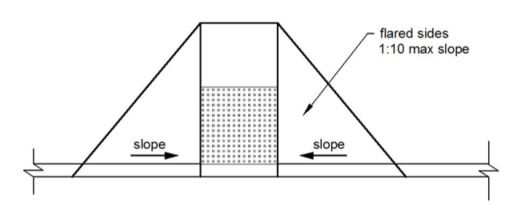
FIGURE 11B-406.2.2 SIDES OF CURB RAMPS ‡‡
11B-406.3 Parallel curb ramps.
Parallel curb ramps shall comply with Sections 11B-406.3 and 11B-406.5. A parallel curb ramp may be provided with one sloping segment or two opposing sloping segments.
11B-406.3.1 Slope.
The running slope of the curb ramp segments shall be in-line with the direction of sidewalk travel. Ramp runs shall have a running slope not steeper than 1:12.
11B-406.3.2 Turning space.
A turning space 48 inches (1219 mm) minimum by 48 inches (1219 mm) minimum shall be provided at the bottom of the curb ramp. The slope of the turning space in all directions shall be 1:48 maximum.
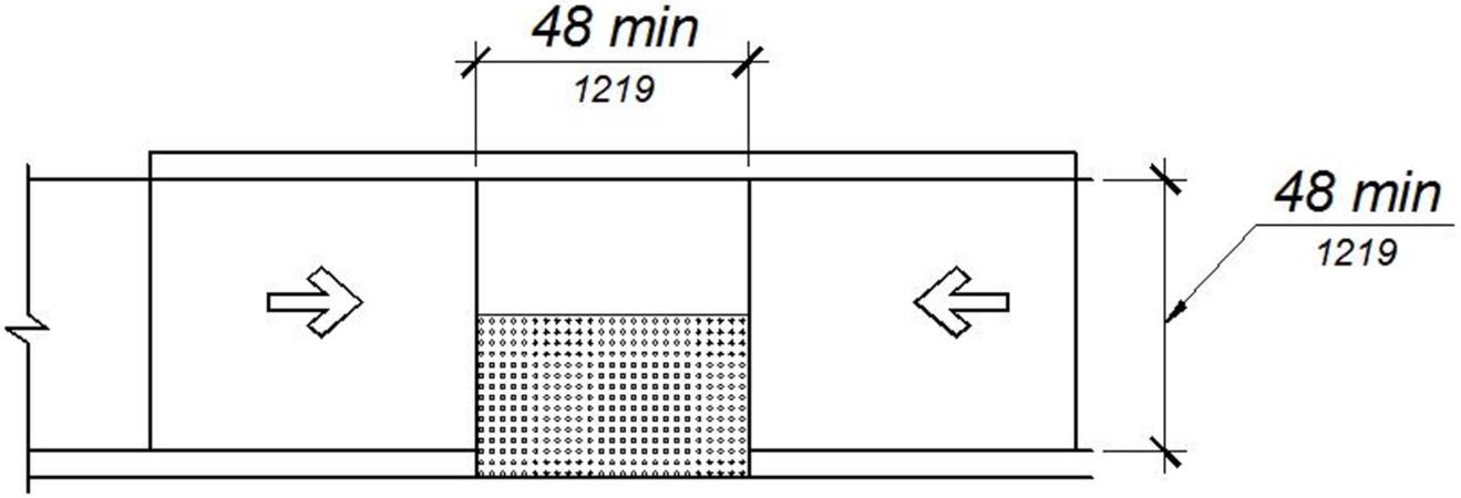
FIGURE 11B-406.3.2 PARALLEL CURB RAMPS ‡‡
11B-406.4 Blended transitions.
Blended transitions shall comply with Sections 11B-406.4 and 11B-406.5.
11B-406.4.1 Slope.
Blended transitions shall have a running slope not steeper than 1:20.
11B-406.5 Common requirements.
Curb ramps and blended transitions shall comply with Section 11B-406.5.
11B-406.5.1 Location.
Curb ramps and the flared sides of curb ramps shall be located so that they do not project into vehicular traffic lanes, parking spaces, or parking access aisles. Curb ramps at marked crossings shall be wholly contained within the markings, excluding any flared sides.
Exception: Diagonal curb ramps shall comply with Section 11B-406.5.9.
11B-406.5.2 Width.
The clear width of curb ramp runs (excluding any flared sides), blended transitions, and turning spaces shall be 48 inches (1219 mm) minimum.
11B-406.5.3 Landings.
Landings shall be provided at the tops of curb ramps and blended transitions. The landing clear length shall be 48 inches (1219 mm) minimum. The landing clear width shall be at least as wide as the curb ramp, excluding any flared sides, or the blended transition leading to the landing. The slope of the landing in all directions shall be 1:48 maximum.
[2010 ADA Standards] 406.4 Landings. Landings shall be provided at the tops of curb ramps. The landing clear length shall be 36 inches (915 mm) minimum. The landing clear width shall be at least as wide as the curb ramp, excluding flared sides, leading to the landing.
Exception: Parallel curb ramps shall not be required to comply with Section 11B-406.5.3.
[2010 ADA Standards] EXCEPTION: In alterations, where there is no landing at the top of curb ramps, curb ramp flares shall be provided and shall not be steeper than 1:12.

Some designs have been proposed that reduce or omit the level top landing by providing a curb ramp with flared sides of 1:12 or less. This design is not compliant with the building code and may result in a condition where a wheelchair user cannot safely turn and proceed along the intersecting walk. Section 11B-403.5.1.1, requires walks and sidewalks to be 48” wide minimum; Section 11B-403.3 requires walks and sidewalks to have a cross-slope of 1:48 or less. In this example, reducing or omitting the top landing of the curb ramp may result in a substandard walk width and/or a walk with a cross-slope in excess of 1:48. ◼
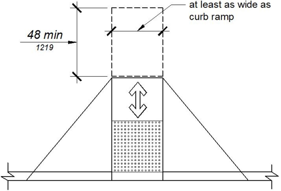
FIGURE 11B-406.5.3 LANDINGS AT THE TOP OF CURB RAMPS ‡‡
11B-406.5.4 Floor or ground surfaces.
Floor or ground surfaces of curb ramps and blended transitions shall comply with Section 11B-405.4.
11B-406.5.5 Wet conditions.
Curb ramps and blended transitions shall comply with Section 11B-405.10.
11B-406.5.6 Grade breaks.
Grade breaks at the top and bottom of curb ramp runs shall be perpendicular to the direction of the ramp run. Grade breaks shall not be permitted on the surface of ramp runs and turning spaces. Surface slopes that meet at grade breaks shall be flush.
11B-406.5.7 Cross slope.
The cross slope of curb ramps and blended transitions shall be 1:48 maximum.
11B-406.5.8 Counter slope.
Counter slopes of adjoining gutters and road surfaces immediately adjacent to and within 24 inches (610 mm) of the curb ramp shall not be steeper than 1:20. The adjacent surfaces at transitions at curb ramps to walks, gutters, and streets shall be at the same level.
[2010 ADA Standards] 406.2 Counter Slope. Counter slopes of adjoining gutters and road surfaces immediately adjacent to the curb ramp shall not be steeper than 1:20. The adjacent surfaces at transitions at curb ramps to walks, gutters, and streets shall be at the same level.
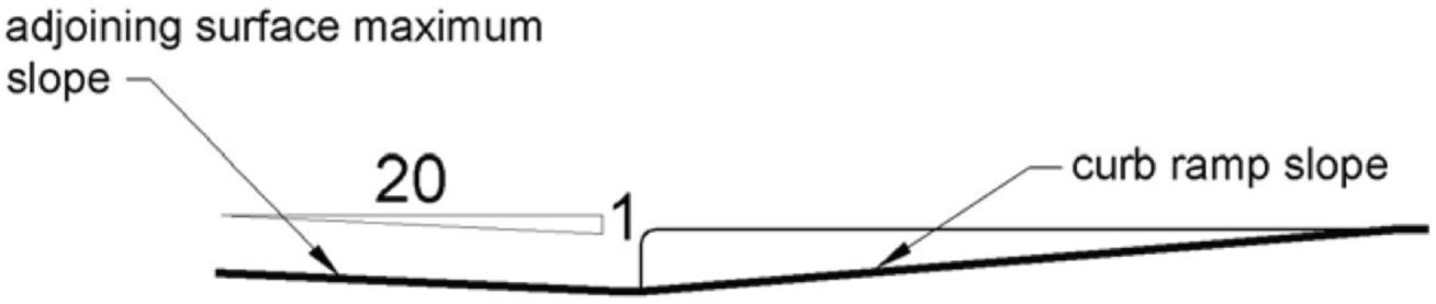
FIGURE 11B-406.5.8 COUNTER SLOPE OF SURFACES ADJACENT TO CURB RAMPS
11B-406.5.9 Clear space at diagonal curb ramps.
The bottom of diagonal curb ramps shall have a clear space 48 inches (1219 mm) minimum outside active traffic lanes of the roadway. Diagonal curb ramps provided at marked crossings shall provide the 48 inches (1219 mm) minimum clear space within the markings.
11B-406.5.10 Diagonal curb ramps.
Diagonal or corner type curb ramps are perpendicular or parallel curb ramps that are oriented diagonally at an intersection. Diagonal or corner type curb ramps with returned curbs or other well-defined edges shall have the edges parallel to the direction of pedestrian flow. Diagonal curb ramps with flared sides shall have a segment of curb 24 inches (610 mm) long minimum located on each side of the curb ramp and within the marked crossing.
[2010 ADA Standards] 406.6 Diagonal Curb Ramps. Diagonal or corner type curb ramps with returned curbs or other well-defined edges shall have the edges parallel to the direction of pedestrian flow. The bottom of diagonal curb ramps shall have a clear space 48 inches (1220 mm) minimum outside active traffic lanes of the roadway. Diagonal curb ramps provided at marked crossings shall provide the 48 inches (1220 mm) minimum clear space within the markings. Diagonal curb ramps with flared sides shall have a segment of curb 24 inches (610 mm) long minimum located on each side of the curb ramp and within the marked crossing.
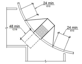
FIGURE 11B-406.5.10 DIAGONAL OR CORNER TYPE CURB RAMPS ‡‡
11B-406.5.12 Detectable warnings
Curb ramps and blended transitions shall have detectable warnings complying with Section 11B-705.
U.S. Access Board's Note to Reader:
The Department of Transportation's ADA Standards require detectable warnings on curb ramps:
[ADA Title II - Public Transportation] 406.8 Detectable Warnings. A curb ramp shall have a detectable warning complying with 705. The detectable warning shall extend the full width of the curb ramp (exclusive of flared sides) and shall extend either the full depth of the curb ramp or 24 inches (610 mm) deep minimum measured from the back of the curb on the ramp surface.
11B-406.6 Islands.
Raised islands in crossings shall be cut through level with the street or have curb ramps at both sides. The clear width of the accessible route at islands shall be 60 inches (1524 mm) wide minimum. Where curb ramps are provided, they shall comply with Section 11B-406. Landings complying with Section 11B-406.5.3 and the accessible route shall be permitted to overlap. Islands shall have detectable warnings complying with Section 11B-705.
[2010 ADA Standards] 406.7 Islands. Raised islands in crossings shall be cut through level with the street or have curb ramps at both sides. Each curb ramp shall have a level area 48 inches (1220 mm) long minimum by 36 inches (915 mm) wide minimum at the top of the curb ramp in the part of the island intersected by the crossings. Each 48 inch (1220 mm) minimum by 36 inch (915 mm) minimum area shall be oriented so that the 48 inch (1220 mm) minimum length is in the direction of the running slope of the curb ramp it serves. The 48 inch (1220 mm) minimum by 36 inch (915 mm) minimum areas and the accessible route shall be permitted to overlap.
(a) cut through at island
(b) curb ramp at island
FIGURE 11B-406.6 ISLANDS IN CROSSINGS ‡‡
11B-407.1 General.
Elevators shall comply with Section 11B-407 and with ASME A17.1. They shall be passenger elevators as classified by ASME A17.1. Elevator operation shall be automatic.


DSA regulates the usability of elevators and platform (wheelchair) lifts for persons with disabilities. Accessibility scoping requirements for elevators and lifts are located in Sections 11B-206.6 and 11B-206.7; technical requirements are located in Sections 11B-407, 11B-408, 11B-409 and 11B-410. ◼
11B-407.1.1 Combined passenger and freight elevators.
When the only elevators provided for use by the public and employees are combination passenger and freight elevators, they shall comply with Section 11B-407 and with ASME A17.1.
11B-407.2.1 Call controls.
Where elevator call buttons or keypads are provided, they shall comply with Sections 11B-407.2.1 and 11B-309.4.
[2010 ADA Standards] 407.2.1 Call Controls. Where elevator call buttons or keypads are provided, they shall comply with 407.2.1 and 309.4. Call buttons shall be raised or flush.
Exception: Reserved.
[2010 ADA Standards] EXCEPTION: Existing elevators shall be permitted to have recessed call buttons.
11B-407.2.1.1 Height.
Call buttons and keypads shall be located within one of the reach ranges specified in Section 11B-308, measured to the centerline of the highest operable part.
Exception: Reserved.
[2010 ADA Standards] EXCEPTION: Existing call buttons and existing keypads shall be permitted to be located at 54 inches (1370 mm) maximum above the finish floor, measured to the centerline of the highest operable part.
11B-407.2.1.2 Size and shape.
Call buttons shall have square shoulders, be ¾ inch (19.1 mm) minimum in the smallest dimension and shall be raised 1/8 inch (3.2 mm) plus or minus 1/32 inch (0.8 mm) above the surrounding surface. The buttons shall be activated by a mechanical motion that is detectable.
[2010 ADA Standards] 407.2.1.2 Size. Call buttons shall be ¾ inch (19 mm) minimum in the smallest dimension.
Exception: Reserved.
[2010 ADA Standards] EXCEPTION: Existing elevator call buttons shall not be required to comply with 407.2.1.2.
11B-407.2.1.3 Clear floor or ground space.
A clear floor or ground space complying with Section 11B-305 shall be provided at call controls.

11B-407.2.1.4 Location.
The call button that designates the up direction shall be located above the call button that designates the down direction.
Exception: Reserved.
[2010 ADA Standards] 407.2.1.4 Location. Destination-oriented elevators shall not be required to comply with 407.2.1.4.

11B-407.2.1.5 Signals.
Call buttons shall have visible signals that will activate when each call is registered and will extinguish when each call is answered. Call buttons shall be internally illuminated with a white light over the entire surface of the button.
[2010 ADA Standards] 407.2.1.5 Signals. Call buttons shall have visible signals to indicate when each call is registered and when each call is answered.
Exceptions:
- Reserved.
- Reserved.
[2010 ADA Standards] 2. Existing elevators shall not be required to comply with 407.2.1.5.
11B-407.2.1.6 Keypads.
Where keypads are provided, keypads shall be in a standard telephone keypad arrangement and shall comply with Section 11B-407.4.7.2.
ETA Editor's Note
Lacking certain Exceptions allowed by 2010 ADA Standards, and imposing additional requirements regarding call buttons, the preceding CBC requirements pertaining to elevator call controls are more stringent than 2010 ADA Standards.
11B-407.2.2 Hall signals.
Hall signals, including in-car signals, shall comply with Section 11B-407.2.2.
11B-407.2.2.1 Visible and audible signals.
A visible and audible signal shall be provided at each hoistway entrance to indicate which car is answering a call and the car’s direction of travel. Where in-car signals are provided, they shall be visible from the floor area adjacent to the hall call buttons.
Exceptions:
- Reserved.
- Reserved.
[2010 ADA Standards] 2. In existing elevators, a signal indicating the direction of car travel shall not be required.
11B-407.2.2.2 Visible signals.
Visible signal fixtures shall be centered at 72 inches (1829 mm) minimum above the finish floor or ground. The visible signal elements shall be a minimum 2½ inches (64 mm) high by 2½ inches (64 mm) wide. Signals shall be visible from the floor area adjacent to the hall call button.
Exceptions:
- Reserved.
- Reserved.
[2010 ADA Standards] 2. Existing elevators shall not be required to comply with 407.2.2.2.
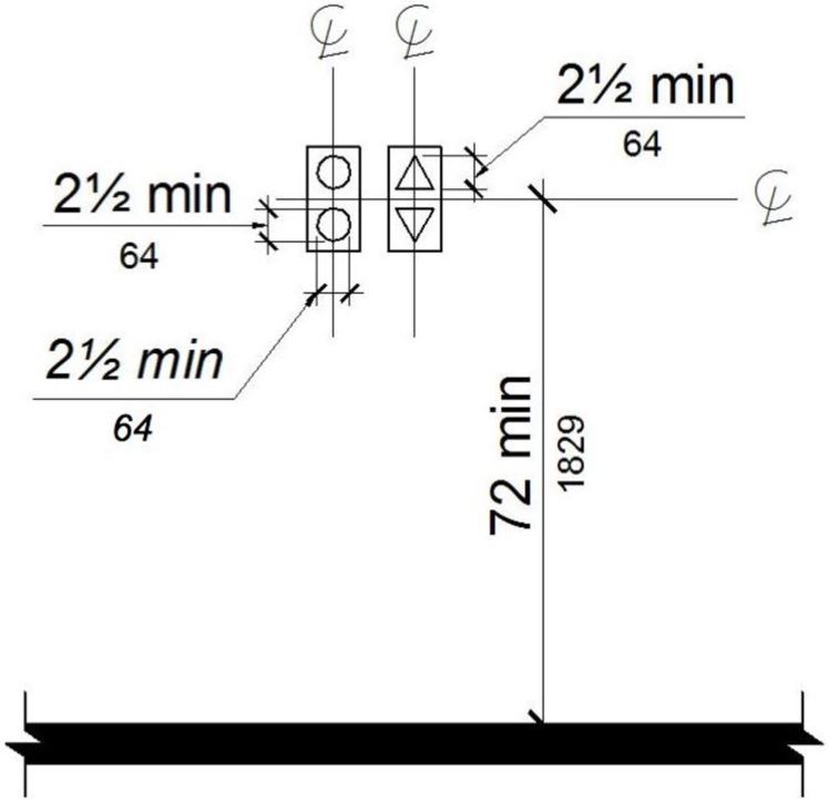
FIGURE 11B-407.2.2.2 VISIBLE HALL SIGNALS ‡‡
11B-407.2.2.3 Audible signals.
Audible signals shall sound once for the up direction and twice for the down direction, or shall have verbal annunciators that indicate the direction of elevator car travel. Audible signals shall have a frequency of 1500 Hz maximum. Verbal annunciators shall have a frequency of 300 Hz minimum and 3000 Hz maximum. The audible signal and verbal annunciator shall be 10 dB minimum above ambient, but shall not exceed 80 dB, measured at the hall call button.
Exceptions:
- Reserved.
- Reserved.
[2010 ADA Standards] 2. Existing elevators shall not be required to comply with the requirements for frequency and dB range of audible signals.
11B-407.2.2.4 Reserved.
ETA Editor's Note
Lacking certain Exceptions allowed by 2010 ADA Standards, and imposing additional requirements regarding visible signals, the preceding CBC requirements pertaining to elevator hall signals are more stringent than 2010 ADA Standards.
11B-407.2.3 Hoistway signs.
Signs at elevator hoistways shall comply with Section 11B-407.2.3.
11B-407.2.3.1 Floor designation.
Floor designations complying with Sections 11B-703.2 and 11B-703.4.1 shall be provided on both jambs of elevator hoistway entrances. Floor designations shall be provided in both raised characters and Braille. Raised characters shall be 2 inches (51 mm) high. A raised star, placed to the left of the floor designation, shall be provided on both jambs at the main entry level. The outside diameter of the star shall be 2 inches (51 mm) and all points shall be of equal length. Raised characters, including the star, shall be white on a black background. Braille complying with Section 11B-703.3 shall be placed below the corresponding raised characters and the star. The Braille translation for the star shall be “MAIN”. Applied plates are acceptable if they are permanently fixed to the jamb.
[2010 ADA Standards] 407.2.3.1 Floor Designation. Floor designations complying with 703.2 and 703.4.1 shall be provided on both jambs of elevator hoistway entrances. Floor designations shall be provided in both tactile characters and braille. Tactile characters shall be 2 inches (51 mm) high minimum. A tactile star shall be provided on both jambs at the main entry level.
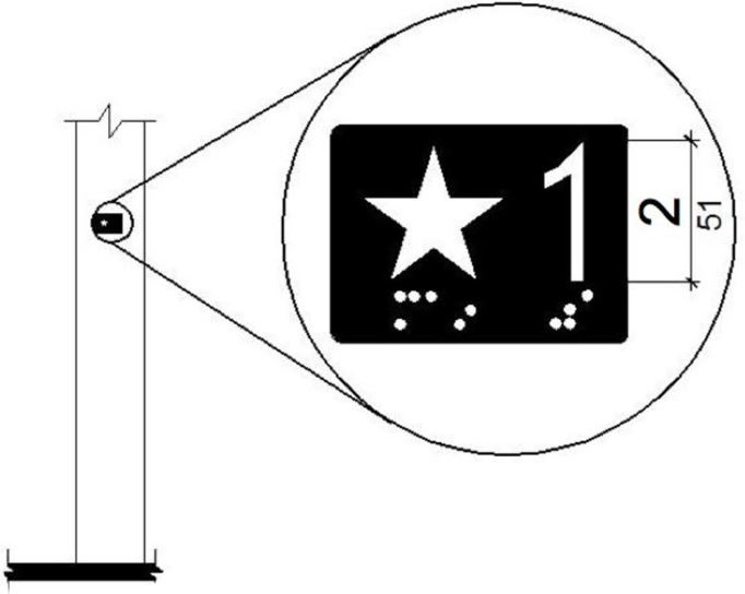
FIGURE 11B-407.2.3.1 FLOOR DESIGNATIONS ON JAMBS OF ELEVATOR HOISTWAY ENTRANCES ‡‡
11B-407.2.3.2 Reserved.
ETA Editor's Note
Imposing additional requirements regarding characters and colors, the preceding CBC requirements pertaining to elevator hoistway signs are more stringent than 2010 ADA Standards.
11B-407.3 Elevator door requirements.
Hoistway and car doors shall comply with Section 11B-407.3.
11B-407.3.1 Type.
Elevator doors shall be the horizontal sliding type. Car gates shall be prohibited.
11B-407.3.2 Operation.
Elevator hoistway and car doors shall open and close automatically.
Exception: Existing manually operated hoistway swing doors shall be permitted provided that they comply with Sections 11B-404.2.3 and 11B-404.2.9. Car door closing shall not be initiated until the hoistway door is closed.
11B-407.3.3 Reopening device.
Elevator doors shall be provided with a reopening device complying with Section 11B-407.3.3 that shall stop and reopen a car door and hoistway door automatically if the door becomes obstructed by an object or person.
Exception: Existing elevators with manually operated doors shall not be required to comply with Section 11B-407.3.3.
11B-407.3.3.1 Height.
The device shall be activated by sensing an obstruction passing through the opening at 5 inches (127 mm) nominal and 29 inches (737 mm) nominal above the finish floor.
11B-407.3.3.2 Contact.
The device shall not require physical contact to be activated, although contact is permitted to occur before the door reverses.
11B-407.3.3.3 Duration.
Door reopening devices shall remain effective for 20 seconds minimum.
11B-407.3.4 Door and signal timing.
The minimum acceptable time from notification that a car is answering a call until the doors of that car start to close shall be calculated from the following equation:
T = D/(1.5 ft/s) or T = D/(457 mm/s) = 5 seconds minimum where T equals the total time in seconds and D equals the distance (in feet or millimeters) from the point in the lobby or corridor 60 inches (1524 mm) directly in front of the farthest call button controlling that car to the centerline of its hoistway door.
Exceptions:
- For cars with in-car lanterns, T shall be permitted to begin when the signal is visible from the point 60 inches (1524 mm) directly in front of the farthest hall call button and the audible signal is sounded.
- Reserved.
[2010 ADA Standards] 2. Destination-oriented elevators shall not be required to comply with 407.3.4.
11B-407.3.5 Door delay.
Elevator doors shall remain fully open in response to a car call for 5 seconds minimum.
[2010 ADA Standards] 407.3.5 Door Delay. Elevator doors shall remain fully open in response to a car call for 3 seconds minimum.
11B-407.3.6 Width.
The width of elevator doors shall comply with Table 11B-407.4.1.
Exception: In existing elevators, a power-operated car door complying with Section 11B-404.2.3 shall be permitted.
11B-407.4.1 Car dimensions.
Inside dimensions of elevator cars and clear width of elevator doors shall comply with Table 11B-407.4.1.
Exception: In existing buildings, where existing shaft configuration prohibits strict compliance with Section 11B-407.4.1, existing elevator car configurations that provide a clear floor area of 18 square feet (1.67 m2) minimum and also provide an inside clear depth 54 inches (1372 mm) minimum and a clear width 48 inches (1219 mm) minimum shall be permitted.
[2010 ADA Standards] EXCEPTION: Existing elevator car configurations that provide a clear floor area of 16 square feet (1.5 m2) minimum and also provide an inside clear depth 54 inches (1370 mm) minimum and a clear width 36 inches (915 mm) minimum shall be permitted.
ETA Editor's Note
The CBC Exception at 11B-407.4.1 is more stringent than that of 2010 ADA Standards regarding minimum car dimensions for existing elevators.
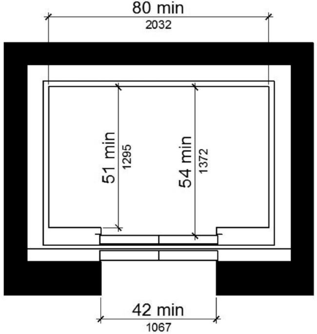
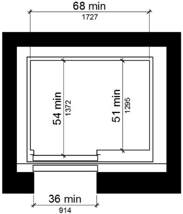
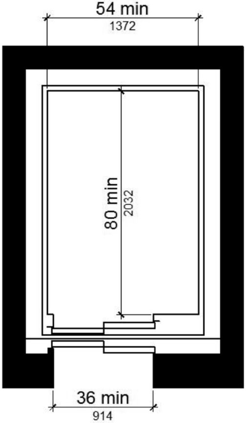
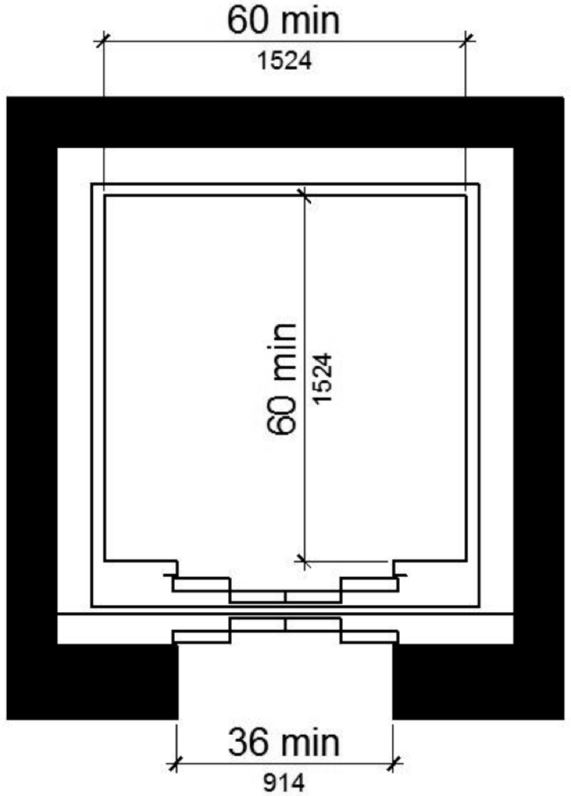
TABLE 11B-407.4.1 ELEVATOR CAR DIMENSIONS
|
MINIMUM DIMENSIONS |
||||
|---|---|---|---|---|
|
Door Location |
Door clear width | Inside car, side to side | Inside car, back wall to front return |
Inside car, back wall to inside face of door |
|
Centered |
42 inches (1067 mm) |
80 inches (2032 mm) |
51 inches (1295 mm) |
54 inches (1372 mm) |
|
Side (off-centered) |
36 inches (914 mm)1 |
68 inches (1727 mm) |
51 inches (1295 mm) |
54 inches (1372 mm) |
|
Any |
36 inches (914 mm)1 |
54 inches (1372 mm) |
80 inches (2032 mm) |
80 inches (2032 mm) |
|
Any |
36 inches (914 mm)2 |
60 inches (1524 mm)2 |
60 inches (1524 mm)2 |
60 inches (1524 mm)2 |
|
1. A tolerance of minus 5/8 inch (15.9 mm) is permitted. 2. Other car configurations that provide a turning space complying with Section 11B-304 with the door closed shall be permitted. |
||||
(a) centered door
(b) side (off-centered) door
(c) any door location
(d) any door location
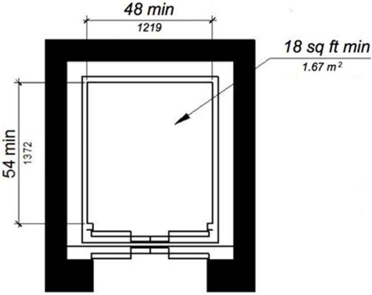
(e) Exception existing elevator car configuration
FIGURE 11B-407.4.1 ELEVATOR CAR DIMENSIONS ‡‡
11B-407.4.2 Floor surfaces.
Floor surfaces in elevator cars shall comply with Section 11B-302 and 11B-303.
11B-407.4.3 Platform to hoistway clearance.
The clearance between the car platform sill and the edge of any hoistway landing shall be 1¼ inch (32 mm) maximum.
11B-407.4.4 Leveling.
Each car shall be equipped with a self-leveling feature that will automatically bring and maintain the car at floor landings within a tolerance of ½ inch (12.7 mm) under rated loading to zero loading conditions.
11B-407.4.5 Illumination.
The level of illumination at the car controls, platform, car threshold and car landing sill shall be 5 foot candles (54 lux) minimum.
11B-407.4.6 Elevator car controls.
Where provided, elevator car controls shall comply with Sections 11B-407.4.6 and 11B-309.4.
Exception: In existing elevators, where a new car operating panel complying with Section 11B-407.4.6 is provided, existing car operating panels may remain operational and shall not be required to comply with Section 11B-407.4.6.
11B-407.4.6.1 Location.
Controls shall be located within one of the reach ranges specified in Section 11B-308.
Exceptions:
- Where the elevator panel serves more than 16 openings and a parallel approach is provided, buttons with floor designations shall be permitted to be 54 inches (1372 mm) maximum above the finish floor.
- In existing elevators, car control buttons with floor designations shall be permitted to be located 54 inches (1372 mm) maximum above the finish floor when a parallel approach is provided.
11B-407.4.6.2 Buttons.
Car control buttons with floor designations shall comply with Section 11B-407.4.6.2.
Exception: Reserved.
[2010 ADA Standards] EXCEPTION: In existing elevators, buttons shall be permitted to be recessed.
11B-407.4.6.2.1 Size and shape. Buttons shall have square shoulders, be ¾ inch (19.1 mm) minimum in their smallest dimension and be raised 1/8 inch (3.2 mm) plus or minus 1/32 inch (0.8 mm) above the surrounding surface.
[2010 ADA Standards] 407.4.6.2.1 Size. Buttons shall be ¾ inch (19 mm) minimum in their smallest dimension.
Buttons shall be arranged with numbers in ascending order. When two or more columns of buttons are provided they shall read from left to right.
Car control buttons shall be illuminated.
Car control buttons shall be activated by a mechanical motion that is detectable.
11B-407.4.6.3 Keypads.
Car control keypads shall be in a standard telephone keypad arrangement and shall comply with Section 11B-407.4.7.2.
11B-407.4.6.4 Emergency controls.
Emergency controls shall comply with Section 11B-407.4.6.4.
Emergency control buttons shall have their centerlines 35 inches (889 mm) minimum above the finish floor.
Emergency controls, including the emergency alarm, shall be grouped at the bottom of the panel.
11B-407.4.7 Designations and indicators of car controls.
Designations and indicators of car controls shall comply with Section 11B-407.4.7.
Exception: In existing elevators, where a new car operating panel complying with Section 11B-407.4.7 is provided, existing car operating panels may remain operational and shall not be required to comply with Section 11B-407.4.7.
11B-407.4.7.1 Buttons.
Car control buttons shall comply with Section 11B-407.4.7.1.
Control buttons shall be identified by raised characters or symbols, white on a black background, complying with Section 11B-703.2 and Braille complying with Section 11B-703.3.
[2010 ADA Standards] 407.4.7.1.1 Type. Control buttons shall be identified by tactile Characters complying with 703.2.
Raised characters or symbols and Braille designations shall be placed immediately to the left of the control button to which the designations apply.
Exception: Reserved.
[2010 ADA Standards] EXCEPTION: Where space on an existing car operating panel precludes tactile markings to the left of the controls, markings shall be placed as near to the control as possible.
The control button for the emergency stop, alarm, door open, door close, main entry floor, and phone, shall be identified with raised symbols and Braille as shown in Table 11B-407.4.7.1.3.
TABLE 11B-407.4.7.1.3 ELEVATOR CONTROL BUTTON IDENTIFICATION
|
Control Button |
Tactile Symbol |
Braille Message |
|
Emergency Stop |
 |
 "ST"OP Three cells |
|
Alarm |
 |
 AL"AR"M Four cells |
|
Door Open |
 |
 OP"EN" Three cells |
|
Door Close |
 |
 CLOSE Five cells |
|
Main Entry Floor |
 |
 MA"IN" Three cells |
|
Phone |
 |
 PH"ONE" Four cells |
11B-407.4.7.1.4 Visible indicators.
Buttons with floor designations shall be provided with visible indicators to show that a call has been registered. The visible indication shall extinguish when the car arrives at the designated floor.
11B-407.4.7.1.5 Button spacing.
A minimum clear space of 3/8 inch (9.5 mm) or other suitable means of separation shall be provided between rows of control buttons.
11B-407.4.7.2 Keypads.
Keypads shall be identified by characters complying with Section 11B-703.5 and shall be centered on the corresponding keypad button. The number five key shall have a single raised dot. The dot shall be 0.118 inch (3 mm) to 0.120 inch (3.05 mm) base diameter and in other aspects comply with Table 11B-703.3.1.
ETA Editor's Note
The preceding CBC requirements for elevator controls at 11B-407.4.6 and 11B-407.4.7 are more stringent than those of 2010 ADA Standards.
11B-407.4.8 Car position indicators.
Audible and visible car position indicators shall be provided in elevator cars.
11B-407.4.8.1 Visible indicators.
Visible indicators shall comply with Section 11B-407.4.8.1.
Characters shall be ½ inch (12.7 mm) high minimum.
Indicators shall be located above the car control panel or above the door.
11B-407.4.8.1.3 Floor arrival.
As the car passes a floor and when a car stops at a floor served by the elevator, the corresponding character shall illuminate.
Exception: Reserved.
[2010 ADA Standards] EXCEPTION: Destination-oriented elevators shall not be required to comply with 407.4.8.1.3 provided that the visible indicators extinguish when the call has been answered.
[2010 ADA Standards] 407.4.8.1.4 Destination Indicator. In destination-oriented elevators, a display shall be provided in the car with visible indicators to show car destinations.
11B-407.4.8.2 Audible indicators.
Audible indicators shall comply with Section 11B-407.4.8.2.
The signal shall be an automatic verbal annunciator which announces the floor at which the car is about to stop.
Exception: For elevators that have a rated speed of 200 feet per minute (1 m/s) or less, a non-verbal audible signal with a frequency of 1500 Hz maximum which sounds as the car passes or is about to stop at a floor served by the elevator shall be permitted.
The verbal annunciator shall be 10 dB minimum above ambient, but shall not exceed 80 dB, measured at the annunciator.
The verbal annunciator shall have a frequency of 300 Hz minimum to 3000 Hz maximum.
11B-407.4.9 Emergency communication.
Emergency two-way communication systems shall comply with Section 11B-308. Raised symbols or characters, white on a black background, and Braille shall be provided adjacent to the device and shall comply with Sections 11B-703.2 and 11B-703.3. Emergency two-way communication systems between the elevator and a point outside the hoistway shall comply with ASME A17.1.
[2010 ADA Standards] 407.4.9 Emergency Communication. Emergency two-way communication systems shall comply with 308. Tactile symbols and Characters shall be provided adjacent to the device and shall comply with 703.2.
11B-407.4.10 Support rail.
Support rails shall be provided on at least one wall of the car.

There is no requirement for support rails inside elevator cars in 2010 ADA Standards.
11B-407.4.10.1 Location.
Clearance between support rails and adjacent surfaces shall be 1½ inches (38 mm) minimum. Top of support rails shall be 31 inches (787 mm) minimum to 33 inches (838 mm) maximum above the floor of the car. The ends of the support rail shall be 6 inches (152 mm) maximum from adjacent walls.
11B-407.4.10.2 Surfaces.
Support rails shall be smooth and any surface adjacent to them shall be free of sharp or abrasive elements.
11B-407.4.10.3 Structural strength.
Allowable stresses shall not be exceeded for materials used when a vertical or horizontal force of 250 pounds (1112 N) is applied at any point on the support rail, fastener, mounting device, or supporting structure.
11B-408.1 General.
Limited-use/limited-application elevators shall comply with Section 11B-408 and with ASME A17.1. They shall be passenger elevators as classified by ASME A17.1. Elevator operation shall be automatic.

DSA regulates the usability of elevators and platform (wheelchair) lifts for persons with disabilities. Accessibility scoping requirements for elevators and lifts are located in Sections 11B-206.6 and 11B-207.6 [sic]; technical requirements are located in Sections 11B-407, 11B-408, 11B-409 and 11B-410. ◼
11B-408.2 Elevator landings.
Landings serving limited-use/limited-application elevators shall comply with Section 11B-408.2.
11B-408.2.1 Call buttons.
Elevator call buttons and keypads shall comply with Section 11B-407.2.1.
11B-408.2.2 Hall signals.
Hall signals shall comply with Section 11B-407.2.2.
11B-408.3 Elevator doors.
Elevator hoistway doors shall comply with Section 11B-408.3.
11B-408.3.1 Sliding doors.
Sliding hoistway and car doors shall comply with Sections 11B-407.3.1 through 11B-407.3.3 and 11B-408.4.1.
11B-408.3.2 Swinging doors.
Swinging hoistway doors shall open and close automatically and shall comply with Sections 11B-404, 11B-407.3.2 and 11B-408.3.2.
11B-408.3.2.1 Power operation.
Swinging doors shall be power-operated and shall comply with ANSI/BHMA A156.19.
11B-408.3.2.2 Duration.
Power-operated swinging doors shall remain open for 20 seconds minimum when activated.
11B-408.4.1 Car dimensions and doors.
Elevator cars shall provide a clear width 42 inches (1067 mm) minimum and a clear depth 54 inches (1372 mm) minimum. Car doors shall be positioned at the narrow ends of cars and shall provide 32 inches (813 mm) minimum clear width.
Exceptions:
- Cars that provide a clear width 51 inches (1295 mm) minimum shall be permitted to provide a clear depth 51 inches (1295 mm) minimum provided that car doors provide a clear opening 36 inches (914 mm) wide minimum.
- Reserved.
[2010 ADA Standards] 2. Existing elevator cars shall be permitted to provide a clear width 36 inches (915 mm) minimum, clear depth 54 inches (1370 mm) minimum, and a net clear platform area 15 square feet minimum.
ETA Editor's Note
Lacking Exception 2 above allowed by 2010 ADA Standards, the CBC requirements pertaining to car dimensions at existing limited-use/limited-application elevators are more stringent.
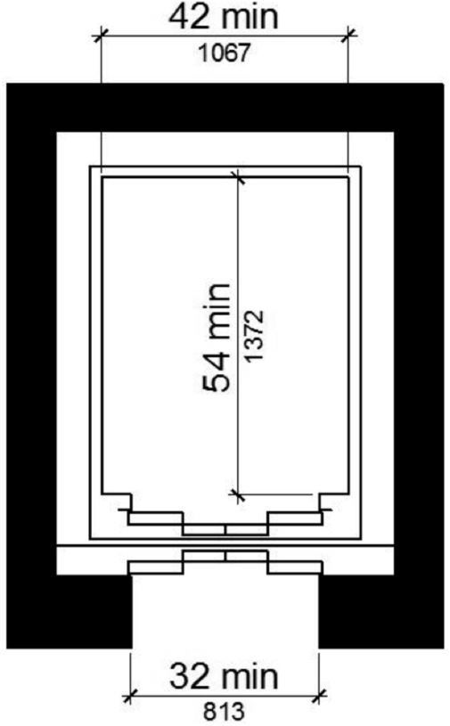
(a) new construction
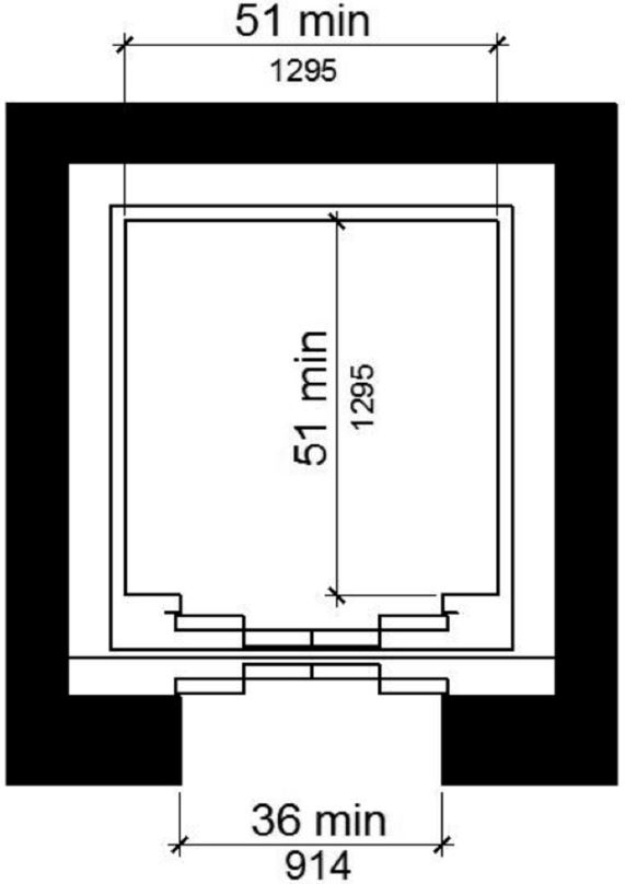
(b) Exception 1
(c) reserved
FIGURE 11B-408.4.1 LIMITED-USE/LIMITED-APPLICATION (LULA) ELEVATOR CAR DIMENSIONS ‡‡
11B-408.4.2 Floor surfaces.
Floor surfaces in elevator cars shall comply with Sections 11B-302 and 11B-303.
11B-408.4.3 Platform to hoistway clearance.
The platform to hoistway clearance shall comply with Section 11B-407.4.3.
11B-408.4.4 Leveling.
Elevator car leveling shall comply with Section 11B-407.4.4.
11B-408.4.5 Illumination.
Elevator car illumination shall comply with Section 11B-407.4.5.
11B-408.4.6 Car controls.
Elevator car controls shall comply with Section 11B-407.4.6. Control panels shall be centered on a side wall.
11B-408.4.7 Designations and indicators of car controls.
Designations and indicators of car controls shall comply with Section 11B-407.4.7.
11B-408.4.8 Emergency communications.
Car emergency signaling devices complying with Section 11B-407.4.9 shall be provided.
11B-409.1 General.
Private residence elevators that are provided within a residential dwelling unit required to provide mobility features complying with Sections 11B-809.2 through 11B-809.4 shall comply with Section 11B-409 and with ASME A17.1. They shall be passenger elevators as classified by ASME A17.1. Elevator operation shall be automatic.

DSA regulates the usability of elevators and platform (wheelchair) lifts for persons with disabilities. Accessibility scoping requirements for elevators and lifts are located in Sections 11B-206.6 and 11B-207.6 [sic]; technical requirements are located in Sections 11B-407, 11B-408, 11B-409 and 11B-410. ◼
11B-409.2 Call buttons.
Call buttons shall be ¾ inch (19.1 mm) minimum in the smallest dimension and shall comply with Section 11B-309.
11B-409.3 Elevator doors.
Hoistway doors, car doors, and car gates shall comply with Sections 11B-409.3 and 11B-404.
Exception: Doors shall not be required to comply with the maneuvering clearance requirements in Section 11B-404.2.4.1 for approaches to the push side of swinging doors.
11B-409.3.1 Power operation.
Elevator car and hoistway doors and gates shall be power operated and shall comply with ANSI/BHMA A156.19. Power operated doors and gates shall remain open for 20 seconds minimum when activated.
Exception: In elevator cars with more than one opening, hoistway doors and gates shall be permitted to be of the manual-open, self-close type.
11B-409.3.2 Location.
Elevator car doors or gates shall be positioned at the narrow end of the clear floor spaces required by Section 11B-409.4.1.
11B-409.4 Elevator cars.
Private residence elevator cars shall comply with Section 11B-409.4.
11B-409.4.1 Inside dimensions of elevator cars.
Elevator cars shall provide a clear floor space of 36 inches (914 mm) minimum by 48 inches (1219 mm) minimum and shall comply with Section 11B-305.
11B-409.4.2 Floor surfaces.
Floor surfaces in elevator cars shall comply with Sections 11B-302 and 11B-303.
11B-409.4.3 Platform to hoistway clearance.
The clearance between the car platform and the edge of any landing sill shall be 1½ inch (38 mm) maximum.
11B-409.4.4 Leveling.
Each car shall automatically stop at a floor landing within a tolerance of ½ inch (12.7 mm) under rated loading to zero loading conditions.
11B-409.4.5 Illumination levels.
Elevator car illumination shall comply with Section 11B-407.4.5.
11B-409.4.6 Car controls.
Elevator car control buttons shall comply with Sections 11B-409.4.6, 11B-309.3, 11B-309.4, and shall be raised or flush.
11B-409.4.6.1 Size.
Control buttons shall be ¾ inch (19.1 mm) minimum in their smallest dimension.
11B-409.4.6.2 Location.
Control panels shall be on a side wall, 12 inches (305 mm) minimum from any adjacent wall.
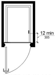
FIGURE 11B-409.4.6.2 LOCATION OF PRIVATE RESIDENCE ELEVATOR CONTROL PANEL
11B-409.4.7 Emergency communications.
Emergency two-way communication systems shall comply with Section 11B-409.4.7.
11B-409.4.7.1 Type.
A telephone and emergency signal device shall be provided in the car.
11B-409.4.7.2 Operable parts.
The telephone and emergency signaling device shall comply with Sections 11B-309.3 and 11B-309.4.
11B-409.4.7.3 Compartment.
If the telephone or device is in a closed compartment, the compartment door hardware shall comply with Section 11B-309.
11B-409.4.7.4 Cord.
The telephone cord shall be 29 inches (737 mm) long minimum.
11B-410.1 General.
Platform lifts shall comply with ASME A18.1. Platform lifts shall not be attendant-operated and shall provide unassisted entry and exit from the lift.

The ADA and other Federal civil rights laws require that accessible features be maintained in working order so that they are accessible to and usable by those people they are intended to benefit. Building owners are reminded that the ASME A18 Safety Standard for Platform Lifts and Stairway Chairlifts requires routine maintenance and inspections. Isolated or temporary interruptions in service due to maintenance or repairs may be unavoidable; however, failure to take prompt action to effect repairs could constitute a violation of Federal laws and these requirements. ◼

DSA regulates the usability of elevators and platform (wheelchair) lifts for persons with disabilities. Accessibility scoping requirements for elevators and lifts are located in Sections 11B-206.6 and 11B-206.7; technical requirements are located in Sections 11B-407, 11B-408, 11B-409 and 11B-410. ◼
11B-410.2 Floor surfaces.
Floor surfaces in platform lifts shall comply with Sections 11B-302 and 11B-303.
11B-410.4 Platform to runway clearance.
The clearance between the platform sill and the edge of any runway landing shall be 1¼ inch (32 mm) maximum.
11B-410.5 Operable parts.
Controls for platform lifts shall comply with Section 11B-309.
11B-410.6 Doors and gates.
Platform lifts shall have low-energy power-operated doors or gates complying with Section 11B-404.3. Doors shall remain open for 20 seconds minimum. End doors and gates shall provide a clear width 32 inches (813 mm) minimum. Side doors and gates shall provide a clear width 42 inches (1067 mm) minimum.
Exception: Platform lifts serving two landings maximum and having doors or gates on opposite sides shall be permitted to have self-closing manual doors or gates.
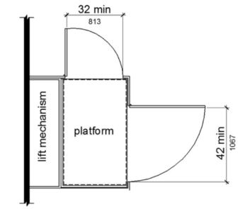
FIGURE 11B-410.6 PLATFORM LIFT DOORS AND GATES
11B-410.7 Landing size.
The minimum size of landings at platform lifts shall be 60 inches by 60 inches (1524 mm by 1524 mm).
ETA Editor's Note
There are no requirements for landing size in 2010 ADA Standards, although the door maneuvering clearance requirements at 404.2.4 should be applicable outside the platform.
11B-410.8 Restriction sign.
A sign complying with Section 11B-703.5 shall be posted in a conspicuous place at each landing and within the platform, enclosure stating “No Freight” and include the International Symbol of Accessibility complying with Section 11B-703.7.2.1.

CCR, Title 8, Section 3094 provides safety regulations for Vertical Platform (Wheelchair) Lifts. This section includes requirements which address platform size and gate configurations for lifts with 90-degree egress, and additionally requires signs posted at the landings as follows:
- International Symbol of Accessibility,
- lift capacity,
- the telephone number to call in case of emergency, and
- the lift shall not be used to transport materials or equipment. ◼
In addition to the accessibility requirements of the building code, Vertical Platform (Wheelchair) Lifts are required to comply with the applicable provisions of the Elevator Code, CCR, Title 8, Section 3142.1, which provides safety regulations for lifts. This section incorporates ASME A18.1-2003, sections 2 and 5 by reference, and requires compliance with CCR, Title 8, Sections 3094.2(d), 3094.2(e), 2094.2(g), and 3094.2(p).
These regulations address technical requirements for lifts, including platform size, gate configurations for lifts with 90-degree egress, and required signage as follows:
- lift capacity, and
- “No Freight” prohibiting the transport of materials or equipment. ◼
11B-411.1 General.
Destination-oriented elevators shall comply with Section 11B-411 and with ASME A17.1. They shall be passenger elevators as classified by ASME A17.1. Elevator operation shall be automatic.
11B-411.1.1 Floor designations.
In facilities served by destination-oriented elevator systems, floor designations shall be numeric characters only. Floor designations shall be "one" (1) or "zero" (0) at the main entry level and shall increase by one for each successive higher story or level. The initial floor below the main entry level shall be designated “minus one” (-1) and the designation for each successive lower story or level shall decrease by one. Stories or levels shall not be designated by alphabetic characters.
Exceptions:
- In existing facilities where new elevators are installed or existing elevators are altered into a destination-oriented elevator system, levels within stories, such as mezzanines located above or below the main entry level shall be permitted to be designated with an alpha-numeric character such as "M2", indicating "mezzanine" and the "story number", respectively, in which it is located, provided there is no duplication with alphanumeric designations of elevator cars in the facility.
- Non-successive floor numbering shall be permitted where a specific floor number is omitted or where a floor is frequented only by service personnel for maintenance, repair or occasional monitoring of equipment.
11B-411.1.2 Car designations.
Elevator cars shall be designated with a single alphabetic character. For elevators programmed to the same hall call console or group of hall call consoles, each elevator car shall be designated with a different single alphabetic character.
Exception: Elevator systems with more than 26 elevators shall be permitted to use alpha-numeric designations such as “A1”.
11B-411.2.1 Hall call consoles.
Hall call consoles shall comply with Sections 11B-411.2.1 and 11B-309.
11B-411.2.1.1 Location.
Hall call consoles shall be wall-mounted. On floors with a building entry, including parking and transfer levels, each hoistway entrance shall be adjacent to a hall call console. On other floors, a minimum of one hoistway entrance shall be adjacent to a hall call console.
Exception: Hall call consoles beyond those required by Section 11B-411.2.1.1 shall be permitted to be provided outside the elevator landing and to be wall-mounted, pedestal-mounted, or mounted on a kiosk or security turnstile.
11B-411.2.1.2 Required features.
Hall call consoles shall include a touch screen or keypad with display screen, an accessibility function button, and audio output loudspeaker.
Keypads shall be in a 12-key ascending telephone keypad layout. Characters and symbols shall be centered on the corresponding button. The number five key shall have a single raised dot. The dot shall have a base diameter of 0.118 inch (3 mm) minimum and 0.120 inch (3.05 mm) maximum and a height of 0.025 inch (0.6 mm) minimum and 0.037 inch (0.9 mm) maximum. Keypads shall have a star («) on the lower left button and a minus sign (-) on the lower right button. From any level above and below the main egress level, when the star button is pressed an elevator shall be dispatched to the main egress level.
Touch screen display shall comply with Section 11B-411.2.1.2.4.
11B-411.2.1.2.3 Accessibility function button.
The accessibility function button shall be identified by the International Symbol of Accessibility and a raised indication. The International Symbol of Accessibility shall comply with Section 11B-703.7.2.1, and shall be 5/8 inch (15.9 mm) minimum in height. The indication shall be three raised dots. Each dot shall have a base diameter of 0.059 inch (1.5 mm) minimum and 0.063 inch (1.6 mm) maximum and a height of 0.025 inch (0.6 mm) minimum and 0.037 inch (0.9 mm) maximum. The dots shall be spaced ¼ inch (6.4 mm), measured center to center, in the form of an equilateral triangle with a vertex pointing up. The accessibility function button shall not be provided with a key repeat function.
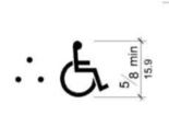
Visual and Raised Information
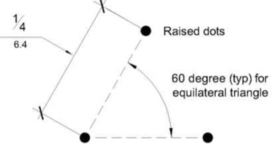
Visual and Raised Information
FIGURE 11B-411.2.1.2.3 DESTINATION-ORIENTED ELEVATOR ACCESSIBILITY FUNCTION BUTTON INDICATION
11B-411.2.1.2.4 Display screen.
Upon activation of the accessibility function button, the display screen shall display information including but not limited to, operating instructions, user input confirmation, elevator assignment characters, direction to the assigned elevator, and error messages. The display screen shall comply with Section 11B-411.2.1.2.4.
Display screens shall provide contrast with light characters and symbols on a dark background or dark characters and symbols on a light background. The background shall be solid and static.
Elevator assignment characters shall be 1 inch high (25 mm) minimum.
Elevator assignment characters shall be displayed for a minimum of 5 seconds.
Upon activation of the accessibility function button, the audio output shall provide verbal announcements, including but not limited to, operating instructions, user input confirmation, announcement of the elevator assignment characters, direction to the assigned elevator, and error messages. Audio output shall be recorded or digitized human speech, and shall be delivered through a loudspeaker. Auditory volume shall be at least 10 dB above ambient sound level, but shall not exceed 80 dB, measured 36 inches (914 mm) in front of the console. At hall call console locations where the ambient sound level varies, auditory volume shall be maintained at the required volume by an automatic gain control or shall be set at not less than 75 dB.
11B-411.2.1.3 Arrangement.
Hall call console arrangement of required features shall comply with Section 11B-411.2.1.3.
11B-411.2.1.3.1 Keypad call console arrangement.
Where keypad call consoles are provided, the display screen shall be located directly above the keypad. The accessibility function button shall be located directly below the keypad at a height of 36 inches (914 mm) to 42 inches (1067 mm) above the finish floor.
11B-411.2.1.3.2 Touch screen call console arrangement.
Where touch screen call consoles are provided, the touch screen shall be located directly above the accessibility function button. The accessibility function button shall be located at a height of 36 inches (914 mm) to 42 inches (1067 mm) above the finish floor.
11B-411.2.1.3.3 Proximity of required elements.
Required features shall be provided on a hall call console assembly or as individual elements grouped in close proximity.
Display screens and touch screens shall be positioned so glare is reduced on the screen. Keypads or buttons shall slope away from the user at 15 to 25 degrees from the vertical plane. Touch screens shall be sloped away from the user at 7 to 25 degrees from the vertical plane.
11B-411.2.1.4 Additional features.
Hall call console additional features, if provided, shall comply with Sections 11B-309 and 11B-411.2.1.4.
11B-411.2.1.4.1 Hall call console additional buttons.
Hall call console buttons provided in addition to the accessibility function button and keypad buttons shall comply with Section 11B-411.2.1.4.1. Buttons in addition to the accessibility function button are not permitted on hall call consoles using a touch screen.
11B-411.2.1.4.1.1 Arrangement.
Buttons shall be arranged in columns to the right of the keypad with a minimum horizontal spacing of 1.5 times the horizontal spacing between the numeric keys and with the same vertical spacing as the numeric keys.
11B-411.2.1.4.1.2 Identification.
Buttons shall be identified by raised characters and symbols, white on a black background, complying with Section 11B-703.2 and Braille complying with Section 11B-703.3. Identification shall be placed immediately to the left of the control button to which the designation applies.
11B-411.2.1.4.2 Security or access controls.
Security or access control system card readers associated with elevator operation shall be in close proximity to each hall call console in a consistent manner throughout the facility.
11B-411.2.1.5 Button requirements.
Keypad buttons, the accessibility function button, and additional hall call console buttons shall comply with Section 11B-411.2.1.5.
Buttons shall have square shoulders, be 3/4 inch (19.1 mm) minimum in the smallest dimension and shall be raised 1/8 inch (3.2 mm) plus or minus 1/32 inch (0.8 mm) above the surrounding surface. The buttons shall be activated by a mechanical motion that is detectable.
Characters and symbols on buttons, where provided, shall be white on a black background.
11B-411.2.1.6 Identification of floors served.
In buildings with two or more elevator banks, each serving a different group of specific floors, hall call consoles located on floors with a building entry, including parking and transfer levels, shall be provided with signs complying with Sections 11B-703.2, 11B-703.3, and 11B-703.5 on the surface of or above the hall call console stating “FLOORS n1 – n2”, where n1 - n2 represents the range of floors served. Characters shall be white on a black background. When the accessibility function button is pressed, the audio output shall provide a verbal announcement of the floors served by the elevator group.
11B-411.2.1.7 Elevator car assignment.
When the accessibility function button is pressed, elevator car assignment shall comply with Section 11B-411.2.1.7.
11B-411.2.1.7.1 Assignment by keypad hall call console.
The audio output shall provide verbal instruction for the user to enter a destination floor. The selected destination floor shall be confirmed by verbal announcement and on the display screen. Verbal and visible indication of an invalid input shall be provided. The display screen shall indicate the elevator assignment characters and a verbal announcement shall be made of the assigned elevator responding to the call. Visual and verbal direction to the assigned elevator shall be provided.
11B-411.2.1.7.2 Assignment by touch screen hall call console.
The audio output shall provide verbal instruction for the user to press the accessibility function button as a response to verbal direction in order to select the destination floor. The selected destination floor shall be confirmed by verbal announcement and on the display screen. Verbal and visible indication of an invalid input shall be provided. The display screen shall indicate the elevator assignment characters and a verbal announcement shall be made of the assigned elevator responding to the call. Visual and verbal direction to the assigned elevator shall be provided.
Exception: In addition to assignment by Section 11B-411.2.1.7.2, a verbal announcement providing the user with an option to select an alternative mode of operation shall be permitted. Alternative operation shall be by one of the following options:
-
Virtual keypad. The size of the keypad shall be a nominal 4 inches (102 mm) wide by 5 inches (127 mm) high in a 12-key ascending telephone keypad layout centered in the console. Characters and symbols shall be centered on the corresponding button. Keypads shall have a star («) on the lower left button and a minus sign (-) on the lower right button. Operation shall be by contact with the touch screen with a press on the key. The audio output shall provide user input confirmation after each key is pressed. Keys shall not be provided with a key repeat function. From any level above and below the main egress level, when the star button is pressed an elevator shall be dispatched to the main egress level.
-
Gesture-based mode of operation. Operation shall be by contact with the touch screen, without specific contact with an icon, and using established non-proprietary gestures for selection and input, including but not limited to tapping, sliding, and tap-hold contact-release to select. The audio output shall provide verbal direction on use of the touch screen, and indication of floor selection options until assignment to the elevator is given.
11B-411.2.1.7.3 Assignment by security credential.
If a security system or other form of access control system is provided, the audio output shall provide a verbal announcement and direction to the location of the access control activation sensor, such as “present security credential at the sensor immediately to the left”. Upon presentation of security credential, the destination floor shall be confirmed by verbal announcement and on the display screen. The display screen shall indicate the elevator assignment characters and a verbal announcement shall be made of the assigned elevator responding to the call. Visual and verbal direction to the assigned elevator shall be provided.
11B-411.2.1.7.4 Adjacency assignment.
The system shall assign an elevator car immediately to the left or right of the hall call console.
Exception: The most adjacent elevator serving the selected floor shall be assigned by hall call consoles located outside the elevator landing.
11B-411.2.2 Elevator car identification at elevator landings.
Elevator car identification shall comply with Section 11B-411.2.2.
11B-411.2.2.1 Visible identification.
Above or adjacent to each elevator car entrance there shall be a visible identification fixture with a car designation character. The identification fixture shall be 80 inches (2032 mm) minimum above the finish floor or ground to the bottom of the fixture. The characters on the fixture shall be upper case with a height of 4 inches (102 mm) minimum complying with Sections 11B-703.5.1, 11B-703.5.3, 11B-703.5.4, 11B-703.5.7 and 11B-703.5.8.
Exception: Existing buildings shall be permitted to have a visible identification fixture with a car designation character adjacent to each elevator car entrance centered at 72 inches (1829 mm) above the finish floor or ground. The character on the fixture shall be upper case with a height of 2 1/2 inches (64 mm) minimum complying with Sections 11B-703.5.1, 11B-703.5.3, 11B-703.5.4, 11B-703.5.7 and 11B-703.5.8.
11B-411.2.2.2 Verbal identification.
When the accessibility function button is pressed, verbal announcement of the car designation shall be provided at the elevator car entrance upon arrival. Audio output shall be recorded or digitized human speech, and shall be delivered through a loudspeaker. The verbal annunciator shall have a frequency of 300 Hz minimum and 3000 Hz maximum. Auditory volume shall be at least 10 dB above ambient sound level, but shall not exceed 80 dB, measured 36 inches (914 mm) in front of the elevator entrance and at 48 inches (1219 mm) above the floor. At elevator entrances where the ambient sound level varies, auditory volume shall be maintained at the required volume by an automatic gain control or shall be set at not less than 75 dB.
11B-411.2.3 Signs on jambs of elevator hoistway entrances.
Signs on jambs of elevator hoistway entrances shall comply with Section 11B-411.2.3.
11B-411.2.3.1 Floor designation signs.
Floor designation signs complying with Sections 11B-703.2 and 11B-703.4.1 shall be provided on both jambs of elevator hoistway entrances. Signs shall be provided in both raised characters and Braille. Raised characters shall be 2 inches (51 mm) high. A raised star placed to the left of the floor designation, shall be provided on both jambs at the main entry level. The outside diameter of the star shall be 2 inches (51 mm) and all points shall be of equal length. Raised characters, including the star, shall be white on a black background. Braille complying with Section 11B-703.3 shall be placed below the corresponding raised characters and the star. The Braille translation for the star shall be “MAIN”. Applied plates are acceptable if they are permanently fixed to the jamb.
11B-411.2.3.2 Car designation signs.
Car designation signs complying with Sections 11B-703.2 and 11B-703.4.1 shall be provided on both jambs of the hoistway immediately below the floor designation. Signs shall be provided in both raised characters and Braille. Raised characters shall be 2 inches (51 mm) high. Raised characters shall be white on a black background. Braille complying with Section 11B-703.3 shall be placed below the corresponding raised characters. Applied plates are acceptable if they are permanently fixed to the jamb.
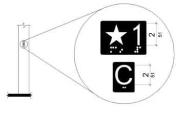
FIGURE 11B-411.2.3 FLOOR DESIGNATION AND CAR DESIGNATION SIGNS ON JAMBS OF DESTINATION-ORIENTED ELEVATOR HOISTWAY ENTRANCES
11B-411.3 Elevator door requirements.
Hoistway and car doors shall comply with Section 11B-411.3.
11B-411.3.1 Type.
Elevator door type shall comply with Section 11B-407.3.1.
11B-411.3.2 Operation.
Elevator hoistway and car doors shall open and close automatically.
11B-411.3.3 Reopening device.
Elevator doors shall be provided with a reopening device complying with Section 11B-411.3.3 that shall stop and reopen a car door and hoistway door automatically if the door becomes obstructed by an object or person.
11B-411.3.3.1 Height.
The height of the reopening device shall comply with Section 11B-407.3.3.1.
11B-411.3.3.2 Contact.
The device contact shall comply with Section 11B-407.3.3.2.
11B-411.3.3.3 Duration.
The door reopening device duration shall comply with Section 11B-407.3.3.3.
11B-411.3.4 Door delay.
Door delay shall comply with Section 11B-407.3.5.
11B-411.3.5 Width.
The width of elevator doors shall comply with Table 11B-407.4.1.
11B-411.4.1 Car dimensions.
Inside dimensions of elevator cars and clear width of elevator doors shall comply with Section 11B-407.4.1.
11B-411.4.2 Floor surfaces.
Floor surfaces in elevator cars shall comply with Section 11B-407.4.2.
11B-411.4.3 Platform to hoistway clearance.
Platform to hoistway clearance shall comply with Section 11B-407.4.3.
11B-411.4.4 Leveling.
Elevator car leveling shall comply with Section 11B-407.4.4.
11B-411.4.5 Illumination.
The level of illumination at the car controls shall comply with Section 11B-407.4.5.
11B-411.4.6 Elevator car controls.
Where provided, elevator car controls shall comply with Sections 11B-411.4.6 and 11B-309.4.
11B-411.4.6.1 Location.
Controls shall be located within one of the reach ranges specified in Section 11B-308.
11B-411.4.6.2 Buttons.
Car control buttons shall comply with Sections 11B-407.4.6.2.1 and 11B-407.4.6.2.4. The car shall not have non-functional, exposed floor buttons.
11B-411.4.6.3 Emergency controls.
Emergency controls shall comply with Section 11B-407.4.6.4.
11B-411.4.7 Designations and indicators of car control buttons.
Designations and indicators of car control buttons shall comply with Section 11B-411.4.7.
11B-411.4.7.1 Type.
Control button type shall comply with Section 11B-407.4.7.1.1.
11B-411.4.7.2 Location.
Raised characters or symbols and Braille designations shall comply with Section 11B-407.4.7.1.2.
11B-411.4.7.3 Symbols.
The control button for the emergency stop, alarm, door open, door close, and phone, shall be identified with raised symbols and Braille as shown in Table 11B-407.4.7.1.3.
11B-411.4.7.4 Button spacing.
Button spacing shall comply with Section 11B-407.4.7.1.5.
11B-411.4.8 Car position indicators.
Audible and visible car position indicators shall be provided in elevator cars.
11B-411.4.8.1 Visible indicators.
Visible indicators shall comply with Section 11B-411.4.8.1.
Location of indicators shall comply with Section 11B-407.4.8.1.2.
11B-411.4.8.2 Audible indicators.
Audible indicators shall comply with Section 11B-411.4.8.2.
The signal shall be an automatic verbal annunciator which announces the floor at which the car is about to stop.
The verbal annunciator signal level shall comply with Section 11B-407.4.8.2.2.
The verbal annunciator frequency shall comply with Section 11B-407.4.8.2.3.
11B-411.4.9 Emergency communication.
Emergency communication shall comply with Section 11B-407.4.9.
11B-411.4.10 Support rail.
Support rails complying with Section 11B-407.4.10 shall be provided on at least one wall of the car.
11B-411.4.11 Floor destination indicators.
There shall be on each elevator car door jamb a visual display indicating floor destinations.
11B-411.4.11.1 Height.
Floor destination characters shall be 1 inch (25 mm) high minimum complying with Section 11B-703.5.3.
11B-411.4.11.2 Contrast.
Visual display shall provide contrast with light characters on a dark background or dark characters on a light background. The background shall be solid and static.
11B-411.4.11.3 Duration.
Floor destination characters shall be displayed upon elevator car arrival at the input floor and shall not extinguish until the elevator car arrives at the destination floor.
User Comments/Questions
Add Comment/Question