2019 California Standards for Accessible Design Guide (effective January 1, 2020 with July 1, 2021 amendments)
DIVISION 6: PLUMBING ELEMENTS AND FACILITIES
11B-601.1 Scope.
The provisions of Division 6 shall apply where required by Division 2 or where referenced by a requirement in this chapter.
11B-602 Drinking fountains and bottle filling stations
11B-602.1 General.
Drinking fountains shall comply with Sections 11B-307 and 11B-602.
11B-602.2 Clear floor space.
Units shall have a clear floor or ground space complying with Section 11B-305 positioned for a forward approach and centered on the unit. Knee and toe clearance complying with Section 11B-306 shall be provided.
Exception: A parallel approach complying with Section 11B-305 shall be permitted at units for children's use where the spout is 30 inches (762 mm) maximum above the finish floor or ground and is 3½ inches (89 mm) maximum from the front edge of the unit, including bumpers.
11B-602.3 Operable parts.
Operable parts shall comply with Section 11B-309. The flow of water shall be activated by a manually operated system that is front mounted or side mounted and located within 6 inches (152 mm) of the front edge of the fountain or an automatic electronically controlled device.
[2010 ADA Standards] 602.3 Operable Parts. Operable parts shall comply with 309.
11B-602.4 Spout height.
Spout outlets shall be 36 inches (914 mm) maximum above the finish floor or ground.
11B-602.5 Spout location.
The spout shall be located 15 inches (381 mm) minimum from the vertical support and 5 inches (127 mm) maximum from the front edge of the unit, including bumpers.
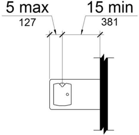
FIGURE 11B-602.5 DRINKING FOUNTAIN SPOUT LOCATION
11B-602.6 Water flow.
The spout shall provide a flow of water 4 inches (102 mm) high minimum and shall be located 5 inches (127 mm) maximum from the front of the unit. The angle of the water stream shall be measured horizontally relative to the front face of the unit. Where spouts are located less than 3 inches (76 mm) of the front of the unit, the angle of the water stream shall be 30 degrees maximum. Where spouts are located between 3 inches (76 mm) and 5 inches (127 mm) maximum from the front of the unit, the angle of the water stream shall be 15 degrees maximum.

11B-602.7 Drinking fountains for standing persons.
Spout outlets of drinking fountains for standing persons shall be 38 inches (965 mm) minimum and 43 inches (1092 mm) maximum above the finish floor or ground.
11B-602.8 Depth.
Wall- and post-mounted cantilevered drinking fountains shall be 18 inches (457 mm) minimum and 19 inches (483 mm) maximum in depth.
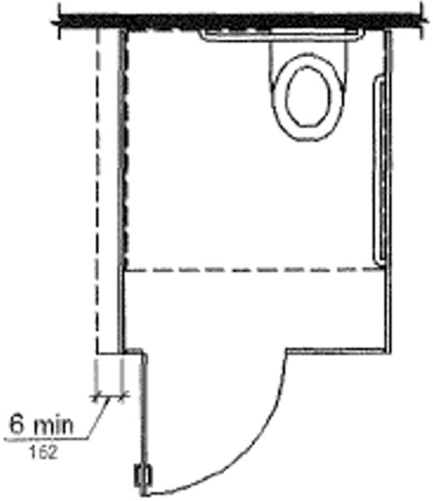
11B-602.9 Pedestrian protection.
All drinking fountains shall either be located completely within alcoves, positioned completely between wing walls, or otherwise positioned so as not to encroach into pedestrian ways. The protected area within which a drinking fountain is located shall be 32 inches (813 mm) wide minimum and 18 inches (457 mm) deep minimum, and shall comply with Section 11B-305.7. When used, wing walls or barriers shall project horizontally at least as far as the drinking fountain and to within 6 inches (152 mm) vertically from the floor or ground surface.
11B-602.10 Bottle filling stations.
Bottle filling stations shall comply with Sections 11B-307 and 11B-309.
Exception: Where bottle filling stations are provided at a drinking fountain for standing persons, the bottle filling station is not required to comply with this section provided a bottle filling station is located at the drinking fountain complying with Sections 11B-602.2 through 11B-602.6.
11B-603.1 General.
Toilet and bathing rooms shall comply with Section 11B-603.
11B-603.2 Clearances.
Clearances shall comply with Section 11B-603.2.
11B-603.2.1 Turning space.
Turning space complying with Section 11B-304 shall be provided within the room.
11B-603.2.2 Overlap.
Required clear floor spaces, clearance at fixtures, and turning space shall be permitted to overlap.
11B-603.2.3 Door swing.
Doors shall not swing into the clear floor space or clearance required for any fixture. Doors to accessible water closet compartments shall be permitted to encroach into the turning space without limitation. Other than doors to accessible water closet compartments, a door in any position, shall be permitted to encroach into the turning space by 12 inches (305 mm) maximum.
[2010 ADA Standards] 603.2.3 Door Swing. Doors shall not swing into the clear floor space or clearance required for any fixture. Doors shall be permitted to swing into the required turning space.
Exceptions:
-
Reserved.
[2010 ADA Standards] 1. Doors to a toilet room or bathing room for a single occupant accessed only through a private office and not for common use or public use shall be permitted to swing into the clear floor space or clearance provided the swing of the door can be reversed to comply with 603.2.3.
-
Where the toilet room or bathing room is for individual use and a clear floor space complying with Section 11B-305.3 is provided within the room beyond the arc of the door swing, doors shall be permitted to swing into the clear floor space or clearance required for any fixture.
-
In residential dwelling units complying with Section 11B-233.3.1.1, doors shall be permitted to swing over the turning space without limitation.

Limiting the encroachment of door swings into the wheelchair turning space, and lacking Exception 1 above allowed by 2010 ADA Standards, the CBC requirements pertaining to toilet or bathing room clearances are more stringent.
11B-603.3 Mirrors.
Mirrors located above lavatories or countertops shall be installed with the bottom edge of the reflecting surface 40 inches (1016 mm) maximum above the finish floor or ground. Mirrors not located above lavatories or countertops shall be installed with the bottom edge of the reflecting surface 35 inches (889 mm) maximum above the finish floor or ground.

11B-603.4 Coat hooks, shelves and medicine cabinets.
Coat hooks shall be located within one of the reach ranges specified in Section 11B-308. Shelves shall be located 40 inches (1016 mm) minimum and 48 inches (1219 mm) maximum above the finish floor. Medicine cabinets shall be located with a usable shelf no higher than 44 inches (1118 mm) maximum above the finish floor.
[2010 ADA Standards] 603.4 Coat Hooks and Shelves. Coat hooks shall be located within one of the reach ranges specified in 308. Shelves shall be located 40 inches (1015 mm) minimum and 48 inches (1220 mm) maximum above the finish floor.
11B-603.5 Accessories.
Where towel or sanitary napkin dispensers, waste receptacles, or other accessories are provided in toilet facilities, at least one of each type shall be located on an accessible route. All operable parts, including coin slots, shall be 40 inches (1016 mm) maximum above the finish floor.
Exception: Baby diaper changing stations are not required to comply with Section 11B-603.5.
ETA Editor's Note
11B-603.6 Guest room toilet and bathing rooms.
Toilet and bathing rooms within guest rooms that are not required to provide mobility features complying with Section 11B-806.2 shall provide all toilet and bathing fixtures in a location that allows a person using a wheelchair measuring 30 inches by 48 inches (762 mm by 1219 mm) to touch the wheelchair to any lavatory, urinal, water closet, tub, sauna, shower stall and any other similar sanitary installation, if provided.
11B-604.1 General.
Water closets and toilet compartments shall comply with Sections 11B-604.2 through 11B-604.8.
Exception: Water closets and toilet compartments for children's use shall be permitted to comply with Section 11B-604.9.
11B-604.2 Location.
The water closet shall be positioned with a wall or partition to the rear and to one side. The centerline of the water closet shall be 17 inches (432 mm) minimum to 18 inches (457 mm) maximum from the side wall or partition, except that the water closet shall be 17 inches (432 mm) minimum and 19 inches (483 mm) maximum from the side wall or partition in the ambulatory accessible toilet compartment specified in Section 11B-604.8.2. Water closets shall be arranged for a left-hand or right-hand approach.
[2010 ADA Standards] 604.2 Location. The water closet shall be positioned with a wall or partition to the rear and to one side. The centerline of the water closet shall be 16 inches (405 mm) minimum to 18 inches (455 mm) maximum from the side wall or partition, except that the water closet shall be 17 inches (430 mm) minimum and 19 inches (485 mm) maximum from the side wall or partition in the ambulatory accessible toilet compartment specified in 604.8.2. Water closets shall be arranged for a left-hand or right-hand approach.
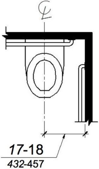
(a) wheelchair accessible water closets
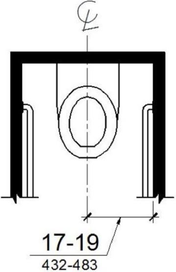
(b) ambulatory accessible water closets
FIGURE 11B-604.2 WATER CLOSET LOCATION ‡‡
11B-604.3 Clearance.
Clearances around water closets and in toilet compartments shall comply with Section 11B-604.3.
11B-604.3.1 Size.
Clearance around a water closet shall be 60 inches (1524 mm) minimum measured perpendicular from the side wall and 56 inches (1422 mm) minimum measured perpendicular from the rear wall. A minimum 60 inches (1524 mm) wide and 48 inches (1219 mm) deep maneuvering space shall be provided in front of the water closet.
Exception: In residential dwelling units complying with Section 11B-233.3.1.1, maneuvering space in front of the water closet shall be a minimum 60 inches (1524 mm) wide and 36 inches (914 mm) deep.
[2010 ADA Standards] 604.3.1 Size. Clearance around a water closet shall be 60 inches (1525 mm) minimum measured perpendicular from the side wall and 56 inches (1420 mm) minimum measured perpendicular from the rear wall.
ETA Editor's Note
The CBC 11B-604.3.1 requirement for maneuvering space in front of accessible water closets exceeds the 2010 ADA Standards requirement for water closet clear floor space, but a door may swing into the added clearance.
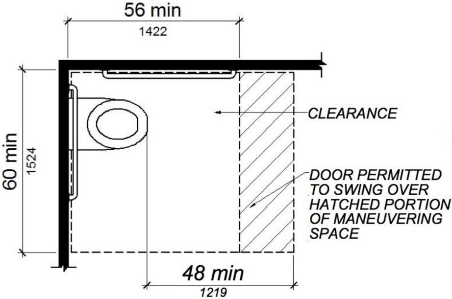
FIGURE 11B-604.3.1 SIZE OF CLEARANCE AT WATER CLOSETS ‡‡
11B-604.3.2 Overlap.
The required clearance around the water closet shall be permitted to overlap the water closet, associated grab bars, dispensers, sanitary napkin disposal units, coat hooks, shelves, accessible routes, clear floor space and clearances required at other fixtures, and the turning space. No other fixtures or obstructions shall be located within the required water closet clearance.
ETA Editor's Note
The Office of Statewide Health Planning and Development (OSHPD), which has jurisdiction over hospitals and long-term care facilities in California, issued Code Application Notice CAN 2-11B, dated 9/9/14, which includes the following interpretation of Subsection 11B-604.3.2:
Showers are fixtures including a 30 inch x 60 inch clear receptor with a minimum/maximum slope of ¼ inch per foot to a drain (refer to CPC Section 408.5 and CBC Section 11B-608.9), and a threshold, between the shower receptor and the fixture clearance provided outside the shower (CBC Section 11B-608.2.2.1) with a maximum height of ½ inch (CBC Section 11B-608.7). The required clearance around a water closet may overlap the clearance required outside the shower but not overlap the shower fixture threshold or receptor.
As of the initial publication of this Guide, OSHPD has not updated CAN 2-11B for applicability to 2019 CBC. Since there is no change to the wording of Subsection 11B-604.3.2 from 2013 CBC to 2019 CBC, there is no reason to expect that OSHPD will change its interpretation.
Exception: In residential dwelling units, a lavatory complying with Section 11B-606 shall be permitted on the rear wall 26 inches (660 mm) minimum from the water closet centerline to allow for the installation of a grab bar where the clearance at the water closet is 66 inches (1676 mm) minimum measured perpendicular from the rear wall.

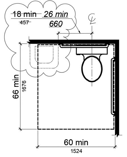
Figure 11B-604.3.2 (Exception)
OVERLAP OF WATER CLOSET CLEARANCE IN RESIDENTIAL DWELLING UNITS
11B-604.4 Seats.
The seat height of a water closet above the finish floor shall be 17 inches (432 mm) minimum and 19 inches (483 mm) maximum measured to the top of the seat. Seats shall not be sprung to return to a lifted position. Seats shall be 2 inches (51 mm) high maximum.
[2010 ADA Standards] 604.4 Seats. The seat height of a water closet above the finish floor shall be 17 inches (430 mm) minimum and 19 inches (485 mm) maximum measured to the top of the seat. Seats shall not be sprung to return to a lifted position.
Exceptions:
1. Reserved.
[2010 ADA Standards] 1. A water closet in a toilet room for a single occupant accessed only through a private office and not for common use or public use shall not be required to comply with 604.4.
2. In residential dwelling units, the height of water closets shall be permitted to be 15 inches (381 mm) minimum and 19 inches (483 mm) maximum above the finish floor measured to the top of the seat.
3. A 3-inch (76 mm) high seat shall be permitted only in alterations where the existing fixture is less than 15 inches (381 mm) high.
11B-604.5 Grab bars.
Grab bars for water closets shall comply with Section 11B-609. Grab bars shall be provided on the side wall closest to the water closet and on the rear wall. Where separate grab bars are required on adjacent walls at a common mounting height, an L-shaped grab bar meeting the dimensional requirements of Sections 11B-604.5.1 and 11B-604.5.2 shall be permitted.
[2010 ADA Standards] 604.5 Grab Bars. Grab bars for water closets shall comply with 609. Grab bars shall be provided on the side wall closest to the water closet and on the rear wall.
Exceptions:
1. Reserved.
[2010 ADA Standards] 1. Grab bars shall not be required to be installed in a toilet room for a single occupant accessed only through a private office and not for common use or public use provided that reinforcement has been installed in walls and located so as to permit the installation of grab bars complying with 604.5.
2. In residential dwelling units, grab bars shall not be required to be installed in toilet or bathrooms provided that reinforcement has been installed in walls and located so as to permit the installation of grab bars complying with Section 11B-604.5.

3. In detention or correction facilities, grab bars shall not be required to be installed in housing or holding cells that are specially designed without protrusions for purposes of suicide prevention.
11B-604.5.1 Side wall.
The side wall grab bar shall be 42 inches (1067 mm) long minimum, located 12 inches (305 mm) maximum from the rear wall and extending 54 inches (1372 mm) minimum from the rear wall with the front end positioned 24 inches (610 mm) minimum in front of the water closet.
[2010 ADA Standards] 604.5.1 Side Wall. The side wall grab bar shall be 42 inches (1065 mm) long minimum, located 12 inches (305 mm) maximum from the rear wall and extending 54 inches (1370 mm) minimum from the rear wall.
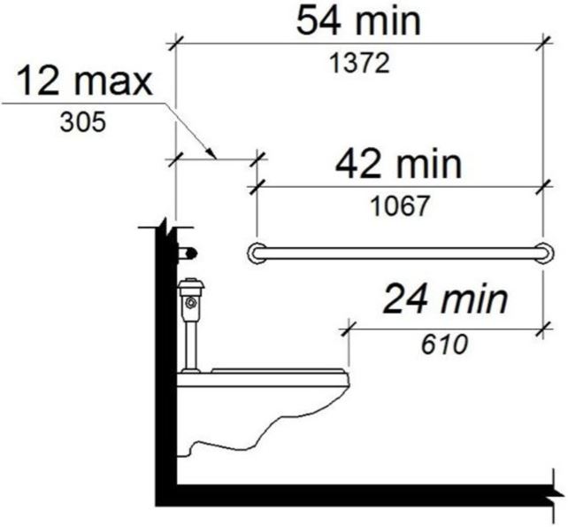
FIGURE 11B-604.5.1 SIDE WALL GRAB BAR AT WATER CLOSETS ‡‡
11B-604.5.2 Rear wall.
The rear wall grab bar shall be 36 inches (914 mm) long minimum and extend from the centerline of the water closet 12 inches (305 mm) minimum on one side and 24 inches (610 mm) minimum on the other side.
Exceptions:
- The rear grab bar shall be permitted to be 24 inches (610 mm) long minimum, centered on the water closet, where wall space does not permit a length of 36 inches (914 mm) minimum due to the location of a recessed fixture adjacent to the water closet.
- Where an administrative authority requires flush controls for flush valves to be located in a position that conflicts with the location of the rear grab bar, then the rear grab bar shall be permitted to be split or shifted to the open side of the toilet area.
ETA Editor's Note
The Office of Statewide Health Planning and Development (OSHPD), which has jurisdiction over hospitals and long-term care facilities in California, issued Code Application Notice CAN 2-11B, dated 9/9/14, which includes the following interpretation of Subsection 11B-604.5.2:
CBC Section 1224.14.2.7 requires the provision of a flushing-rim clinical sink in the soiled utility room of a nursing unit. There is an allowance to eliminate the clinical sink if facilities for cleaning bedpans are provided elsewhere. CPC Table 4-2 Footnote 14 allows the clinical sink to be deleted if all bedrooms in the nursing unit are provided with adjoining toilets with bedpan flushing devices.
Patient toilet rooms with bedpan flushing devices are an allowance, not a requirement. If this approach is pursued, the bedpan flushing device shall not be a unit that results in the need to split or offset the rear grab bar. Section 11B-604.5.2 is not available to accommodate bedpan flushing devices. The gripping surface of the grab bar must be available for the entire 36-inch length without interruption.
Bedpan washing devices that are manufactured as part of a flush valve assembly project above the rear grab bar, obstructing it. OSHPD's interpretation disallows those at the water closets in accessible Patient Toilets. There are wall-mounted bedpan washing devices that could be used instead, taking care not to obstruct either the side or the rear grab bars, or the required clear floor space.
As of the initial publication of this Guide, OSHPD has not updated CAN 2-11B for applicability to 2019 CBC. Since there is no change to the wording of Subsection 11B-604.5.2 Exception 2 from 2013 CBC to 2019 CBC, there is no reason to expect that OSHPD will change its interpretation.
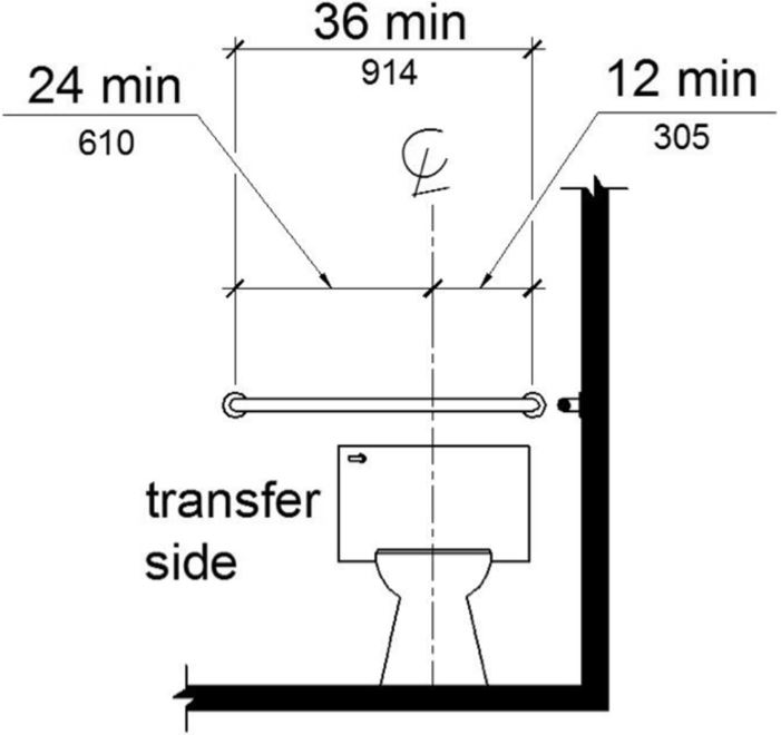
FIGURE 11B-604.5.2 REAR WALL GRAB BAR AT WATER CLOSETS
11B-604.6 Flush controls.
Flush controls shall be hand operated or automatic. Hand operated flush controls shall comply with Section 11B-309 except they shall be located 44 inches (1118 mm) maximum above the floor. Flush controls shall be located on the open side of the water closet except in ambulatory accessible compartments complying with Section 11B-604.8.2.
[2010 ADA Standards] 604.6 Flush Controls. Flush controls shall be hand operated or automatic. Hand operated flush controls shall comply with 309. Flush controls shall be located on the open side of the water closet except in ambulatory accessible compartments complying with 604.8.2.

11B-604.7 Dispensers and disposal units.
Toilet paper dispensers and sanitary napkin disposal units shall comply with Section 11B-604.7. Combination accessory units are not permitted to encroach into the space required by Section 11B-609.3.
[2010 ADA Standards] 604.7 Dispensers. Toilet paper dispensers shall comply with 309.4 and shall be 7 inches (180 mm) minimum and 9 inches (230 mm) maximum in front of the water closet measured to the centerline of the dispenser. The outlet of the dispenser shall be 15 inches (380 mm) minimum and 48 inches (1220 mm) maximum above the finish floor and shall not be located behind grab bars. Dispensers shall not be of a type that controls delivery or that does not allow continuous paper flow.
11B-604.7.1 Dispensers.
Toilet paper dispensers shall comply with Section 11B-309.4 and shall be 7 inches (178 mm) minimum and 9 inches (229 mm) maximum in front of the water closet measured to the centerline of the dispenser. The outlet of the dispenser shall be below the grab bar, 19 inches (483 mm) minimum above the finish floor and shall not be located behind grab bars. Dispensers shall not be of a type that controls delivery or that does not allow continuous paper flow.
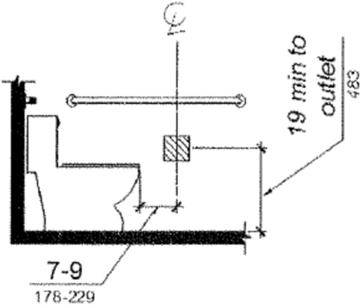
FIGURE 11B-604.7.1 DISPENSER OUTLET LOCATION ‡‡
11B-604.7.2 Disposal units.
Sanitary napkin disposal units, if provided, shall comply with Section 11B-309.4 and shall be wall mounted and located on the sidewall between the rear wall of the toilet and the toilet paper dispenser, adjacent to the toilet paper dispenser. The disposal unit shall be located below the grab bar with the opening of the disposal unit 19 inches minimum (483 mm) above the finish floor.
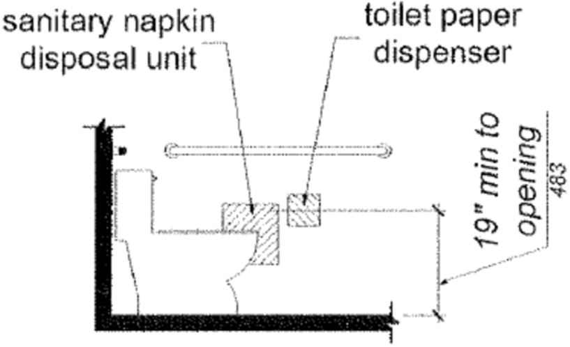
FIGURE 11B-604.7.2 DISPOSAL UNIT LOCATION
11B-604.8 Toilet compartments.
Wheelchair accessible toilet compartments shall meet the requirements of Sections 11B-604.8.1 and 11B-604.8.3. Compartments containing more than one plumbing fixture shall comply with Section 11B-603. Ambulatory accessible compartments shall comply with Sections 11B-604.8.2 and 11B-604.8.3.
11B-604.8.1 Wheelchair accessible compartments.
Wheelchair accessible compartments shall comply with Section 11B-604.8.1.
11B-604.8.1.1 Size.
Wheelchair accessible compartments shall be 60 inches (1524 mm) wide minimum measured perpendicular to the side wall, and 56 inches (1422 mm) deep minimum for wall hung water closets and 59 inches (1499 mm) deep minimum for floor mounted water closets measured perpendicular to the rear wall. Wheelchair accessible compartments shall additionally provide maneuvering space complying with Section 11B-604.8.1.1.1, 11B-604.8.1.1.2, or 11B-604.8.1.1.3, as applicable. Wheelchair accessible compartments for children’s use shall be 60 inches (1524 mm) wide minimum measured perpendicular to the side wall, and 59 inches (1499 mm) deep minimum for wall hung and floor mounted water closets measured perpendicular to the rear wall.


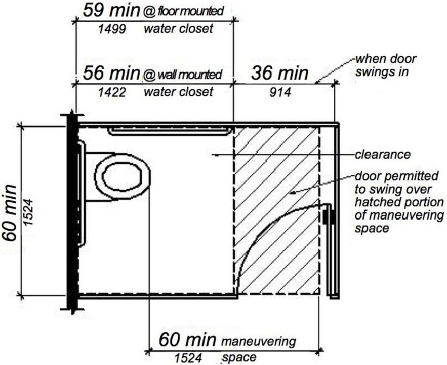
11B-604.8.1.1.1 Maneuvering space with in-swinging door.
In a wheelchair accessible compartment with an in-swinging door, a minimum 60 inches (1524 mm) wide by 36 inches (914 mm) deep maneuvering space shall be provided in front of the clearance required in Section 11B-604.8.1.1. See Figures 11B-604.8.1.1.2(b) and 11B-604.8.1.1.3(b).
11B-604.8.1.1.2 Maneuvering space with side-opening door.
In a wheelchair accessible compartment with a door located in the side wall or partition, either in-swinging or out-swinging, a minimum 60 inches (1524 mm) wide and 60 inches (1524 mm) deep maneuvering space shall be provided in front of the water closet. See Figure 11B-604.8.1.1.2.
(b) in-swinging door
FIGURE 11B-604.8.1.1.2 MANEUVERING SPACE WITH SIDE-OPENING DOOR ‡‡
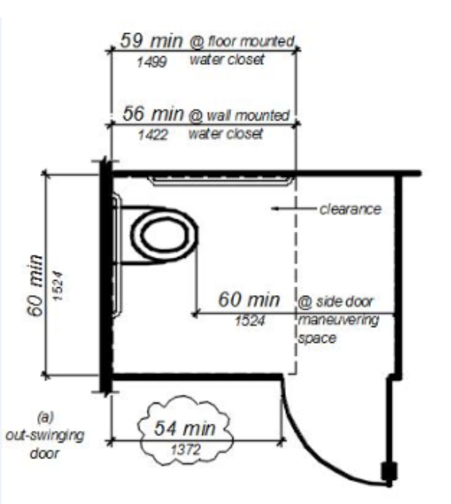
11B-604.8.1.1.3 Maneuvering space with end-opening door.
In a wheelchair accessible compartment with a door located in the front wall or partition (facing the water closet), either in-swinging or out-swinging, a minimum 60 inches (1524 mm) wide and 48 inches (1219 mm) deep maneuvering space shall be provided in front of the water closet. See Figure 11B-604.8.1.1.3.
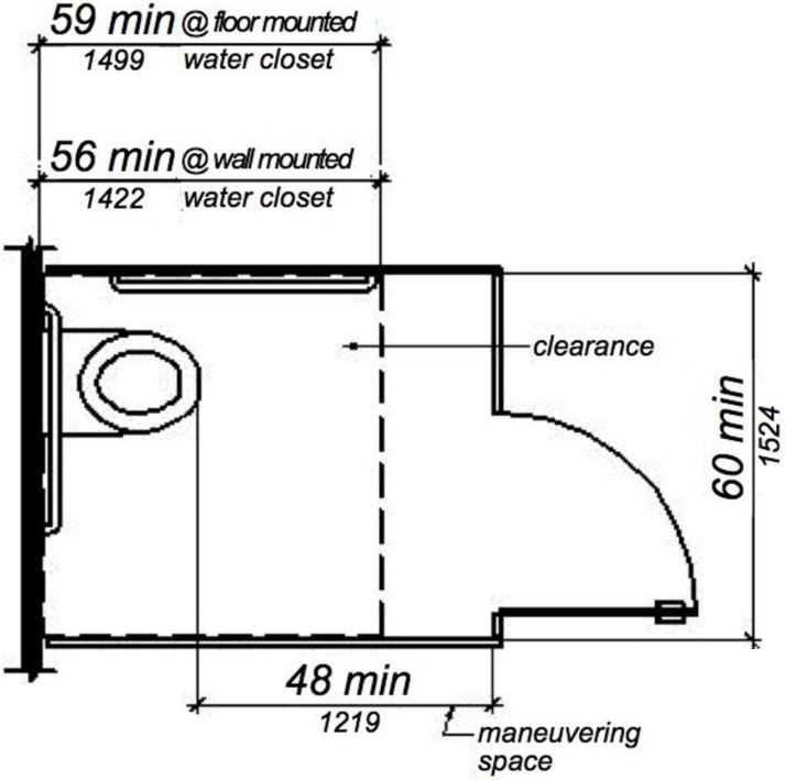
(a) out-swinging door
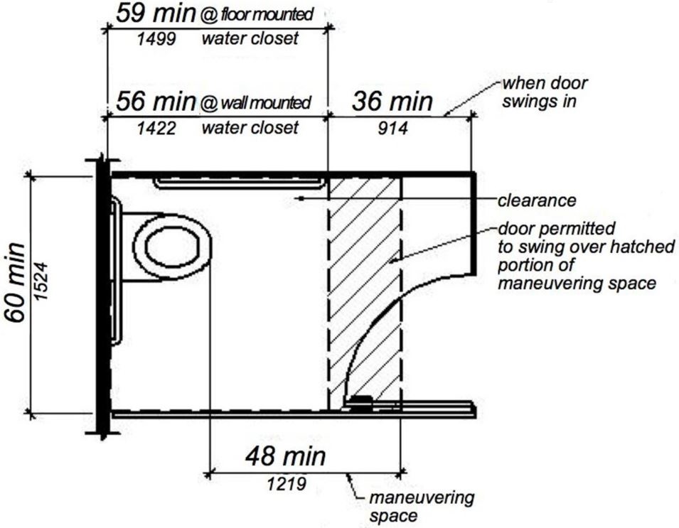
(b) in-swinging door
FIGURE 11B-604.8.1.1.3 MANEUVERING SPACE WITH END-OPENING DOOR ‡‡
11B-604.8.1.2 Doors.
Toilet compartment doors, including door hardware, shall comply with Section 11B-404 except that if the approach is from the push side of the compartment door, clearance between the door side of the compartment and any obstruction shall be 48 inches (1219 mm) minimum measured perpendicular to the compartment door in its closed position. Doors shall be located in the front partition or in the side wall or partition farthest from the water closet. Where located in the front partition, the door opening shall be 4 inches (102 mm) maximum from the side wall or partition farthest from the water closet. Where located in the side wall or partition, the door opening shall be farthest from the water closet and shall be 54 inches (1372 mm) minimum from the rear wall. Where located in the side wall or partition, the door opening shall be 4 inches (102 mm) maximum from the front partition. The door shall be self-closing. A door pull complying with Section 11B-404.2.7 shall be placed on both sides of the door near the latch. Doors shall not swing into the clear floor space or clearance required for any fixture. Doors may swing into that portion of maneuvering space which does not overlap the clearance required at a water closet.
[2010 ADA Standards] 604.8.1.2 Doors. Toilet compartment doors, including door hardware, shall comply with 404 except that if the approach is to the latch side of the compartment door, clearance between the door side of the compartment and any obstruction shall be 42 inches (1065 mm) minimum. Doors shall be located in the front partition or in the side wall or partition farthest from the water closet. Where located in the front partition, the door opening shall be 4 inches (100 mm) maximum from the side wall or partition farthest from the water closet. Where located in the side wall or partition, the door opening shall be 4 inches (100 mm) maximum from the front partition. The door shall be self-closing. A door pull complying with 404.2.7 shall be placed on both sides of the door near the latch. Toilet compartment doors shall not swing into the minimum required compartment area.
Exception: When located at the side of a toilet compartment, the toilet compartment door opening shall provide a clear width of 34 inches (864 mm) minimum.

The door is required to have a latch which is flip-over style, sliding or which otherwise does not require the user to grasp or twist. This is to facilitate latching the door by people with limited hand or finger dexterity.
The last part of this item addresses the required maneuvering space at the compartment door. This space is required to comply with requirements for door maneuvering space in Section 11B-404.2.4, except the space in front of the door shall be no less than 48 inches deep, measured perpendicular to the closed door. Where Figure 11B-404.2.4.1 (f) and (j), specifically allow a 44” minimum maneuvering space perpendicular to doors in general in the closed position, a minimum of 48” must be provided in order to comply with Section 11B-604.8.1.2.
Note that in Figure 11B-404.2.4.1 (c) the front approach requires 12 inches of strike-side clearance on the push side where a door has both a latch and a closer. However, the US Department of Justice has indicated that a self-closing compartment door with a gravity hinge is not considered to be a door with a closer; hence the 12-inch clearance would not be required in this type of design. ◼
ETA Editor's Note
For wheelchair accessible compartments with in-swinging doors, the compartment size required by CBC is nominally the same as required by 2010 ADA Standards. For compartments with out-swinging doors, 2019 CBC requires larger compartments than 2010 ADA Standards due to the 48” minimum maneuvering space required in front of the water closet by 11B-604.8.1.1.3.
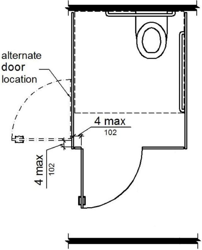
FIGURE 11B-604.8.1.2 WHEELCHAIR ACCESSIBLE TOILET COMPARTMENT DOORS ‡‡
11B-604.8.1.3 Approach.
Compartments shall be arranged for left-hand or right-hand approach to the water closet.
11B-604.8.1.4 Toe clearance.
At least one side partition shall provide a toe clearance of 9 inches (229 mm) minimum above the finish floor and 6 inches (152 mm) deep minimum beyond the compartment-side face of the partition, exclusive of partition support members. Partition components at toe clearances shall be smooth without sharp edges or abrasive surfaces. Compartments for children’s use shall provide a toe clearance of 12 inches (305 mm) minimum above the finish floor.
[2010 ADA Standards] 604.8.1.4 Toe Clearance. The front partition and at least one side partition shall provide a toe clearance of 9 inches (230 mm) minimum above the finish floor and 6 inches (150 mm) deep minimum beyond the compartment-side face of the partition, exclusive of partition support members. Compartments for children’s use shall provide a toe clearance of 12 inches (305 mm) minimum above the finish floor.
Exception: Toe clearance at the side partition is not required in a compartment greater than 66 inches (1676 mm) wide.
[2010 ADA Standards] EXCEPTION: Toe clearance at the front partition is not required in a compartment greater than 62 inches deep with a wall-hung water closet or 65 inches deep with a floor-mounted water closet. Toe clearance at the side partition is not required in a compartment greater than 66 inches (1675 mm) wide. Toe clearance at the front partition is not required in a compartment for children’s use that is greater than 65 inches deep.
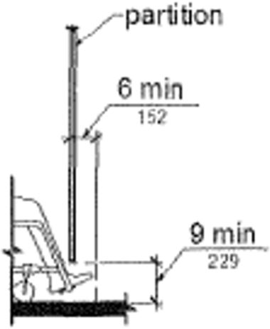
(a) elevation adult
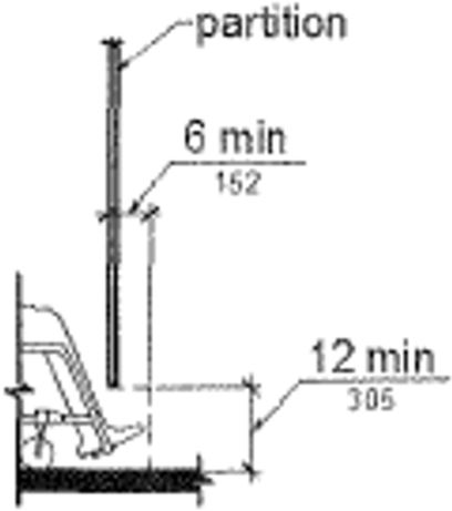
(b) elevation children
(c) plan
FIGURE 11B-604.8.1.4 WHEELCHAIR ACCESSIBLE TOILET COMPARTMENT TOE CLEARANCE ‡‡
11B-604.8.1.5 Grab bars.
Grab bars shall comply with Section 11B-609. A side-wall grab bar complying with Section 11B-604.5.1 shall be provided and shall be located on the wall closest to the water closet. In addition, a rear-wall grab bar complying with Section 11B-604.5.2 shall be provided. Where separate grab bars are required on adjacent walls at a common mounting height, an L-shaped grab bar meeting the dimensional requirements of Sections 11B-604.5.1 and 11B-604.5.2 shall be permitted.
[2010 ADA Standards] 604.8.1.5 Grab Bars. Grab bars shall comply with 609. A side-wall grab bar complying with 604.5.1 shall be provided and shall be located on the wall closest to the water closet. In addition, a rear-wall grab bar complying with 604.5.2 shall be provided.
11B-604.8.2 Ambulatory accessible compartments.
Ambulatory accessible compartments shall comply with Section 11B-604.8.2.
11B-604.8.2.1 Size.
Ambulatory accessible compartments shall have a depth of 60 inches (1524 mm) minimum and a width of 35 inches (889 mm) minimum and 37 inches (940 mm) maximum.
11B-604.8.2.2 Doors.
Toilet compartment doors, including door hardware, shall comply with Section 11B-404, except that if the approach is to the latch side of the compartment door, clearance between the door side of the compartment and any obstruction shall be 44 inches (1118 mm) minimum. The door shall be self-closing. A door pull complying with Section 11B-404.2.7 shall be placed on both sides of the door near the latch. Toilet compartment doors shall not swing into the minimum required compartment area.
[2010 ADA Standards] 604.8.2.2 Doors. Toilet compartment doors, including door hardware, shall comply with 404, except that if the approach is to the latch side of the compartment door, clearance between the door side of the compartment and any obstruction shall be 42 inches (1065 mm) minimum. The door shall be self-closing. A door pull complying with 404.2.7 shall be placed on both sides of the door near the latch. Toilet compartment doors shall not swing into the minimum required compartment area.
11B-604.8.2.3 Grab bars.
Grab bars shall comply with Section 11B-609. A side-wall grab bar complying with Section 11B-604.5.1 shall be provided on both sides of the compartment.
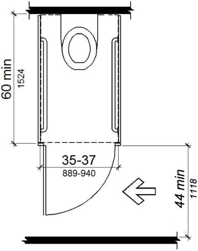
FIGURE 11B-604.8.2 AMBULATORY ACCESSIBLE TOILET COMPARTMENT ‡‡
11B-604.8.3 Coat hooks and shelves.
Coat hooks shall be located within one of the reach ranges specified in Section 11B-308. Shelves shall be located 40 inches (1016 mm) minimum and 48 inches (1219 mm) maximum above the finish floor.
11B-604.9 Water closets and toilet compartments for children's use.
Water closets and toilet compartments for children's use shall comply with Section 11B-604.9. When the exception in Section 11B-604.1 is used, the suggested dimensions of Table 11B-604.9 for a single age group shall be applied consistently to the installation of a water closet and all associated components.

TABLE 11B-604.9 SUGGESTED DIMENSIONS FOR CHILDREN’S USE
|
Suggested Dimensions For Water Closets Serving Children Ages 3 Through 12 |
|||
|---|---|---|---|
| Ages 3 and 4 | Ages 5 through 8 |
Ages 9 through 12 |
|
|
Water Closet Centerline |
12 inches (305 mm) |
12 to 15 inches (305 to 381 mm) |
15 to 18 inches (381 to 457 mm) |
|
Toilet Seat Height |
11 to 12 inches (279 to 305 mm) | 12 to 15 inches (305 to 381 mm) |
15 to 17 inches (381 to 432 mm) |
|
Grab Bar Height |
18 to 20 inches (457 to 508 mm) | 20 to 25 inches (508 to 635 mm) |
25 to 27 inches (635 to 686 mm) |
|
Dispenser Height |
14 inches (356 mm) | 14 to 17 inches (356 to 432 mm) |
17 to 19 inches (432 to 483 mm) |
11B-604.9.1 Location.
The water closet shall be located with a wall or partition to the rear and to one side. The centerline of the water closet shall be 12 inches (305 mm) minimum and 18 inches (457 mm) maximum from the side wall or partition, except that the water closet shall be 17 inches (432 mm) minimum and 19 inches (483 mm) maximum from the side wall or partition in the ambulatory accessible toilet compartment specified in Section 11B-604.8.2. Compartments shall be arranged for left-hand or right-hand approach to the water closet.
11B-604.9.2 Clearance.
Clearance around a water closet shall comply with Section 11B-604.3.
11B-604.9.3 Height.
The height of water closets shall be 11 inches (279 mm) minimum and 17 inches (432 mm) maximum measured to the top of the seat. Seats shall not be sprung to return to a lifted position.
11B-604.9.4 Grab bars.
Grab bars for water closets shall comply with Section 11B-604.5.
11B-604.9.5 Flush controls.
Flush controls shall be hand operated or automatic. Hand operated flush controls shall comply with Sections 11B-309.2 and 11B-309.4 and shall be installed 36 inches (914 mm) maximum above the finish floor. Flush controls shall be located on the open side of the water closet except in ambulatory accessible compartments complying with Section 11B-604.8.2.
11B-604.9.6 Dispensers.
Toilet paper dispensers shall comply with Section 11B-309.4 and shall be 7 inches (178 mm) minimum and 9 inches (229 mm) maximum in front of the water closet measured to the centerline of the dispenser. The outlet of the dispenser shall be 14 inches (356 mm) minimum and 19 inches (483 mm) maximum above the finish floor. There shall be a clearance of 1½ inches (38 mm) minimum below the grab bar. Dispensers shall not be of a type that controls delivery or that does not allow continuous paper flow.
11B-604.9.7 Toilet Compartments.
Toilet compartments shall comply with Section 11B-604.8.
11B-605.1 General.
Urinals shall comply with Section 11B-605.

11B-605.2 Height and depth.
Urinals shall be the stall-type or the wall-hung type with the rim 17 inches (432 mm) maximum above the finish floor or ground. Urinals shall be 13½ inches (343 mm) deep minimum measured from the outer face of the urinal rim to the back of the fixture.
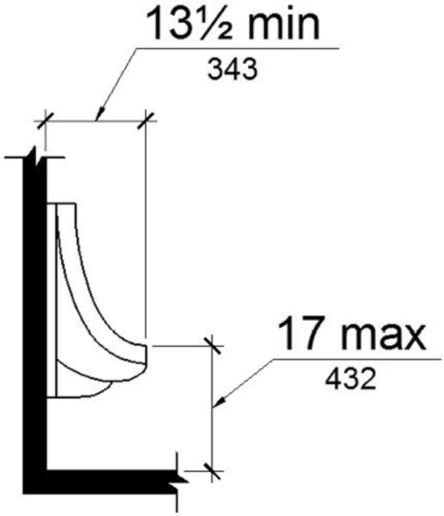
(a) wall hung type
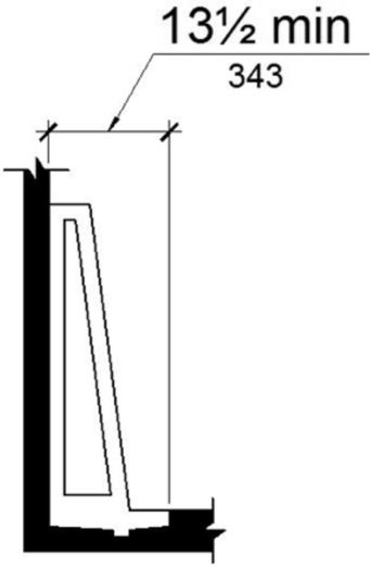
(b) stall type
FIGURE 11B-605.2 HEIGHT AND DEPTH OF URINALS
11B-605.3 Clear floor space.
A clear floor or ground space complying with Section 11B-305 positioned for forward approach shall be provided.
11B-605.4 Flush controls.
Flush controls shall be hand operated or automatic. Hand operated flush controls shall comply with Section 11B-309 except that the flush control shall be mounted at a maximum height of 44 inches (1118 mm) above the finish floor.
[2010 ADA Standards] 605.4 Flush Controls. Flush controls shall be hand operated or automatic. Hand operated flush controls shall comply with 309.
11B-606.1 General.
Lavatories and sinks shall comply with Section 11B-606.

11B-606.2 Clear floor space.
A clear floor space complying with Section 11B-305, positioned for a forward approach, and knee and toe clearance complying with Section 11B-306 shall be provided.
Exceptions:
1. A parallel approach complying with Section 11B-305 shall be permitted to a kitchen sink in a space where a cook top or conventional range is not provided and to wet bars.
2. Reserved.
[2010 ADA Standards] 2. A lavatory in a toilet room or bathing facility for a single occupant accessed only through a private office and not for common use or public use shall not be required to provide knee and toe clearance complying with 306.
3. In residential dwelling units, cabinetry shall be permitted under lavatories and kitchen sinks provided that all of the following conditions are met:
(a) the cabinetry can be removed without removal or replacement of the fixture;
(b) the finish floor extends under the cabinetry; and
(c) the walls behind and surrounding the cabinetry are finished.
4. A knee clearance of 24 inches (610 mm) minimum above the finish floor or ground shall be permitted at lavatories and sinks used primarily by children 6 through 12 years where the rim or counter surface is 31 inches (787 mm) maximum above the finish floor or ground.
5. A parallel approach complying with Section 11B-305 shall be permitted to lavatories and sinks used primarily by children 5 years and younger.
6. The dip of the overflow shall not be considered in determining knee and toe clearances.
7. No more than one bowl of a multi-bowl sink shall be required to provide knee and toe clearance complying with Section 11B-306.
11B-606.3 Height.
Lavatories and sinks shall be installed with the front of the higher of the rim or counter surface 34 inches (864 mm) maximum above the finish floor or ground.
ETA Editor's Note
Top-mounted sinks installed in counters having the top surface 34 inches above the floor will exceed the maximum rim height allowed, regardless of how thin the flange may be.
Exceptions:
1. Reserved.
[2010 ADA Standards] 1. A lavatory in a toilet or bathing facility for a single occupant accessed only through a private office and not for common use or public use shall not be required to comply with 606.3.
2. In residential dwelling unit kitchens, sinks that are adjustable to variable heights, 29 inches (737 mm) minimum and 36 inches (914 mm) maximum, shall be permitted where rough-in plumbing permits connections of supply and drain pipes for sinks mounted at the height of 29 inches (737 mm).
11B-606.4 Faucets.
Controls for faucets shall comply with Section 11B-309. Hand-operated metering faucets shall remain open for 10 seconds minimum.
11B-606.5 Exposed pipes and surfaces.
Water supply and drain pipes under lavatories and sinks shall be insulated or otherwise configured to protect against contact. There shall be no sharp or abrasive surfaces under lavatories and sinks.
11B-606.6 Adjacent side wall or partition.
Lavatories, when located adjacent to a side wall or partition, shall be a minimum of 18 inches (457 mm) to the centerline of the fixture.
ETA Editor's Note
The positioning requirement prescribed by CBC 11B-606.6 applies to lavatories, not to sinks. However, some Local Building Officials or other Authorities Having Jurisdiction may apply it to both. See the foregoing ETA Editor's Note at 11B-212.3 regarding the difficulties of distinguishing fixture types and the applicable technical requirements.
11B-606.7 Sink depth.
Where a forward approach is required at a sink, knee and toe clearance shall be provided in compliance with Section 11B-306.
11B-607.1 General.
Bathtubs shall comply with Section 11B-607.
11B-607.2 Clearance.
Clearance in front of bathtubs shall extend the length of the bathtub and shall be 48 inches (1219 mm) wide minimum for forward approach and 30 inches (762 mm) wide minimum for parallel approach. A lavatory complying with Section 11B-606 shall be permitted at the control end of the clearance. Where a permanent seat is provided at the head end of the bathtub, the clearance shall extend 12 inches (305 mm) minimum beyond the wall at the head end of the bathtub.
[2010 ADA Standards] 607.2 Clearance. Clearance in front of bathtubs shall extend the length of the bathtub and shall be 30 inches (760 mm) wide minimum. A lavatory complying with 606 shall be permitted at the control end of the clearance. Where a permanent seat is provided at the head end of the bathtub, the clearance shall extend 12 inches (305 mm) minimum beyond the wall at the head end of the bathtub.
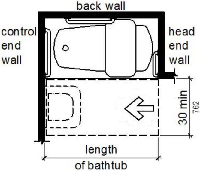
(a) removable in-tub seat
parallel approach
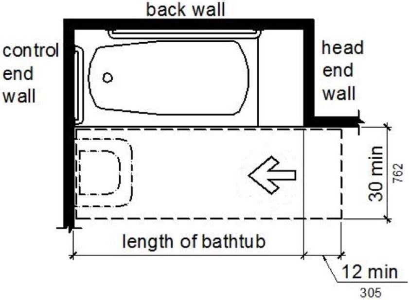
(b) permanent seat
parallel approach
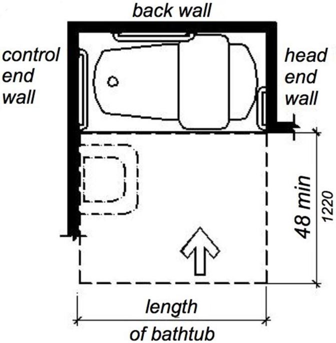
(c) removable in-tub seat
forward approach
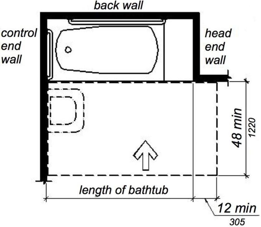
(d) permanent seat
forward approach
FIGURE 11B-607.2 CLEARANCE FOR BATHTUBS ‡‡
11B-607.3 Seat.
A permanent seat at the head end of the bathtub or a removable in-tub seat shall be provided. Seats shall comply with Section 11B-610.
11B-607.4 Grab bars.
Grab bars for bathtubs shall comply with Section 11B-609 and shall be provided in accordance with Section 11B-607.4.1 or 11B-607.4.2. Where separate grab bars are required on adjacent walls at a common mounting height, an L-shaped or U-shaped grab bar meeting the dimensional requirements of Section 11B-607.4.1 or 11B-607.4.2 shall be permitted.
[2010 ADA Standards] 607.4 Grab Bars. Grab bars for bathtubs shall comply with 609 and shall be provided in accordance with 607.4.1 or 607.4.2.
Exceptions:
1. Reserved.
[2010 ADA Standards] 1. Grab bars shall not be required to be installed in a bathtub located in a bathing facility for a single occupant accessed only through a private office and not for common use or public use provided that reinforcement has been installed in walls and located so as to permit the installation of grab bars complying with 607.4.
2. In residential dwelling units, grab bars shall not be required to be installed in bathtubs located in bathing facilities provided that reinforcement has been installed in walls and located so as to permit the installation of grab bars complying with Section 11B-607.4.
11B-607.4.1 Bathtubs with permanent seats.
For bathtubs with permanent seats, grab bars shall be provided in accordance with Section 11B-607.4.1.
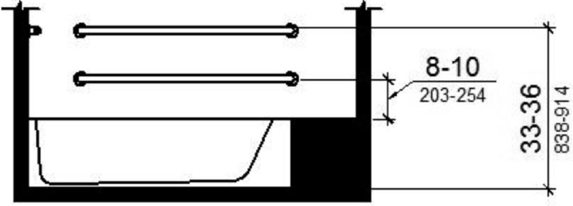
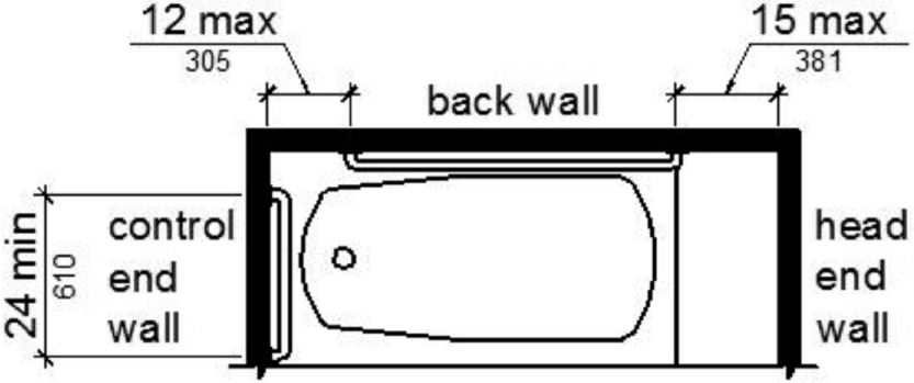
11B-607.4.1.1 Back wall.
Two grab bars shall be installed on the back wall, one located in accordance with Section 11B-609.4 and the other located 8 inches (203 mm) minimum and 10 inches (254 mm) maximum above the rim of the bathtub. Each grab bar shall be installed 15 inches (381 mm) maximum from the head end wall and 12 inches (305 mm) maximum from the control end wall.
11B-607.4.1.2 Control end wall.
A grab bar 24 inches (610 mm) long minimum shall be installed on the control end wall at the front edge of the bathtub.
(a) elevation
(b) plan
FIGURE 11B-607.4.1 GRAB BARS FOR BATHTUBS WITH PERMANENT SEATS
11B-607.4.2 Bathtubs without permanent seats.
For bathtubs without permanent seats, grab bars shall comply with Section 11B-607.4.2.
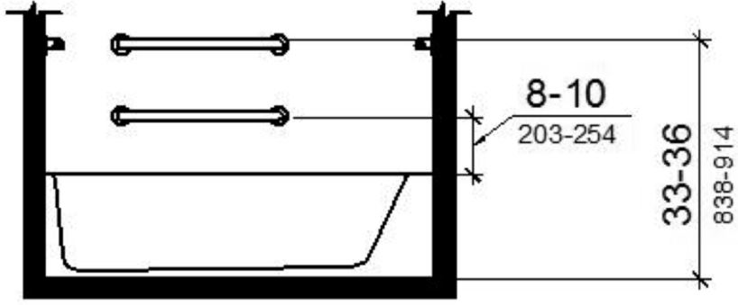
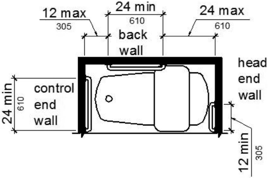
11B-607.4.2.1 Back wall.
Two grab bars shall be installed on the back wall, one located in accordance with Section 11B-609.4 and the other located 8 inches (203 mm) minimum and 10 inches (254 mm) maximum above the rim of the bathtub. Each grab bar shall be 24 inches (610 mm) long minimum and shall be installed 24 inches (610 mm) maximum from the head end wall and 12 inches (305 mm) maximum from the control end wall.
11B-607.4.2.2 Control end wall.
A grab bar 24 inches (610 mm) long minimum shall be installed on the control end wall at the front edge of the bathtub.
11B-607.4.2.3 Head end wall.
A grab bar 12 inches (305 mm) long minimum shall be installed on the head end wall at the front edge of the bathtub.
(a) elevation
(b) plan
FIGURE 11B-607.4.2 GRAB BARS FOR BATHTUBS WITH REMOVABLE IN-TUB SEATS
11B-607.5 Controls.
Controls, other than drain stoppers, shall be located on an end wall. Controls shall be between the bathtub rim and grab bar, and between the open side of the bathtub and the centerline of the width of the bathtub. Controls shall comply with Section 11B-309.4.
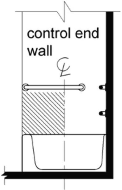
FIGURE 11B-607.5 BATHTUB CONTROL LOCATION
11B-607.6 Shower spray unit and water.
A shower spray unit with a hose 59 inches (1499 mm) long minimum that can be used both as a fixed-position shower head and as a hand-held shower shall be provided. The shower spray unit shall have an on/off control with a non-positive shut-off. If an adjustable-height shower head on a vertical bar is used, the bar shall be installed so as not to obstruct the use of grab bars. Bathtub shower spray units shall deliver water that is 120°F (49°C) maximum.

11B-607.7 Bathtub enclosures.
Enclosures for bathtubs shall not obstruct controls, faucets, shower and spray units or obstruct transfer from wheelchairs onto bathtub seats or into bathtubs. Enclosures on bathtubs shall not have tracks installed on the rim of the open face of the bathtub.
11B-608.1 General.
Shower compartments shall comply with Section 11B-608.

11B-608.2 Size and clearances for shower compartments.
Shower compartments shall have sizes and clearances complying with Section 11B-608.2.
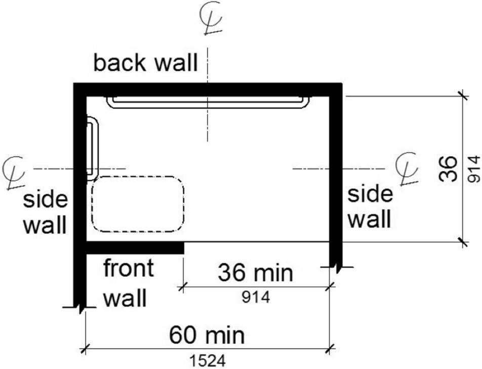
11B-608.2.1 Transfer type shower compartments.
Transfer type shower compartments shall be 36 inches (914 mm) by 36 inches (914 mm) clear inside dimensions measured at the center points of opposing sides and shall have a 36 inch (914 mm) wide minimum entry on the face of the shower compartment. Clearance of 36 inches (914 mm) wide minimum by 48 inches (1219 mm) long minimum measured from the control wall shall be provided. Transfer type shower compartments shall be permitted in transient lodging guest rooms, multibedroom housing units in undergraduate student housing and residential dwelling units; and shall not be permitted at other locations to meet the requirements of Section 11B-213.3.6.
[2010 ADA Standards] 608.2.1 Transfer Type Shower Compartments. Transfer type shower compartments shall be 36 inches (915 mm) by 36 inches (915 mm) clear inside dimensions measured at the center points of opposing sides and shall have a 36 inch (915 mm) wide minimum entry on the face of the shower compartment. Clearance of 36 inches (915 mm) wide minimum by 48 inches (1220 mm) long minimum measured from the control wall shall be provided.
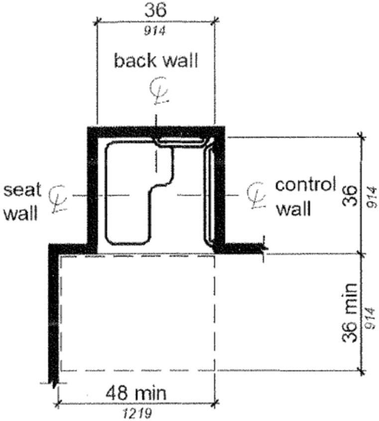
FIGURE 11B-608.2.1 TRANSFER TYPE SHOWER COMPARTMENT SIZE AND CLEARANCE
11B-608.2.2 Standard roll-in type shower compartments.
Standard roll-in type shower compartments shall be 30 inches (762 mm) wide minimum by 60 inches (1524 mm) deep minimum clear inside dimensions measured at center points of opposing sides with a full opening width on the long side.
[2010 ADA Standards] 608.2.2 Standard Roll-In Type Shower Compartments. Standard roll-in type shower compartments shall be 30 inches (760 mm) wide minimum by 60 inches (1525 mm) deep minimum clear inside dimensions measured at center points of opposing sides and shall have a 60 inches (1525 mm) wide minimum entry on the face of the shower compartment.
11B-608.2.2.1 Clearance.
A 36 inch (914 mm) wide minimum by 60 inch (1524 mm) long minimum clearance shall be provided adjacent to the open face of the shower compartment.
[2010 ADA Standards] 608.2.2.1 Clearance. A 30 inch (760 mm) wide minimum by 60 inch (1525 mm) long minimum clearance shall be provided adjacent to the open face of the shower compartment.
Exception: Reserved.
[2010 ADA Standards] EXCEPTION: A lavatory complying with 606 shall be permitted on one 30 inch (760 mm) wide minimum side of the clearance provided that it is not on the side of the clearance adjacent to the controls or, where provided, not on the side of the clearance adjacent to the shower seat.
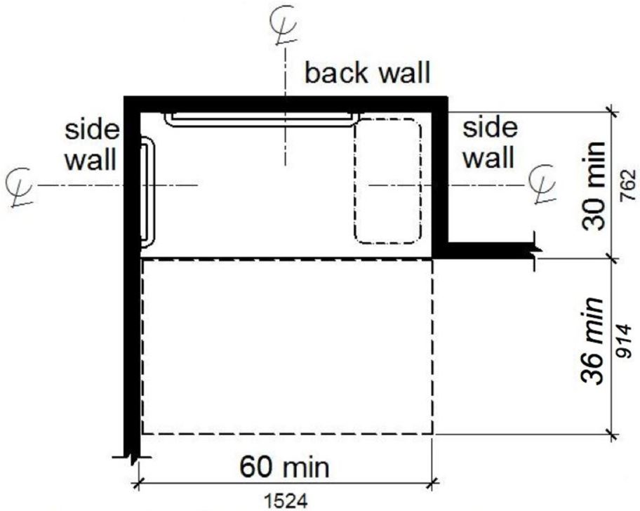
Note: inside finished dimensions measured at the center points of opposing sides.
FIGURE 11B-608.2.2 STANDARD ROLL-IN TYPE SHOWER COMPARTMENT SIZE AND CLEARANCE ‡‡
11B-608.2.3 Alternate roll-in type shower compartments.
Alternate roll-in type shower compartments shall be 36 inches (914 mm) wide and 60 inches (1524 mm) deep minimum clear inside dimensions measured at center points of opposing sides. A 36 inch (914 mm) wide minimum entry shall be provided at one end of the long side of the compartment.
Note: inside finished dimensions measured at the center points of opposing sides.
FIGURE 11B-608.2.3 ALTERNATE ROLL-IN TYPE SHOWER COMPARTMENT SIZE AND CLEARANCE
11B-608.3 Grab bars.
Grab bars shall comply with Section 11B-609 and shall be provided in accordance with Section 11B-608.3. Where multiple grab bars are used, required horizontal grab bars shall be installed at the same height above the finish floor. Where separate grab bars are required on adjacent walls at a common mounting height, an L-shaped or U-shaped grab bar meeting the dimensional requirements of Section 11B-608.3.2 or 11B-608.3.3 shall be permitted.
[2010 ADA Standards] 608.3 Grab Bars. Grab bars shall comply with 609 and shall be provided in accordance with 608.3. Where multiple grab bars are used, required horizontal grab bars shall be installed at the same height above the finish floor.
Exceptions:
1. Reserved.
[2010 ADA Standards] 1. Grab bars shall not be required to be installed in a shower located in a bathing facility for a single occupant accessed only through a private office, and not for common use or public use provided that reinforcement has been installed in walls and located so as to permit the installation of grab bars complying with 608.3.
2. In residential dwelling units, grab bars shall not be required to be installed in showers located in bathing facilities provided that reinforcement has been installed in walls and located so as to permit the installation of grab bars complying with Section 11B-608.3.
11B-608.3.1 Transfer type shower compartments.
In transfer type compartments, grab bars shall be provided across the control wall and back wall to a point 18 inches (457 mm) from the control wall.
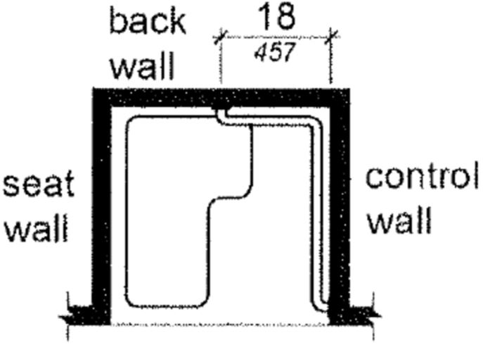
FIGURE 11B-608.3.1 GRAB BARS FOR TRANSFER TYPE SHOWERS
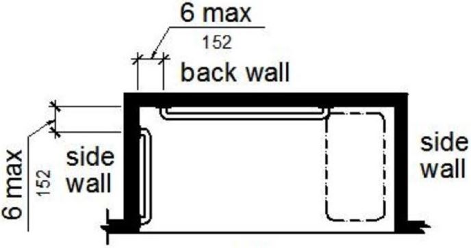
11B-608.3.2 Standard roll-in type shower compartments.
Grab bars shall be provided on the back wall and the side wall opposite the seat. Grab bars shall not be provided above the seat. Grab bars shall be installed 6 inches (152 mm) maximum from adjacent walls.
[2010 ADA Standards] 608.3.2 Standard Roll-In Type Shower Compartments. Where a seat is provided in standard roll-in type shower compartments, grab bars shall be provided on the back wall and the side wall opposite the seat. Grab bars shall not be provided above the seat. Where a seat is not provided in standard roll-in type shower compartments, grab bars shall be provided on three walls. Grab bars shall be installed 6 inches (150 mm) maximum from adjacent walls.
(a) reserved
(b) with seat
FIGURE 11B-608.3.2 GRAB BARS FOR STANDARD ROLL-IN TYPE SHOWER ‡‡
11B-608.3.3 Alternate roll-in type shower compartments.
In alternate roll-in type shower compartments, grab bars shall be provided on the back wall and the side wall farthest from the compartment entry. Grab bars shall not be provided above the seat. Grab bars shall be installed 6 inches (152 mm) maximum from adjacent walls.
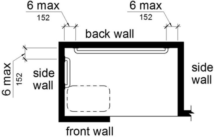
FIGURE 11B-608.3.3 GRAB BARS FOR ALTERNATE ROLL-IN TYPE SHOWERS
11B-608.4 Seats.
A folding seat shall be provided in roll-in type showers and transfer type shower compartments. Seats shall comply with Section 11B-610.
[2010 ADA Standards] 608.4 Seats. A folding or non-folding seat shall be provided in transfer type shower compartments. A folding seat shall be provided in roll-in type showers required in transient lodging guest rooms with mobility features complying with 806.2. Seats shall comply with 610.
Exception: In residential dwelling units, seats shall not be required in shower compartments provided that reinforcement has been installed in walls so as to permit the installation of seats complying with Section 11B-608.4.
ETA Editor's Note
Unlike 2010 ADA Standards, CBC requires a folding seat at all accessible showers, unless the Exception above is applicable.
11B-608.5 Controls.
Controls, faucets, and shower spray units shall comply with Section 11B-309.4. Controls and faucets shall allow the user to close and open the water supply.
[2010 ADA Standards] 608.5 Controls. Controls, faucets, and shower spray units shall comply with 309.4.
11B-608.5.1 Transfer type shower compartments.
In transfer type shower compartments, the controls, faucets, and shower spray unit shall be installed on the side wall opposite the seat 38 inches (965 mm) minimum and 48 inches (1219 mm) maximum above the shower floor and shall be located on the control wall 15 inches (380 mm) maximum from the centerline of the seat toward the shower opening.
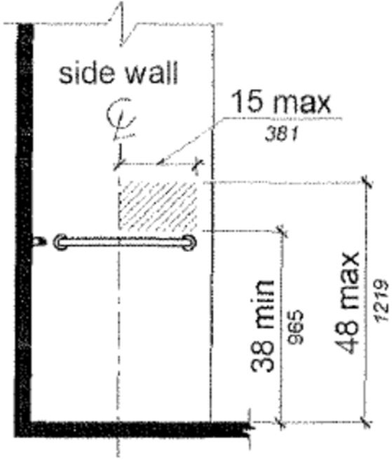
FIGURE 11B-608.5.1 TRANSFER TYPE SHOWER COMPARTMENT CONTROL LOCATION
11B-608.5.2 Standard roll-in type shower compartments.
In standard roll-in type shower compartments, the controls, faucets, and the shower spray unit shall be located on the back wall of the compartment adjacent to the seat 16 inches (406 mm) minimum and 27 inches (686 mm) maximum from the seat wall; and shall be located above the grab bar, but no higher than 48 inches (1219 mm) above the shower floor.
[2010 ADA Standards] 608.5.2 Standard Roll-In Type Shower Compartments. In standard roll-in type shower compartments, the controls, faucets, and shower spray unit shall be located above the grab bar, but no higher than 48 inches (1220 mm) above the shower floor. Where a seat is provided, the controls, faucets, and shower spray unit shall be installed on the back wall adjacent to the seat wall and shall be located 27 inches (685 mm) maximum from the seat wall.
(a) reserved
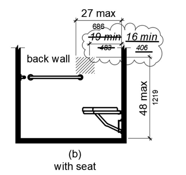
(b) with seat
FIGURE 11B-608.5.2
STANDARD ROLL-IN TYPE SHOWER COMPARTMENT CONTROL LOCATION
ETA Editor's Note
The CBC requirements for positioning controls in standard roll-in shower compartments are more restrictive than 2010 ADA Standards.
11B-608.5.3 Alternate roll-in type shower compartments.
In alternate roll-in type shower compartments, the controls, faucets, and shower spray unit shall be located on the side wall of the compartment adjacent to the 16 inches (406 mm) minimum and 27 inches (686 mm) maximum from the seat wall or shall be located on the back wall opposite the seat 15 inches (381 mm) maximum, left or right of the centerline of the seat. The controls, faucets, and shower spray units shall be located above the grab bar, but no higher than 48 inches (1219 mm) above the shower floor.
[2010 ADA Standards] 608.5.3 Alternate Roll-In Type Shower Compartments. In alternate roll-in type shower compartments, the controls, faucets, and shower spray unit shall be located above the grab bar, but no higher than 48 inches (1220 mm) above the shower floor. Where a seat is provided, the controls, faucets, and shower spray unit shall be located on the side wall adjacent to the seat 27 inches (685 mm) maximum from the side wall behind the seat or shall be located on the back wall opposite the seat 15 inches (380 mm) maximum, left or right, of the centerline of the seat. Where a seat is not provided, the controls, faucets, and shower spray unit shall be installed on the side wall farthest from the compartment entry.
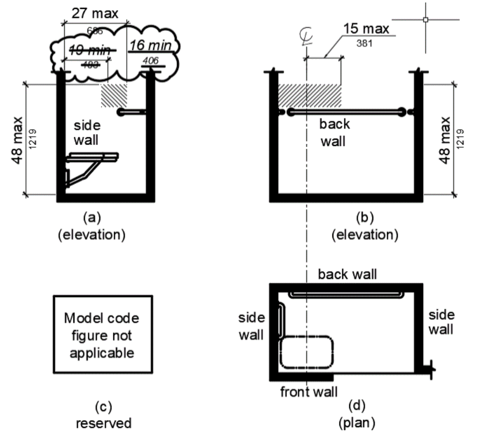
FIGURE 11B-608.5.3
ALTERNATE ROLL-IN TYPE SHOWER COMPARTMENT CONTROL LOCATION
ETA Editor's Note
The CBC requirements for positioning controls in alternate roll-in shower compartments are more restrictive than 2010 ADA Standards.
11B-608.6 Shower spray unit and water.
A shower spray unit with a hose 59 inches (1499 mm) long minimum that can be used both as a fixed-position shower head and as a hand-held shower shall be provided. The shower spray unit shall have an on/off control with a non-positive shut-off. If an adjustable-height shower head on a vertical bar is used, the bar shall be installed so as not to obstruct the use of grab bars. Shower spray units shall deliver water that is 120°F (49°C) maximum.
Exception: Where subject to excessive vandalism, two fixed shower heads shall be permitted instead of a hand-held spray unit in facilities that are not medical care facilities, long-term care facilities, transient lodging guest rooms, or residential dwelling units. Each shower head shall be installed so it can be operated independently of the other and shall have swivel angle adjustments, both vertically and horizontally. One shower head shall be located at a height of 48 inches (1219 mm) maximum above the shower finish floor.
[2010 ADA Standards] EXCEPTION: A fixed shower head located at 48 inches (1220 mm) maximum above the shower finish floor shall be permitted instead of a hand-held spray unit in facilities that are not medical care facilities, long-term care facilities, transient lodging guest rooms, or residential dwelling units.

The 2010 ADA Standards Exception at 608.6 does not require the consideration of excessive vandalism or the installation of two shower heads where fixed ones are provided. Therefore, the CBC requirements are more stringent.
11B-608.7 Thresholds.
Thresholds in roll-in type shower compartments shall be ½ inch (12.7 mm) high maximum in accordance with Section 11B-303. In transfer type shower compartments, thresholds ½ inch (12.7 mm) high maximum shall be beveled, rounded, or vertical.
Exception: A threshold 2 inches (51 mm) high maximum shall be permitted in transfer type shower compartments in existing facilities where provision of a ½ inch (12.7 mm) high threshold would disturb the structural reinforcement of the floor slab.
11B-608.8 Shower enclosures.
Enclosures for shower compartments shall not obstruct controls, faucets, and shower spray units or obstruct transfer from wheelchairs onto shower seats.
11B-608.9 Shower floor or ground surface.
Floor or ground surfaces of showers shall comply with Section 11B-302.1 and shall be sloped 1:48 maximum in any direction. Where drains are provided, grate openings shall be ¼ inch (6.4 mm) maximum and flush with the floor surface.
11B-608.10 Soap dish.
Where a soap dish is provided, it shall be located on the control wall at 40 inches (1016 mm) maximum above the shower floor, and within the reach limits from the seat.
11B-609.1 General.
Grab bars in toilet facilities and bathing facilities shall comply with Section 11B-609.
11B-609.2 Cross section.
Grab bars shall have a cross section complying with Section 11B-609.2.1 or 11B-609.2.2.
11B-609.2.1 Circular cross section.
Grab bars with circular cross sections shall have an outside diameter of 1¼ inches (32 mm) minimum and 2 inches (51 mm) maximum.
11B-609.2.2 Non-circular cross section.
Grab bars with non-circular cross sections shall have a cross-section dimension of 2 inches (51 mm) maximum and a perimeter dimension of 4 inches (102 mm) minimum and 4.8 inches (122 mm) maximum.
FIGURE 11B-609.2.2 GRAB BAR NON-CIRCULAR CROSS SECTION
11B-609.3 Spacing.
The space between the wall and the grab bar shall be 1½ inches (38 mm). The space between the grab bar and projecting objects below and at the ends shall be 1½ inches (38 mm) minimum. The space between the grab bar and projecting objects above shall be 12 inches (305 mm) minimum.
Exceptions:
- The space between the grab bars and shower controls, shower fittings, and other grab bars above shall be permitted to be 1½ inches (38 mm) minimum.
- For L-shaped or U-shaped grab bars complying with Section 11B-609.9 the space between the walls and the grab bar shall be 1½ inches (38 mm) minimum for a distance of 6 inches on either side of the inside corner between two adjacent wall surfaces.

(a) projecting objects
(b) recessed objects
FIGURE 11B-609.3 SPACING OF GRAB BARS
11B-609.4 Position of grab bars.
Grab bars shall be installed in a horizontal position, 33 inches (838 mm) minimum and 36 inches (914 mm) maximum above the finish floor measured to the top of the gripping surface, except that at water closets for children's use complying with Section 11B-604.9, grab bars shall be installed in a horizontal position 18 inches (457 mm) minimum and 27 inches (686 mm) maximum above the finish floor measured to the top of the gripping surface. The height of the lower grab bar on the back wall of a bathtub shall comply with Section 11B-607.4.1.1 or 11B-607.4.2.1.
11B-609.5 Surface hazards.
Grab bars and any wall or other surfaces adjacent to grab bars shall be free of sharp or abrasive elements and shall have rounded edges.
11B-609.7 Installation.
Grab bars shall be installed in any manner that provides a gripping surface at the specified locations and that does not obstruct the required clear floor space.
11B-609.8 Structural strength.
Allowable stresses shall not be exceeded for materials used when a vertical or horizontal force of 250 pounds (1112 N) is applied at any point on the grab bar, fastener, mounting device, or supporting structure.
11B-610.1 General.
Seats in bathtubs and shower compartments shall comply with Section 11B-610.
11B-610.2 Bathtub seats.
The top of bathtub seats shall be 17 inches (432 mm) minimum and 19 inches (483 mm) maximum above the bathroom finish floor. The depth of a removable in-tub seat shall be 15 inches (381 mm) minimum and 16 inches (406 mm) maximum. The seat shall be capable of secure placement. Permanent seats at the head end of the bathtub shall be 15 inches (381 mm) deep minimum and shall extend from the back wall to or beyond the outer edge of the bathtub.
FIGURE 11B-610.2 BATHTUB SEATS
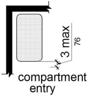
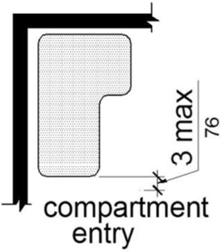
11B-610.3 Shower compartment seats.
A seat in a standard roll-in shower compartment shall be a folding type, shall be installed on the side wall adjacent to the controls, and shall extend from the back wall to a point within 3 inches (76 mm) of the compartment entry. A seat in an alternate roll-in type shower compartment shall be a folding type, shall be installed on the front wall opposite the back wall, and shall extend from the adjacent side wall to a point within 3 inches (76 mm) of the compartment entry. In transfer-type showers, the seat shall extend from the back wall to a point within 3 inches (76 mm) of the compartment entry. The top of the seat shall be 17 inches (432 mm) minimum and 19 inches (483 mm) maximum above the bathroom finish floor. When folded, the seat shall extend 6 inches (152 mm) maximum from the mounting wall. Seats shall comply with Section 11B-610.3.1 or 11B-610.3.2.
[2010 ADA Standards] 610.3 Shower Compartment Seats. Where a seat is provided in a standard roll-in shower compartment, it shall be a folding type, shall be installed on the side wall adjacent to the controls, and shall extend from the back wall to a point within 3 inches (75 mm) of the compartment entry. Where a seat is provided in an alternate roll-in type shower compartment, it shall be a folding type, shall be installed on the front wall opposite the back wall, and shall extend from the adjacent side wall to a point within 3 inches (75 mm) of the compartment entry. In transfer-type showers, the seat shall extend from the back wall to a point within 3 inches (75 mm) of the compartment entry. The top of the seat shall be 17 inches (430 mm) minimum and 19 inches (485 mm) maximum above the bathroom finish floor. Seats shall comply with 610.3.1 or 610.3.2.
(a) rectangular
(b) L-shaped
FIGURE 11B-610.3 EXTENT OF SEAT
11B-610.3.1 Rectangular seats.
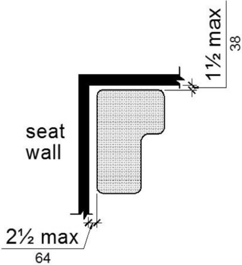
The rear edge of a rectangular seat shall be 2½ inches (64 mm) maximum and the front edge 15 inches (381 mm) minimum and 16 inches (406 mm) maximum from the seat wall. The side edge of the seat shall be 1½ inches (38 mm) maximum from the adjacent wall.
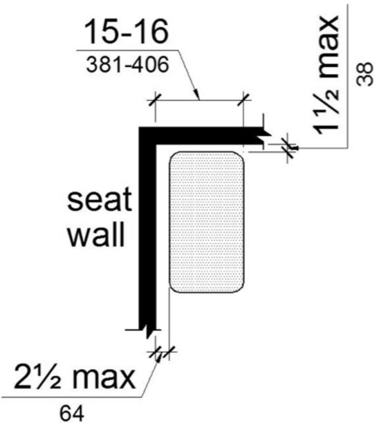
FIGURE 11B-610.3.1 RECTANGULAR SHOWER SEAT
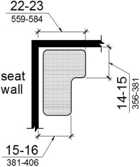
11B-610.3.2 L-shaped seats.
The rear edge of an L-shaped seat shall be 2½ inches (64 mm) maximum and the front edge 15 inches (381 mm) minimum and 16 inches (406 mm) maximum from the seat wall. The rear edge of the “L” portion of the seat shall be 1½ inches (38 mm) maximum from the wall and the front edge shall be 14 inches (356 mm) minimum and 15 inches (381 mm) maximum from the wall. The end of the “L” shall be 22 inches (559 mm) minimum and 23 inches (584 mm) maximum from the main seat wall.
(a) size
(b) distance from wall
FIGURE 11B-610.3.2 L-SHAPED SHOWER SEAT
11B-610.4 Structural strength.
Allowable stresses shall not be exceeded for materials used when a vertical or horizontal force of 250 pounds (1112 N) is applied at any point on the seat, fastener, mounting device, or supporting structure.
11B-611.1 General.
Washing machines and clothes dryers shall comply with Section 11B-611.
11B-611.2 Clear Floor Space.
A clear floor or ground space complying with Section 11B-305 positioned for parallel approach shall be provided. The clear floor or ground space shall be centered on the appliance.
11B-611.3 Operable parts.
Operable parts, including doors, lint screens, and detergent and bleach compartments shall comply with Section 11B-309.
11B-611.4 Height.
Top loading machines shall have the door to the laundry compartment located 36 inches (914 mm) maximum above the finish floor. Front loading machines shall have the bottom of the opening to the laundry compartment located 15 inches (381 mm) minimum and 36 inches (914 mm) maximum above the finish floor.
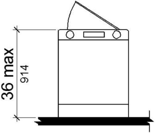
(a) top loading
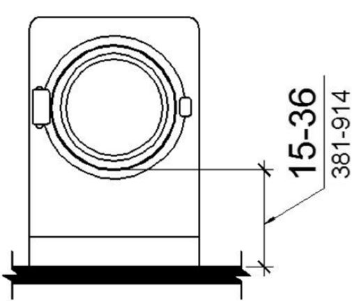
(b) front loading
FIGURE 11B-611.4 HEIGHT OF LAUNDRY COMPARTMENT OPENING
11B-612.1 General.
Saunas and steam rooms shall comply with Section 11B-612.
11B-612.2 Bench.
Where seating is provided in saunas and steam rooms, at least one bench shall comply with Section 11B-903. Doors shall not swing into the clear floor space required by Section 11B-903.2.
Exception: A readily removable bench shall be permitted to obstruct the turning space required by Section 11B-612.3 and the clear floor or ground space required by Section 11B-903.2.
11B-612.3 Turning space.
A turning space complying with Section 11B-304 shall be provided within saunas and steam rooms.
User Comments/Questions
Add Comment/Question