4. ACCESSIBLE ELEMENTS AND SPACES: SCOPE AND TECHNICAL REQUIREMENTS.
4.1 MINIMUM REQUIREMENTS.
4.1.1 ACCESSIBLE SITES AND EXTERIOR FACILITIES: NEW CONSTRUCTION.
An accessible site shall meet the following minimum requirements:
(1) At least one accessible route complying with 4.3 shall be provided within the boundary of the site from public transportation stops, accessible parking spaces, passenger loading zones if provided, and public streets or sidewalks to an accessible building entrance.
(2) At least one accessible route complying with 4.3 shall connect accessible buildings, facilities, elements, and spaces that are on the same site.
(3) All objects that protrude from surfaces or posts into circulation paths shall comply with 4.4.
(4) Ground surfaces along accessible routes and in accessible spaces shall comply with 4.5.
(5) (a) If parking spaces are provided for employees or visitors, or both, then accessible spaces, complying with 4.6, shall be provided in each such parking area in conformance with the following table:
| Total Parking in Lot | Required Minimum Number of Accessible Spaces |
|---|---|
| 1 to 25 | 1 |
| 26 to 50 | 2 |
| 51 to 75 | 3 |
| 76 to 100 | 4 |
| 101 to 150 | 5 |
| 151 to 200 | 6 |
| 201 to 300 | 7 |
| 301 to 400 | 8 |
| 401 to 500 | 9 |
| 501 to 1000 | * |
| 1001 and over | ** |
* 2 percent of total.
** 20 plus 1 for each 100 over 1000.
EXCEPTION: The total number of accessible parking spaces may be distributed among parking lots, if greater accessibility is achieved.
EXCEPTION: This does not apply to parking provided for official government vehicles owned or leased by the government and used exclusively for government purposes.
(b) If passenger loading zones are provided, then at least one passenger loading zone shall comply with 4.6.5.
(c) Parking spaces for side lift vans are accessible parking spaces and may be used to meet the requirements of this paragraph.
(d) Parking spaces at accessible housing complying with 4.6 shall be provided in accordance with the following:
(i) Where parking is provided for all residents, one accessible parking space shall be provided for each accessible dwelling unit; and
(ii) Where parking is provided for only a portion of the residents, an accessible parking space shall be provided on request of the occupant of an accessible dwelling unit;
(iii) Where parking is provided for visitors, 2 percent of the spaces, or at least one, shall be accessible.
(e) Parking spaces at health care facilities complying with 4.6 shall be provided in accordance with the following:
(i) General health care facilities, employee and visitor parking: Comply with Table 4.1.1(5)(a);
(ii) Outpatient facilities: 10 percent of the total number of parking spaces provided;
(iii) Spinal cord injury facilities, employee and visitor parking: 20 percent of total parking spaces provided.
(6) If toilet facilities are provided on a site, then each such public or common use toilet facility shall comply with 4.22. If bathing facilities are provided on a site, then each such public or common use bathing facility shall comply with 4.23.
EXCEPTION: These provisions are not mandatory for single user portable toilet or bathing units clustered at a single location; however, at least one toilet unit complying with 4.22 or one bathing unit complying with 4.23 should be installed at each location whenever standard units are provided.
(7) All signs shall comply with 4.30. Elements and spaces of accessible facilities which shall be identified by the International Symbol of Accessibility are:
(a) Parking spaces designated as reserved for physically handicapped people;
(b) passenger loading zones;
(c) accessible entrances;
(d) accessible toilet and bathing facilities.
4.1.2 ACCESSIBLE BUILDINGS: NEW CONSTRUCTION.
Accessible buildings and facilities shall meet the following minimum requirements:
(1) At least one accessible route complying with 4.3 shall connect accessible building or facility entrances with all accessible spaces and elements within the building or facility.
(2) All objects that overhang circulation paths shall comply with 4.4.
(3) Ground and floor surfaces along accessible routes and in accessible rooms and spaces shall comply with 4.5.
(4) Stairs connecting levels that are not connected by an elevator shall comply with 4.9.
(5) One passenger elevator complying with 4.10 shall serve each level in all multi-story buildings and facilities. If more than one elevator is provided, each elevator shall comply with 4.10.
EXCEPTION: Elevator pits, elevator penthouses, mechanical rooms, piping or equipment catwalks are excepted from this requirement.
EXCEPTION: Accessible ramps complying with 4.8 or, if no other alternative is feasible, accessible platform lifts complying with 4.11 may be used in lieu of an elevator.
(6) Windows. (Reserved).
(7) Doors:
(a) At each accessible entrance to a building or facility, at least one door shall comply with 4.13.
(b) Within a building or facility, at least one door at each accessible space shall comply with 4.13.
(c) Each door that is an element of an accessible route shall comply with 4.13.
(d) Each door required by 4.3.10, Egress, shall comply with 4.13.
EXCEPTION: In multiple-story buildings and facilities where at-grade egress from each floor is impossible, either of the following is permitted: the provision within each story of approved fire and smoke partitions that create horizontal exits, or, the provision within each floor of areas of refuge approved by agencies having authority for safety.
(8) At least one principal entrance at each grade floor level to a building or facility shall comply with 4.14, Entrances. When a building or facility has entrances which normally serve any of the following functions: transportation facilities, passenger loading zones, accessible parking facilities, taxi stands, public streets and sidewalks, or accessible interior vertical access, then at least one of the entrances serving each such function shall comply with 4.14, Entrances. Because entrances also serve as emergency exits, whose proximity to all parts of buildings and facilities is essential, it is preferable that all or most exits be accessible.
(9) If drinking fountains or water coolers are provided, approximately 50 percent of those provided on each floor shall comply with 4.15 and shall be on an accessible route. If only one drinking fountain or water cooler is provided on any floor, it shall comply with 4.15.
(10) If toilet facilities are provided, then each public and common use toilet room shall comply with 4.22. Other toilet rooms shall be adaptable. If bathing facilities are provided, then each public and common use bathroom shall comply with 4.23. Accessible toilet rooms and bathing facilities shall be on an accessible route.
(11) If storage facilities such as cabinets, shelves, closets, and drawers are provided in accessible spaces, at least one of each type provided shall contain storage space complying with 4.25. Additional storage may be provided outside of the dimensions shown in Fig 38.
Figure 38 Storage Shelves and Closets
(12) Controls and operating mechanisms in accessible spaces, along accessible routes, or as parts of accessible elements (for example, light switches and dispenser controls) shall comply with 4.27.
(13) If emergency warning systems are provided, then they shall include both audible alarms complying with 4.28.2 and visual alarms complying with 4.28.3. In facilities with sleeping accommodations, the sleeping accommodations shall have an alarm system complying with 4.28.4. Emergency warning systems in health care facilities may be modified to suit standard health care alarm design practice.
(14) Tactile warnings shall be provided at hazardous conditions as specified in 4.29.3.
(15) If signs are provided, they shall comply with 4.30.1, 4.30.2 and 4.30.3. In addition, permanent signage that identifies rooms and spaces shall also comply with 4.30.4 and 4.30.6.
EXCEPTION: The provisions of 4.30.4 are not mandatory for temporary information on room and space signage, such as current occupant's name, provided the permanent room or space identification complies with 4.30.4.
(16) Public telephones:
(a) If public telephones are provided, then accessible public telephones shall comply with 4.31, Telephones, and the following table:
| Number of public telephones provided on each floor: | Number of telephones required to be accessible:* |
|---|---|
| 1 or more single unit installations | 1 per floor |
| 1 bank** |
1 per floor 1 per bank. |
| 2 or more banks** | Accessible unit may be installed as a single unit in proximity (either visible or with signage) to the bank. At least one public telephone per floor shall meet the requirements for a forward reach telephone.*** |
* Additional public telephones may be installed at any height. Unless otherwise specified, accessible telephones may be either forward or side reach telephones.
** A bank consists of two or more adjacent public telephones, often installed as a unit.
*** EXCEPTION: For exterior installations only, if dial tone first service is not available, then a side reach telephone may be installed instead of the required forward reach telephone (i.e., one telephone in proximity to each bank shall comply with 4.31).
(b) At least one of the public telephones complying with 4.31, Telephones, shall be equipped with a volume control. The installation of additional volume controls is encouraged, and these may be installed on any public telephone provided.
(17) If fixed or built-in seating, tables, or work surfaces are provided in accessible spaces, at least 5 percent, but always at least one, of seating spaces, tables, or work surfaces shall comply with 4.32.
(18) Assembly areas:
(a) If places of assembly are provided, they shall comply with the following table:
| Capacity of Seating & Assembly Areas | Number of Required Wheelchair Locations |
|---|---|
| 50 to 75 | 3 |
| 76 to 100 | 4 |
| 101 to 150 | 5 |
| 151 to 200 | 6 |
| 201 to 300 | 7 |
| 301 to 400 | 8 |
| 401 to 500 | 9 |
| 501 to 1,000 | * |
| over 1,000 | ** |
* 2 percent of total
** 20 plus 1 for each 100 over 1,000.
(b) Assembly areas with audio-amplification systems shall have a listening system complying with 4.33 to assist a reasonable number of people, but no fewer than two, with severe hearing loss. For assembly areas without amplification systems and for spaces used primarily as meeting and conference rooms, a permanently installed or portable listening system shall be provided. If portable systems are used for conference or meeting rooms, the system may serve more than one room.
4.1.3 ACCESSIBLE HOUSING.
Accessible housing shall comply with the requirements of 4.1 and 4.34 except as noted below:
4.1.3(1) ELEVATORS.
Where provided, elevators shall comply with 4.10. Elevators or other accessible means of vertical movement are not required in residential facilities when:
(a) No accessible dwelling units are located above or below the accessible grade level; and
(b) At least one of each type of common area and amenity provided for use of residents and visitors is available at the accessible grade level.
4.1.3(2) ENTRANCES.
Entrances complying with 4.14 shall be provided as necessary to achieve access to and egress from buildings and facilities.
EXCEPTION: In projects consisting of one-to-four family dwellings where accessible entrances would be extraordinarily costly due to site conditions or local code restrictions, accessible entrances are required only to those buildings containing accessible dwelling units.
4.1.3(3) COMMON AREAS.
At least one of each type of common area and amenity in each project shall be accessible and shall be located on an accessible route to any accessible dwelling unit.
4.1.4 OCCUPANCY CLASSIFICATIONS.
Buildings and facilities shall comply with these standards to the extent noted in this section for various occupancy classifications, unless otherwise modified by a special application section. Occupancy classifications, and the facilities covered under each category include, but are not necessarily limited to, the listing which follows:
4.1.4(1) GENERAL EXCEPTIONS.
Accessibility is not required to elevator pits, elevator penthouses, mechanical rooms, piping or equipment catwalks, lookout galleries, electrical and telephone closets, and general utility rooms.
4.1.4(2) MILITARY EXCLUSIONS.
The following facilities need not be designed to be accessible, but accessibility is recommended since the intended use of the facility may change with time.
(a) Unaccompanied personnel housing, closed messes, vehicle and aircraft maintenance facilities, where all work is performed by able-bodied military personnel and, in general, all facilities which are intended for use or occupancy by able-bodied military personnel only.
(b) Those portions of Reserve and National Guard facilities which are designed and constructed primarily for use by able-bodied military personnel. This exclusion does not apply to those portions of a building or facility which may be open to the public or which may be used by the public during the conduct of normal business or which may be used by physically handicapped persons employed or seeking employment at such building or facility. These portions of the building or facility shall be accessible.
(c) Where the number of accessible spaces required is determined by the design capacity of a facility (such as parking or assembly areas), the number of able-bodied military persons used in determining the design capacity need not be counted when computing the number of accessible spaces required.
4.1.4(3) MILITARY HOUSING.
In the case of military housing, which is primarily available for able-bodied military personnel and their dependents, at least 5 percent of the total but at least one unit (on an installation-by-installation basis) of all housing constructed will be designed and built to be either accessible or readily and easily modifiable to be accessible, but in any event, modification of individual units (including the making of adaptations), will be accomplished on a high priority basis when a requirement is identified. Common areas such as walks, streets, parking and play areas, and common entrances to multi-unit facilities shall be designed and built to be accessible.
4.1.4(4) ASSEMBLY.
Assembly occupancy includes, among others, the use of a building or structure, or a portion thereof, for the gathering together of persons for purposes such as civic, social or religious functions, recreation, food or drink consumption, or awaiting transportation. A room or space used for assembly purposes by less than fifty (50) persons and accessory to another occupancy shall be included as a part of that major occupancy. For purposes of these standards, assembly occupancies shall include the following:
Facilities
Amusement arcades
Amusement park structures
Arenas
Armories
Art galleries
Auditoriums
Banquet halls
Bleachers
Bowling alleys
Carnivals
Churches
Clubs
Community halls
Courtrooms (public areas)
Dance halls
Drive-in theaters
Exhibition halls
Fairs
Funeral parlors
Grandstands
Gymnasiums
Motion picture theaters
Indoor & outdoor swimming pools
Indoor & outdoor tennis courts
Lecture halls
Libraries*
Museums
Night clubs
Passenger stations
Pool & billiard halls
Restaurants**
Skating rinks
Stadiums
Taverns & bars
Television studios admitting audiences
Theaters
* See Part 8 for special applications.
** See Part 5 for special applications.
Application
All areas for which the intended use will require public access or which may result in employment of physically handicapped persons.
4.1.4(5) BUSINESS.
Business occupancy includes, among others, the use of a building or structure, or a portion thereof, for office, professional or service type transactions, including storage of records and accounts.
Facilities
Animal hospitals, kennels, pounds
Automobile and other motor vehicle showrooms
Banks
Barber shops
Beauty shops
Car wash
Civic administration
Clinic, outpatient
Dry cleaning
Educational above 12th grade
Electronic data processing
Fire stations
Florists & nurseries
Laboratories: testing & research
Laundries
Motor vehicle service stations
Police stations
Post offices*
Print shops
Professional services: attorney, dentist, physician, engineer, etc.
Radio & T.V. stations
Telephone exchanges
* See Part 9 for special applications.
Application
All areas for which the intended use will require public access or which may result in employment of physically handicapped persons.
4.1.4(6) EDUCATIONAL.
Educational occupancy includes, among others, the use of a building or structure, or portion thereof, by six or more persons at any time for educational purposes through the 12th grade.
Schools for business or vocational training shall conform to the requirements of the trade, vocation or business taught.
Facilities
Academies
Kindergarten
Nursery schools
Schools
Application
All areas shall comply.
Factory industrial occupancy includes, among others, the use of a building or structure, or portion thereof, for assembling, disassembling, fabricating, finishing, manufacturing, packaging, processing or other operations that are not classified as a Hazardous Occupancy.
Facilities
Aircraft
Appliances
Athletic equipment
Automobile and other motor vehicle
Bakeries
Beverages
Bicycles
Boats, building
Brick and masonry
Broom or brush
Business machines
Canvas or similar
Cameras and photo equipment
Carpets & rugs, including cleaning
Ceramic products
Clothing
Construction & agricultural machinery
Disinfectants
Dry cleaning & dyeing
Electronics
Engines, including rebuilding
Film, photographic
Food processing
Foundries
Furniture
Glass products
Gypsum
Hemp products
Ice
Jute products
Laundries
Leather products
Machinery
Metal
Motion pictures & television film
Musical instruments
Optical goods
Paper products
Plastic products
Printing or publishing
Recreational vehicles
Refuse incineration
Shoes
Soaps & detergents
Steel products: fabrication, assembly
Textiles
Tobacco
Trailers
Upholstering
Wood, distribution
Millwork
Woodworking, cabinet
Postal mail: processing facilities*
* See Part 9 for special applications.
Application
All areas for which the intended use will require public access or which may result in employment of physically handicapped persons.
4.1.4(8) HAZARDOUS.
Hazardous occupancy includes, among others, the use of a building or structure, or a portion thereof, that involves the manufacturing, processing, generation or storage of corrosive, highly toxic, highly combustible, flammable or explosive materials that constitute a high fire or explosive hazard, including loose combustible fibers, dust and unstable materials.
Facilities
Combustible dust
Combustible fibers
Combustible liquid
Corrosive liquids
Explosive material
Flammable gas
Flammable liquid
Liquified petroleum gas
Nitromethane
Oxidizing materials
Organic peroxide
Application
All areas for which the intended use will require public access or which may result in employment of physically handicapped persons.
4.1.4(9) INSTITUTIONAL.
Institutional occupancy includes, among others, the use of a building or structure, or any portion thereof, in which people have physical or medical treatment or care, or in which the liberty of the occupants is restricted. Institutional occupancies shall include the following subgroups:
(a) Institutional occupancies for the care of children, including:
Facilities
Child care facilities
Application
All public use, common use, or areas which may result in employment of physically handicapped persons.
(b) Institutional occupancies used for medical or other treatment or care of persons, some of whom are suffering from physical or mental illness, disease or infirmity, including:
| Facilities | Application |
|---|---|
| Long Term Care Facilities: (including Skilled Nursing Facilities, Intermediate Care Facilities, Bed & Care, and Nursing Homes). | At least 50 percent of patient toilets and bedrooms; all public use, common use or areas which may result in employment of handicapped persons. |
| Outpatient Facilities: | All patient toilets and bedrooms, all public use, common use, or areas which may result in employment of physically handicapped persons. |
| Hospital*: General Purpose Hospital: |
At least 10 percent of toilets and bedrooms, all public use, common use, or areas which may result in employment of physically handicapped persons. |
| Special Purpose Hospital: (Hospitals that treat conditions that affect mobility). |
All patient toilets bedrooms, all public use, common use, or areas which may result in employment of physically handicapped persons. |
(c) Institutional occupancies where the occupants are under some degree of restraint or restriction for security reasons including:
Facilities
Jails
Prisons
Reformatories
Other detention or correctional facilities
Application
5 percent of residential units available, or at least one unit, whichever is greater; all common use, visitor use, or areas which may result in employment of physically handicapped persons.
4.1.4(10)* MERCANTILE.
Mercantile occupancy includes, among others, all buildings and structures or parts thereof, for the display and sale of merchandise, and involving stocks of goods, wares or merchandise incidental to such purposes and accessible to the public.
Facilities
Department stores
Drug stores
Markets
Retail stores
Shopping centers
Sales rooms
* See Part 7 for special applications.
Application
All areas for which the intended use will require public access or which may result in employment of physically handicapped persons.
4.1.4(11) RESIDENTIAL.
Residential occupancy includes, among others, the use of a building or structure, or portion thereof, for sleeping accommodations when not classed as an institutional occupancy. Residential occupancies shall comply with the requirements of 4.1 and 4.34 except as follows:
(a) Residential occupancies where the occupants are primarily transient in nature (less than 30 days) including:
Facilities
Hotels
Motels
Boarding houses
Application
5 percent of the total units, or at least one, whichever is greater, and all public use, common use, and areas which may result in employment of physically handicapped persons.
(b) Residential occupancies in multiple dwellings where the occupants are primarily permanent in nature, including:
| Facilities | Application |
|---|---|
| Multifamily housing (Apartment houses): | |
| Federally assisted | 5 percent of the total, or at least one unit, whichever is greater, in projects of 15 or more dwelling units, or as determined by the appropriate Federal agency following a local needs assessment conducted by local government bodies or states under applicable regulations. |
| Federally owned | 5 percent of the total, or at least one unit, whichever is greater. |
| Dormitories | 5 percent of the total or at least one unit, whichever is greater. |
(c) Residential occupancies in one (1) and two (2) family dwellings where the occupancies are primarily permanent in nature and not classified as preceding residential categories or as institutional.
| Facilities | Application |
|---|---|
| One and two family dwelling: | |
| Federally assisted, rental | 5 percent of the total, or at least one unit, whichever is greater, in projects of 15 or more dwelling units, or as determined by the appropriate Federal agency following a local needs assessment conducted by local government bodies or states under applicable regulations. |
| Federally assisted, homeownership | To be determined by home buyer. |
| Federally owned | 5 percent of the total, or at least one unit, whichever is greater. |
4.1.4(12) STORAGE.
Storage occupancy includes, among others, the use of a building or structure, or portion thereof, for storage that is not classified as a Hazardous Occupancy.
Facilities
Metal desks
Electrical coils
Electrical motors
Dry cell batteries
Metal parts
Empty cans
Stoves
Washers & Dryers
Metal cabinets
Glass bottles with noncombustible liquid
Mirrors
Foods in non-combustible containers
Frozen foods
Meats
Fresh fruits and vegetables
Dairy products
Beer or wine up to 12 percent alcohol
Distribution transformers
Cement in bags
Electrical insulators
Gypsum board
Inert pigments
Dry insecticides
Application
All areas for which the intended use will require public access or which may result in employment of physically handicapped persons shall comply.
4.1.4(13) UTILITY AND MISCELLANEOUS.
Utility and miscellaneous occupancies include, among others, accessory buildings and structures, such as:
Facilities
Fences over 6 ft. high
Tanks
Cooling towers
Retaining walls
Buildings of less than 1,000 sq. ft. such as: Private garages, Carports, Sheds, Agricultural buildings
Application
All areas for which the intended use will require public access or which may result in employment of physically handicapped persons shall comply.
4.1.5 ACCESSIBLE BUILDINGS: ADDITIONS.
Each addition to an existing building shall comply with 4.1.1 to 4.1.4 of 4.1, Minimum Requirements, except as follows:
4.1.5(1) ENTRANCES.
If a new addition to a building or facility does not have an entrance, then at least one entrance in the existing building or facility shall comply with 4.1.4, Entrances.
4.1.5(2) ACCESSIBLE ROUTE.
If the only accessible entrance to the addition is located in the existing building or facility, then at least one accessible route shall comply with 4.3, Accessible Route, and shall provide access through the existing building or facility to all rooms, elements, and spaces in the new addition.
4.1.5(3) TOILET AND BATHING FACILITIES.
If there are no toilet rooms and bathing facilities in the addition and these facilities are provided in the existing building, then at least one toilet and bathing facility in the existing building shall comply with 4.22, Toilet Rooms, or 4.23, Bathrooms, Bathing Facilities, and Shower Rooms.
4.1.5(4) ELEMENTS, SPACES, AND COMMON AREAS.
If elements, spaces, or common areas are located in the existing building and they are not provided in the addition, then consideration should be given to making those elements, spaces, and common areas accessible in the existing building.
EXCEPTIONS: Mechanical rooms, storage areas, and other such minor additions which normally are not frequented by the public or employees of the facility are excepted from 4.1.5.
(5) HOUSING: (Reserved).
4.1.6(1) GENERAL.
Alterations to existing buildings or facilities shall comply with the following:
(a) If existing elements, spaces, essential features, or common areas are altered, then each such altered element, space, feature, or area shall comply with the applicable provisions of 4.1.1 to 4.1.4 of 4.1, Minimum Requirements.
(b) If power-driven vertical access equipment (e.g., escalator) is planned or installed where none existed previously, or if new stairs (other than stairs installed to meet emergency exit requirements) requiring major structural changes are planned or installed where none existed previously, then a means of accessible vertical access shall be provided that complies with 4.7, Curb Ramps; 4.8, Ramps; 4.10, Elevators; or 4.11, Platform Lifts; except to the extent where it is structurally impracticable in transit facilities.
(c) If alterations of single elements, when considered together, amount to an alteration of a space of a building or facility, the entire space shall be made accessible.
(d) No alteration of an existing element, space, or area of a building shall impose a requirement for greater accessibility than that which would be required for new construction. For example, if the elevators and stairs in a building are being altered and the elevators are, in turn, being made accessible, then no accessibility modifications are required to the stairs connecting levels connected by the elevator.
(e) If the alteration work is limited solely to the electrical, mechanical, or plumbing system and does not involve the alteration of any elements and spaces required to be accessible under these standards, then 4.1.6(3) does not apply.
(f) No new accessibility alterations will be required of existing elements or spaces previously constructed or altered in compliance with earlier standards issued pursuant to the Architectural Barriers Act of 1968, as amended.
(g) Mechanical rooms and other spaces which normally are not frequented by the public or employees of the building or facility or which by nature of their use are not required by the Architectural Barriers Act to be accessible are excepted from the requirements of 4.1.6.
(2) Where a building or facility is vacated and it is totally altered, then it shall be altered to comply with 4.1.1 to 4.1.5 of 4.1, Minimum Requirements, except to the extent where it is structurally impracticable.
(3) Where substantial alteration occurs to a building or facility, then each element or space that is altered or added shall comply with the applicable provisions of 4.1.1 to 4.1.4 of 4.1, Minimum Requirements, except to the extent where it is structurally impracticable. The altered building or facility shall contain:
(a) At least one accessible route complying with 4.3, Accessible Route, and 4.1.6(a);
(b) At least one accessible entrance complying with 4.14, Entrances. If additional entrances are altered then they shall comply with 4.1.6(a); and
(c) The following toilet facilities, whichever is greater:
(i) At least one toilet facility for each sex in the altered building complying with 4.22, Toilet Rooms, and 4.23, Bathrooms, Bathing Facilities, and Shower Rooms.
(ii) At least one toilet facility for each sex on each substantially altered floor, where such facilities are provided, complying with 4.22, Toilet Rooms; and 4.23, Bathrooms, Bathing Facilities, and Shower Rooms.
(d) In making the determination as to what constitutes "substantial alteration," the agency issuing standards for the facility shall consider the total cost of all alterations (including but not limited to electrical, mechanical, plumbing, and structural changes) for a building or facility within any twelve (12) month period. For guidance in implementing this provision, an alteration to any building or facility is to be considered substantial if the total cost for this twelve month period amounts to 50 percent or more of the full and fair cash value of the building as defined in 3.5.
EXCEPTION: If the cost of the elements and spaces required by 4.1.6(3)(a), (b), or (c) exceeds 15 percent of the total cost of all other alterations, then a schedule may be established by the standard-setting and/or funding agency to provide the required improvements within a 5-year period.
EXCEPTION: Consideration shall be given to providing accessible elements and spaces in each altered building or facility complying with:
(i) 4.6, Parking and Passenger Loading Zones,
(ii) 4.15, Drinking Fountains and Water Coolers,
(iii) 4.25, Storage,
(iv) 4.28, Alarms,
(v) 4.31, Telephones,
(vi) 4.32, Seating, Tables, and Work Surfaces,
(vii) 4.33, Assembly Areas.
(4) Special technical provisions for alterations to existing buildings or facilities:
(a) Ramps. Curb ramps and ramps to be constructed on existing sites or in existing buildings or facilities may have slopes and rises as shown in Table 2 if space limitations prohibit the use of a 1:12 slope or less.
Table 2 -- Allowable Ramp Dimensions for Construction in Existing Sites, Buildings, and Facilities
| Slope* | Maximum Rise | Maximum Run |
|---|---|---|
| Steeper than 1:10 but no steeper than 1:8 | 3 in (75 mm) | 2 ft (0.6 m) |
| Steeper than 1:12 but no steeper than 1:10 | 6 in (150 mm) | 5 ft (1.5 m) |
* A slope steeper than 1:8 not allowed.
(b) Stairs. Full extension of stair handrails shall not be required in alterations where such extensions would be hazardous or impossible due to plan configuration.
(c) Elevators.
(i) If a safety door edge is provided in existing automatic elevators, then the automatic door reopening devices may be omitted (see 4.10.6).
(ii) Where existing shaft or structural elements prohibit strict compliance with 4.10.9, then the minimum floor area dimensions may be reduced by the minimum amount necessary, but in no case shall they be less than 48 in by 48 in (1220 mm by 1220 mm).
(d) Doors.
(i) Where existing elements prohibit strict compliance with the clearance requirements of 4.13.5, a projection of 5/8 in (16 mm) maximum will be permitted for the latch side door stop.
(ii) If existing thresholds measure 3/4 in (19 mm) high or less, and are beveled or modified to provide a beveled edge on each side, then they may be retained.
(e) Toilet rooms. Where alterations to existing facilities make strict compliance with 4.22 and 4.23 structurally impracticable, the addition of one "unisex" toilet per floor containing one water closet complying with 4.16 and one lavatory complying with 4.19, located adjacent to existing toilet facilities, will be acceptable in lieu of making existing toilet facilities for each sex accessible.
EXCEPTION: In instances of alteration work where provision of a standard stall (Fig. 30(a)) is structurally impracticable or where plumbing code requirements prevent combining existing stalls to provide space, an alternate stall (Fig. 30(b)) may be provided in lieu of the standard stall.
Figure 30(a) Standard Stall
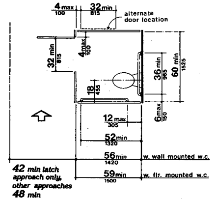
Figure 30(b) Alternate Stalls
(f) Assembly areas.
(i) In alterations where it is structurally impracticable to disperse seating throughout the assembly area, seating may be located in collected areas as structurally feasible. Seating shall adjoin an accessible route that also serves as a means of emergency egress.
(ii) In alterations where it is structurally impracticable to alter all performing areas to be on an accessible route, then at least one of each type shall be made accessible.
4.1.6(5) HOUSING.
(Reserved).
(a) As a general rule, the accessibility provisions of part 4 shall be applied to "qualified" historic buildings and facilities. "Qualified" buildings or facilities are those buildings and facilities that are eligible for listing in the National Register of Historic Places, or such properties designated as historic under a statute of the appropriate state or local government body. Comments of the Advisory Council on Historic Preservation shall be obtained when required by Section 106 of the National Historic Preservation Act of 1966, as amended, 16 U.S.C. 470 and 36 CFR Part 800, before any alteration to a qualified historic building.
(b) The Advisory Council shall determine, on a case-by-case basis, whether provisions required by part 4 for accessible routes (exterior and interior), ramps, entrances, toilets, parking, and displays and signage, would threaten or destroy the historic significance of the building or facility.
(c) If the Advisory Council determines that any of the accessibility requirements for features listed in 4.1.7(1) would threaten or destroy the historic significance of a building or facility, then the special application provisions of 4.1.7(2) for that feature may be utilized. The special application provisions listed under 4.1.7(2) may only be utilized following a written determination by the Advisory Council that application of a requirement contained in part 4 would threaten or destroy the historic integrity of a qualified building or facility.
(a) At least one accessible route complying with 4.3 from a site access point to an accessible entrance shall be provided.
EXCEPTION: A ramp with a slope no greater than 1:6 for a run not to exceed 2 ft (610 mm) may be used as part of an accessible route at an entrance.
(b) At least one accessible entrance which is used by the public complying with 4.14 shall be provided.
EXCEPTION: If it is determined that no entrance used by the public can comply with 4.14, then access at any entrance not used by the general public but open (unlocked) with directional signs at the primary entrance may be used.
(c) If toilets are provided, then at least one toilet facility complying with 4.22 and 4.1.6 shall be provided along an accessible route that complies with 4.3. Such toilet facility may be "unisex" in design.
(d) Accessible routes from an accessible entrance to all publicly used spaces on at least the level of the accessible entrance shall be provided. Access should be provided to all levels of a building or facility in compliance with 4.1 whenever practical.
(e) Displays and written information, documents, etc, should be located where they can be seen by a seated person. Exhibits and signage displayed horizontally, e.g., books, should be no higher than 44 in (1120 mm) above the floor surface.
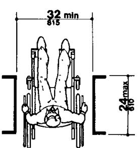
4.2.1* WHEELCHAIR PASSAGE WIDTH.
The minimum clear width for single wheelchair passage shall be 32 in (815 mm) at a point and 36 in (915 mm) continuously (see Fig. 1 and 24(e)).
Figure 1 Minimum Clear Width for Single Wheelchair
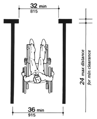
Figure 24(e) Maximum Doorway Depth

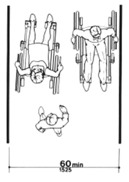
4.2.2 WIDTH FOR WHEELCHAIR PASSING.
The minimum width for two wheelchairs to pass is 60 in (1525 mm) (see Fig. 2).
Figure 2 Minimum Clear Width for Two Wheelchairs
4.2.3* WHEELCHAIR TURNING SPACE.
The space required for a wheelchair to make a 180-degree turn is a clear space of 60 in (1525 mm) diameter (see Fig. 3(a)) or a T-shaped space (see Fig. 3(b)).
Figure 3(a) 60-in (1525 mm) Diameter Space
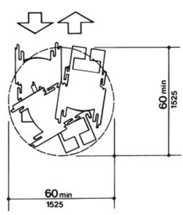
Figure 3(b) T-Shaped Space for 180 Degree Turns
4.2.4.1 SIZE AND APPROACH.
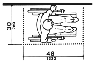
The minimum clear floor or ground space required to accommodate a single, stationary wheelchair occupant is 30 in by 48 in (760 mm by 1220 mm) (see Fig. 4(a)). The minimum clear floor or ground space for wheelchairs may be positioned for forward or parallel approach to an object (see Fig. 4(b) and (c)). Clear floor or ground space for wheelchairs may be part of the knee space required under some objects.
Figure 4
Minimum Clear Floor Space for Wheelchairs
Figure 4(a) Clear Floor Space
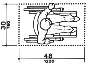
Figure 4(b) Forward Approach
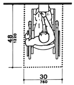
Figure 4(c) Parallel Approach
4.2.4.2 RELATIONSHIP OF MANEUVERING CLEARANCE TO WHEELCHAIR SPACES.
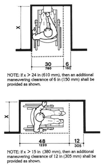
One full unobstructed side of the clear floor or ground space for a wheelchair shall adjoin or overlap an accessible route or adjoin another wheelchair clear floor space. If a clear floor space is located in an alcove or otherwise confined on all or part of three sides, additional maneuvering clearances shall be provided as shown in Fig. 4(d) and (e).
Figure 4 (cont.)
Minimum Clear Floor Space for Wheelchairs
Figure 4(d) Clear Floor Space in Alcoves
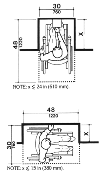
Figure 4(e) Additional Maneuvering Clearances for Alcoves
4.2.4.3 SURFACES FOR WHEELCHAIR SPACES.
Clear floor or ground spaces for wheelchairs shall comply with 4.5.
4.2.5 FORWARD REACH.
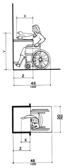
If the clear floor space only allows forward approach to an object, the maximum high forward reach allowed shall be 48 in (1220 mm) (see Fig. 5(a)). The minimum low forward reach is 15 in (380 mm). If the high forward reach is over an obstruction, reach and clearances shall be as shown in Fig. 5(b).
Figure 5
Forward Reach
Figure 5(a) High Forward Reach Limit
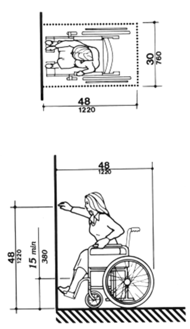
Figure 5(b) Maximum Forward Reach over an Obstruction
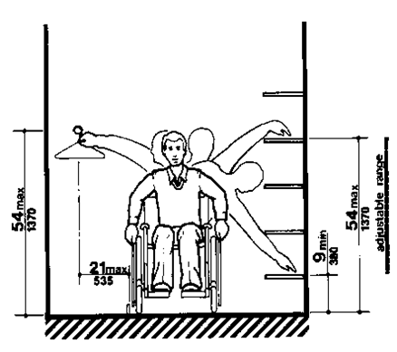
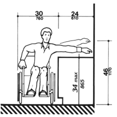
4.2.6* SIDE REACH.
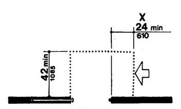
If the clear floor space allows parallel approach by a person in a wheelchair, the maximum high side reach allowed shall be 54 in (1370 mm) and the low side reach shall be no less than 9 in (230 mm) above the floor (Fig. 6(a) and (b)). If the side reach is over an obstruction, the reach and clearances shall be as shown in Fig. 6(c).
Figure 6
Side Reach
Figure 6(a) Clear Floor Space - Parallel Approach
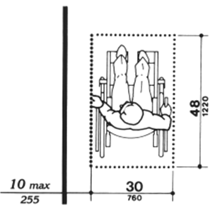
Figure 6(b) High and Low - Side Reach Limits
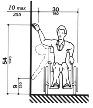
Figure 6(c) Maximum Side Reach over Obstruction
4.3.1* GENERAL.
All walks, halls, corridors, aisles, and other spaces that are part of an accessible route shall comply with 4.3.
4.3.2 LOCATION.
(1) At least one accessible route within the boundary of the site shall be provided from public transportation stops, accessible parking, and accessible passenger loading zones, and public streets or sidewalks to the accessible building entrance they serve.
(2) At least one accessible route shall connect accessible buildings, facilities, elements, and spaces that are on the same site.
(3) At least one accessible route shall connect accessible building or facility entrances with all accessible spaces and elements and with all accessible dwelling units within the building or facility.
(4) An accessible route shall connect at least one accessible entrance of each accessible dwelling unit with those exterior and interior spaces and facilities that serve the accessible dwelling unit.
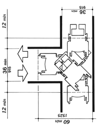
4.3.3 WIDTH.
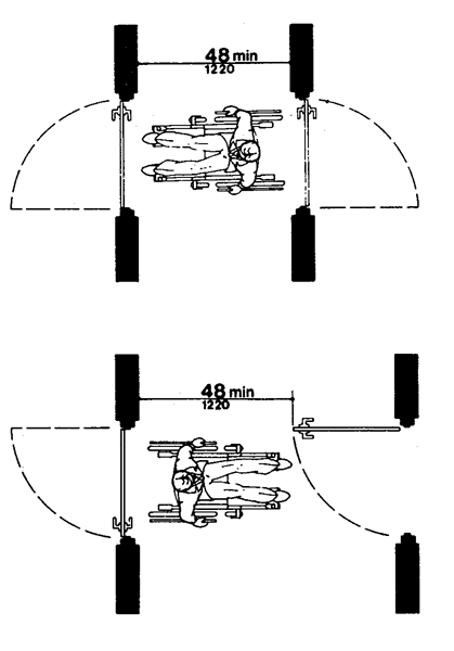
The minimum clear width of an accessible route shall be 36 in (915 mm) except at doors (see 4.13.5). If a person in a wheelchair must make a turn around an obstruction, the minimum clear width of the accessible route shall be as shown in Fig. 7.
Figure 7
Width of Accessible Route
Figure 7(a) 90 Degree Turn
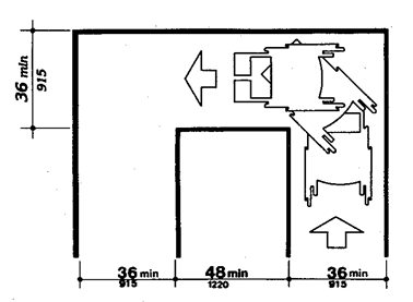
Note: Dimensions shown apply where x < 48 inches (1220 mm). Figure 7(b) Turn around an Obstruction
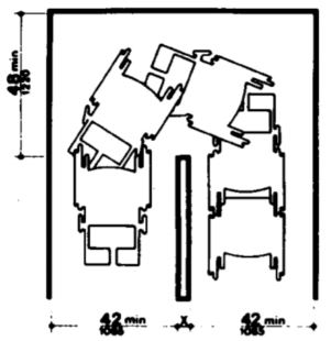
Figure 7(c) Changes in Level
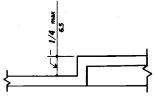
Figure 7(d) Changes in Level
4.3.4 PASSING SPACE.
If an accessible route has less than 60 in (1525 mm) clear width, then passing spaces at least 60 in by 60 in (1525 mm by 1525 mm) shall be located at reasonable intervals not to exceed 200 ft (61 m). A T-intersection of two corridors or walks is an acceptable passing place.
4.3.5 HEAD ROOM.
Accessible routes shall comply with 4.4.2.
4.3.6 SURFACE TEXTURES.
The surface of an accessible route shall comply with 4.5.
4.3.7 SLOPE.
An accessible route with a running slope greater than 1:20 is a ramp and shall comply with 4.8. Nowhere shall the cross slope of an accessible route exceed 1:50.
4.3.8 CHANGES IN LEVELS.
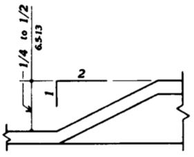
Changes in levels along an accessible route shall comply with 4.5.2. If an accessible route has changes in level greater than 1/2 in (13 mm), then a curb ramp, ramp, elevator, or platform lift shall be provided that complies with 4.7, 4.8, 4.10, or 4.11, respectively. Stairs shall not be part of an accessible route.
4.3.9 DOORS.
Doors along an accessible route shall comply with 4.13.
4.3.10* EGRESS.
Accessible routes serving any accessible space or element shall also serve as a means of egress for emergencies or connect to an accessible place of refuge. Such accessible routes and places of refuge shall comply with the requirements of the administrative authority having jurisdiction. Where fire code provisions require more than one means of egress from any space or room, then more than one accessible means of egress shall also be provided for handicapped people. Arrange egress so as to be readily accessible from all accessible rooms and spaces.
4.4.1* GENERAL.
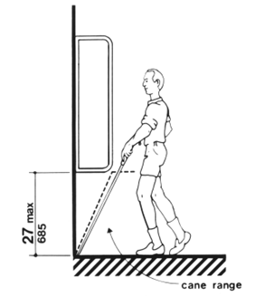
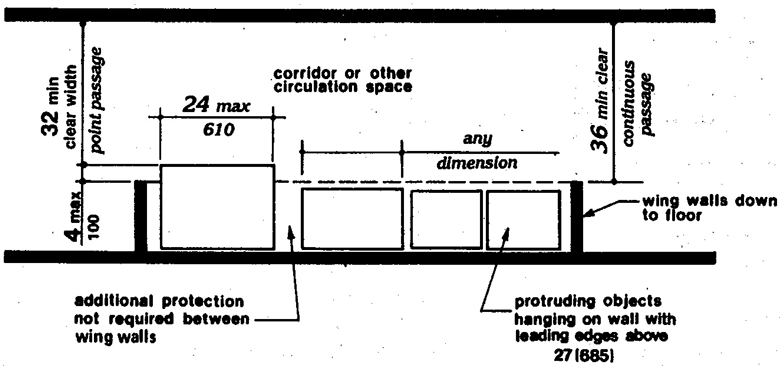
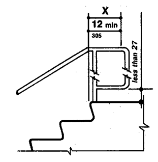
Objects projecting from walls (for example, telephones) with their leading edges between 27 in and 80 in (685 mm and 2030 mm) above the finished floor shall protrude no more than 4 in (100 mm) into walks, halls, corridors, passageways, or aisles (see Fig. 8(a)). Objects mounted with their leading edges at or below 27 in (685 mm) above the finished floor may protrude any amount (see Fig. 8(a) and (b)). Free-standing objects mounted on posts or pylons may overhang 12 in (305 mm) maximum from 27 in to 80 in (685 mm to 2030 mm) above the ground or finished floor (see Fig. 8(c) and (d)). Protruding objects shall not reduce the clear width of an accessible route or maneuvering space (see Fig. 8(e)).
Figure 8 Protruding Objects
Figure 8(a) Walking Parallel to a Wall
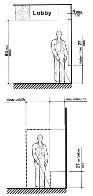
Figure 8(b) Walking Perpendicular to a Wall
Freestanding Overhanging Objects
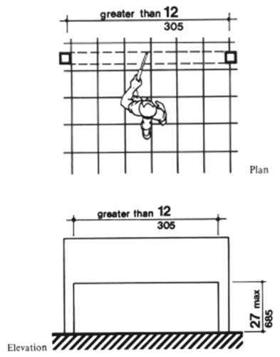
Figure 8(c) (cont.) Overhead Hazards

Figure 8(d) Objects Mounted on Posts or Pylons
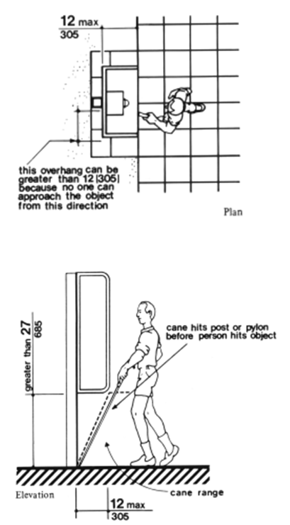
Figure 8(e) Example of Protection around Wall-mounted Objects and Measurements of Clear Widths
4.4.2 HEAD ROOM.
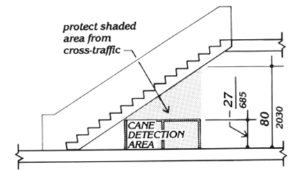
Walks, halls, corridors, passageways, aisles, or other circulation spaces shall have 80 in (2030 mm) minimum clear head room (see Fig. 8(a)). If vertical clearance of an area adjoining an accessible route is reduced to less than 80 in (nominal dimension), a barrier to warn blind or visually-impaired persons shall be provided (see Fig. 8(c)).
Figure 8(a) Walking Parallel to a Wall

Figure 8(c) (cont.) Overhead Hazards
4.5.1* GENERAL.
Ground and floor surfaces along accessible routes and in accessible rooms and spaces, including floors, walks, ramps, stairs, and curb ramps, shall be stable, firm, slip-resistant, and shall comply with 4.5.
4.5.2 CHANGES IN LEVEL.
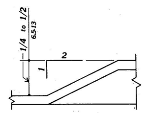
Changes in level up to 1/4 in (6 mm) may be vertical and without edge treatment (see Fig. 7(c)). Changes in level between 1/4 in and 1/2 in (6 mm and 13 mm) shall be beveled with a slope no greater than 1:2 (see Fig. 7(d)). Changes in level greater than 1/2 in (13 mm) shall be accomplished by means of a ramp that complies with 4.7 or 4.8.
Figure 7(c) Changes in Level
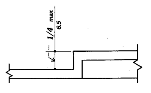
Figure 7(d) Changes in Level
4.5.3* CARPET.
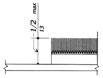
If carpet or carpet tile is used on a ground or floor surface, then it shall be securely attached; have a firm cushion, pad, or backing or no cushion or pad; and have a level loop, textured loop, level cut pile, or level cut/uncut pile texture. The maximum pile height shall be 1/2 in (13 mm). Exposed edges of carpet shall be fastened to floor surfaces and have trim along the entire length of the exposed edge. Carpet edge trim shall comply with 4.5.2. If carpet tile is used on an accessible ground or floor surface, it shall have a maximum combined thickness of pile, cushion, and backing height of 1/2 in (13 mm) (see Fig. 8(f)).
Figure 8(f) Carpet Tile Thickness
4.5.4 GRATINGS.
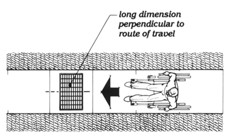
If gratings are located in walking surfaces, then they shall have spaces no greater than 1/2 in (13 mm) wide in one direction (see Fig. 8(g)). If gratings have elongated openings, then they shall be placed so that the long dimension is perpendicular to the dominant direction of travel (see Fig. 8(h)).
Figure 8(g) Gratings
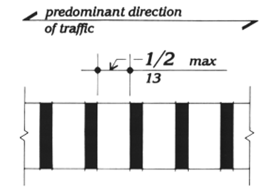
Figure 8(h) Grating Orientation
4.6.1 MINIMUM NUMBER.
Parking spaces required to be accessible by 4.1 shall comply with 4.6.2 through 4.6.4. Passenger loading zones required to be accessible by 4.1 shall comply with 4.6.5 and 4.6.6.
4.6.2 LOCATION.
Parking spaces for disabled people and accessible passenger loading zones that serve a particular building shall be the spaces or zones located closest to the nearest accessible entrance on an accessible route. In separate parking structures or lots that do not serve a particular building, parking spaces for disabled people shall be located on the shortest possible circulation route to an accessible pedestrian entrance of the parking facility.
4.6.3* PARKING SPACES.
Parking spaces for disabled people shall be at least 96 in (2440 mm) wide and shall have an adjacent access aisle 60 in (1525 mm) wide minimum (see Fig. 9). Parking access aisles shall be part of an accessible route to the building or facility entrance and shall comply with 4.3. Two accessible parking spaces may share a common access aisle. Parked vehicle overhangs shall not reduce the clear width of an accessible circulation route. Parking spaces and access aisles shall be level with surface slopes not exceeding 1:50 in all directions.
Figure 9 Dimensions of Parking Spaces
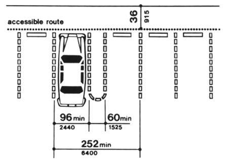
EXCEPTION: If accessible parking spaces for vans designed for handicapped persons are provided, each should have an adjacent access aisle at least 96 in (2440 mm) wide complying with 4.5, Ground and Floor Surfaces.
4.6.4* SIGNAGE.
Accessible parking spaces shall be designated as reserved for the disabled by a sign showing the symbol of accessibility (see 4.30.5). Such signs shall not be obscured by a vehicle parked in the space.
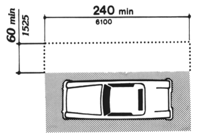
4.6.5 PASSENGER LOADING ZONES.
Passenger loading zones shall provide an access aisle at least 60 in (1525 mm) wide and 20 ft (6 m) long adjacent and parallel to the vehicle pull-up space (see Fig. 10). If there are curbs between the access aisle and the vehicle pull-up space, then a curb ramp complying with 4.7 shall be provided. Vehicle standing spaces and access aisles shall be level with surface slopes not exceeding 1:50 in all directions.
Figure 10 Access Aisle at Passenger Loading Zones
4.6.6 VERTICAL CLEARANCE.
Provide minimum vertical clearances of 114 in at accessible passenger loading zones and along vehicle access routes to such areas from site entrances. If accessible van parking spaces are provided, then the minimum vertical clearance should be 114 in.
4.7.1 LOCATION.
Curb ramps complying with 4.7 shall be provided wherever an accessible route crosses a curb.
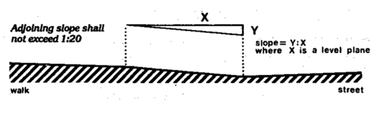
4.7.2 SLOPE.
Slopes of curb ramps shall comply with 4.8.2. The slope shall be measured as shown in Fig. 11. Transitions from ramps to walks, gutters, or streets shall be flush and free of abrupt changes. Maximum slopes of adjoining gutters, road surface immediately adjacent to the curb ramp, or accessible route shall not exceed 1.20.
Figure 11 Measurement of Curb Ramp Slopes
4.7.3 WIDTH.
The minimum width of a curb ramp shall be 36 in (915 mm), exclusive of flared sides.
4.7.4 SURFACE.
Surfaces of curb ramps shall comply with 4.5.
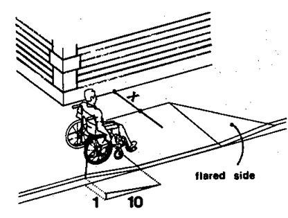
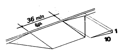
4.7.5 SIDES OF CURB RAMPS.
If a curb ramp is located where pedestrians must walk across the ramp, or where it is not protected by handrails or guardrails, then it shall have flared sides; the maximum slope of the flare shall be 1:10 (see Fig. 12(a)). Curb ramps with returned curbs may be used where pedestrians would not normally walk across the ramp (see Fig. 12(b)).
Figure 12 Sides of Curb Ramps
If X is less than 48 inches, then the slope of the flared side shall not exceed 1:12. Figure 12(a) Flared Sides
If X is less than 48 inches, then the slope of the flared side shall not exceed 1:12. Figure 12(b) Returned Curb
4.7.6 BUILT-UP CURB RAMPS.
Built-up curb ramps shall be located so that they do not project into vehicular traffic lanes (see Fig. 13).
Figure 13 Built-up Curb Ramp (Figure 14 not used.)
4.7.7 WARNING TEXTURES.
(Removed and reserved).
4.7.8 OBSTRUCTIONS.
Curb ramps shall be located or protected to prevent their obstruction by parked vehicles.
4.7.9 LOCATION AT MARKED CROSSINGS.
Curb ramps at marked crossings shall be wholly contained within the markings, excluding any flared sides (see Fig. 15).
Figure 15
Curb Ramps at Marked Crossings
Figure 15(a)

Figure 15(b)

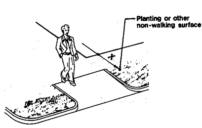
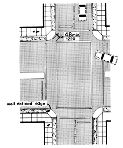
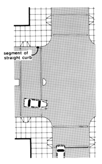
4.7.10 DIAGONAL CURB RAMPS.
If diagonal (or corner type) curb ramps have returned curbs or other well-defined edges, such edges shall be parallel to the direction of pedestrian flow. The bottom of diagonal curb ramps shall have 48 in (1220 mm) minimum clear space as shown in Fig. 15(c) and (d). If diagonal curb ramps are provided at marked crossings, the 48 in (1220 mm) clear space shall be within the markings (see Fig. 15(c) and (d)). If diagonal curb ramps have flared sides, they shall also have at least a 24 in (610 mm) long segment of straight curb located on each side of the curb ramp and within the marked crossing (see Fig. 15(c)).
Figure 15(c)
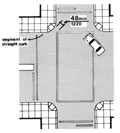
Figure 15(d)
4.7.11 ISLANDS.
Any raised islands in crossings shall be cut through level with the street or have curb ramps at both sides and a level area at least 48 in (1220 mm) long in the part of the island intersected by the crossings (see Fig. 15(a) and (b)).
Figure 15(a)
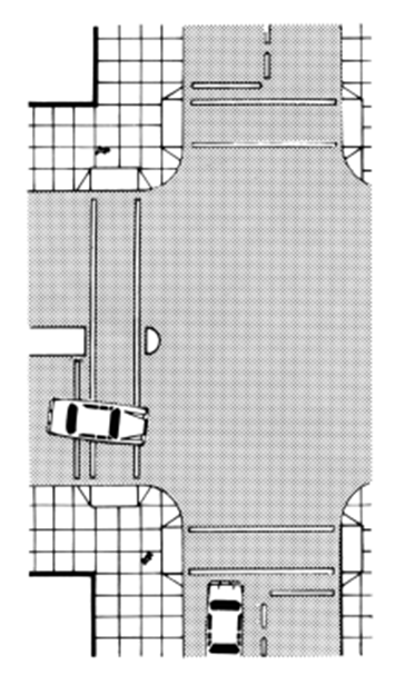
Figure 15(b)
4.7.12 UNCURBED INTERSECTIONS.
(Removed and reserved).
4.8.1* GENERAL.
Any part of an accessible route with a slope greater than 1:20 shall be considered a ramp and shall comply with 4.8.
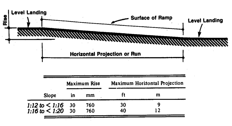
4.8.2* SLOPE AND RISE.
The least possible slope shall be used for any ramp. The maximum slope of a ramp in new construction shall be 1:12. The maximum rise for any run shall be 30 in (760 mm) (see Fig. 16). Curb ramps and ramps to be constructed on existing sites or in existing buildings or facilities may have slopes and rises as shown in Table 2 if space limitations prohibit the use of a 1:12 slope or less (see 4.1.6).
Figure 16 Components of a Single Ramp Run and Sample Ramp Dimensions
4.8.3 CLEAR WIDTH.
The minimum clear width of a ramp shall be 36 in (915 mm).
4.8.4 LANDINGS.
Ramps shall have level landings at the bottom and top of each run. Landings shall have the following features:
(1) The landing shall be at least as wide as the ramp run leading to it.
(2) The landing length shall be a minimum of 60 in (1525 mm) clear.
(3) If ramps change direction at landings, the minimum landing size shall be 60 in by 60 in (1525 mm by 1525 mm).
(4) If a doorway is located at a landing, then the area in front of the doorway shall comply with 4.13.6.
4.8.5* HANDRAILS.
If a ramp run has a rise greater than 6 in (250 mm) or a horizontal projection greater than 72 in (1830 mm), then it shall have handrails on both sides. Handrails are not required on curb ramps. Handrails shall comply with 4.26 and shall have the following features:
(1) Handrails shall be provided along both sides of ramp segments. The inside handrail on switchback or dogleg ramps shall always be continuous.
(2) If handrails are not continuous, they shall extend at least 12 in (305 mm) beyond the top and bottom of the ramp segment and shall be parallel with the floor or ground surface.
(3) The clear space between the handrail and the wall shall be 1-1/2 in (38 mm).
(4) Gripping surfaces shall be continuous.
(5) Top of handrail gripping surfaces shall be mounted between 30 in and 34 in (760 mm and 865 mm) above ramp surfaces.
(6) Ends of handrails shall be either rounded or returned smoothly to floor, wall or post.
(7) Handrails shall not rotate within their fittings.
4.8.6 CROSS SLOPE AND SURFACES.
The cross slope of ramp surfaces shall be no greater than 1:50. Ramp surfaces shall comply with 4.5.
4.8.7 EDGE PROTECTION.
Ramps and landings with drop-offs shall have curbs, walls, railings, or projecting surfaces that prevent people from slipping off the ramp. Curbs shall be a minimum of 2 in (50 mm) high (see Fig. 17).
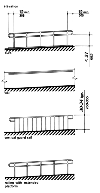
Figure 17 Examples of Edge Protection And Handrail Extensions
4.8.8 OUTDOOR CONDITIONS.
Outdoor ramps and their approaches shall be designed so that water will not accumulate on walking surfaces.
4.9.1 MINIMUM NUMBER.
Stairs required to be accessible by 4.1 shall comply with 4.9.
4.9.2 TREADS AND RISERS.
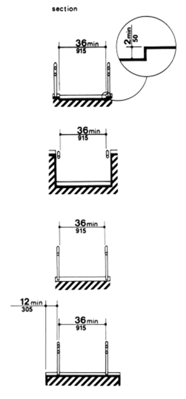
On any given flight of stairs, all steps shall have uniform riser heights and uniform tread widths. Stair treads shall be no less than 11 in (280 mm) wide, measured from riser to riser (see Fig. 18(a)). Open risers are not permitted on accessible routes.
Figure 18 Usable Tread Width and Examples of Acceptable Nosings
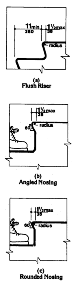
4.9.3 NOSINGS.
The undersides of nosings shall not be abrupt. The radius of curvature at the leading edge of the tread shall be no greater than 1/2 in (13 mm). Risers shall be sloped or the underside of the nosing shall have an angle not less than 60 degrees from the horizontal. Nosings shall project no more than 1-1/2 in (38 mm) (see Fig. 18).
4.9.4 HANDRAILS.
Stairways shall have handrails at both sides of all stairs. Handrails shall comply with 4.26 and shall have the following features:
(1) Handrails shall be continuous along both sides of stairs. The inside handrail on switchback or dogleg stairs shall always be continuous (see Fig. 19(a) and (b)).
Figure 19
Stair Handrails
Figure 19(a) Plan Note: X is the 12 in minimum handrail extension required at each top riser. Y is the minimum handrail extension of 12 in plus the width of one tread that is required at each bottom riser.
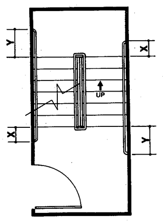
Figure 19(b) Elevation of Center Handrail
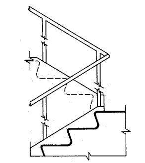
(2) If handrails are not continuous, they shall extend at least 12 in (305 mm) beyond the top riser and at least 12 in (305 mm) plus the width of one tread beyond the bottom riser. At the top, the extension shall be parallel with the floor or ground surface. At the bottom, the handrail shall continue to slope for a distance of the width of one tread from the bottom riser; the remainder of the extension shall be horizontal (see Fig. 19(c) and (d)). Handrail extensions shall comply with 4.4.
Figure 19(c) Extension at Bottom of Run Note: Y is the minimum handrail extension of 12 in plus the width of one tread that is required at each bottom riser.
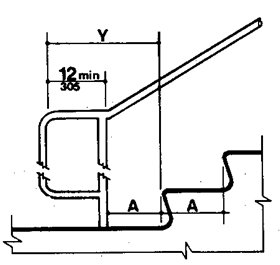
Figure 19(d) Extension at Top of Run Note: X is the 12 in minimum handrail extension required at each top riser.
(3) The clear space between handrails and wall shall be 1-1/2 in (38 mm).
(4) Gripping surfaces shall be uninterrupted by newel posts, other construction elements, or obstructions.
(5) Top of handrail gripping surface shall be mounted between 30 in and 34 in (760 mm and 865 mm) above stair nosings.
(6) Ends of handrails shall be either rounded or returned smoothly to floor, wall, or post.
(7) Handrails shall not rotate within their fittings.
4.9.5 TACTILE WARNINGS AT STAIRS.
(Removed and reserved).
4.9.6 OUTDOOR CONDITIONS.
Outdoor stairs and their approaches shall be designed so that water will not accumulate on walking surfaces.
4.10.1 GENERAL.
Accessible elevators shall be on an accessible route and shall comply with 4.10 and with the American National Standard Safety Code for Elevators, Dumbwaiters, Escalators, and Moving Walks, ANSI A17.1-1978 and A17.1a-1979. This standard does not preclude the use of residential or fully enclosed wheelchair lifts when appropriate and approved by administrative authorities. Freight elevators shall not be considered as meeting the requirements of this section, unless the only elevators provided are used as combination passenger and freight elevators for the public and employees.
4.10.2 AUTOMATIC OPERATION.
Elevator operation shall be automatic. Each car shall be equipped with a self-leveling feature that will automatically bring the car to floor landings within a tolerance of 1/2 in (13 mm) under rated loading to zero loading conditions. This self-leveling feature shall be automatic and independent of the operating device and shall correct the over-travel or undertravel.
4.10.3 HALL CALL BUTTONS.
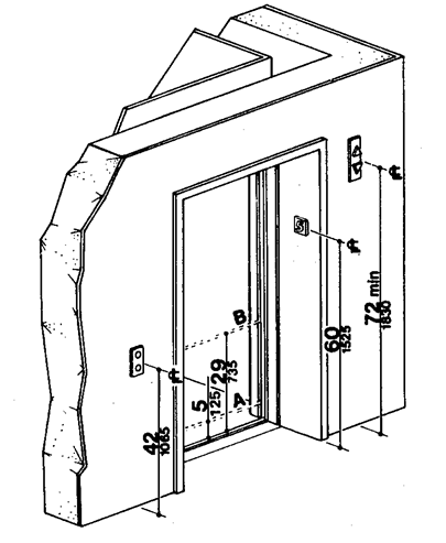
Call buttons in elevator lobbies and halls shall be centered at 42 in (1065 mm) above the floor. Such call buttons shall have visual signals to indicate when each call is registered and when each call is answered. Call buttons shall be a minimum of 3/4 in (19 mm) in the smallest dimension. The button designating the up direction shall be on top (see Fig. 20). Buttons shall be raised or flush. Objects mounted beneath hall call buttons shall not project into the elevator lobby more than 4 in (100 mm).
Figure 20 Hoistway and Elevator Entrances Note: The automatic reopening device is activated if an object passes through either line A or line B. Line A and line B represent the vertical locations of the door reopening device not requiring contact.
4.10.4 HALL LANTERNS.
A visible and audible signal shall be provided at each hoistway entrance to indicate which car is answering a call. Audible signals shall sound once for the up direction and twice for the down direction or shall have verbal annunciators that say "up" or "down." Visible signals shall have the following features:
(1) Hall lantern fixtures shall be mounted so that their centerline is at least 72 in (1830 mm) above the lobby floor.
(2) Visual elements shall be at least 2-1/2 in (64 mm) in the smallest dimension.
(3) Signals shall be visible from the vicinity of the hall call button. In-car lanterns located in cars, visible from the vicinity of hall call buttons, and conforming to the above requirements, shall be acceptable (see Fig. 20).
4.10.5 RAISED CHARACTERS ON HOISTWAY ENTRANCES.
All elevator hoistway entrances shall have raised floor designations provided on both jambs. The centerline of the characters shall be 60 in (1525 mm) from the floor. Such characters shall be 2 in (50 mm) high and shall comply with 4.30. Permanently applied plates are acceptable if they are permanently fixed to the jambs. (See Fig. 20).
4.10.6* DOOR PROTECTIVE AND REOPENING DEVICE.
Elevator doors shall open and close automatically. They shall be provided with a reopening device that will stop and reopen a car door and hoistway door automatically if the door becomes obstructed by an object or person. The device shall be capable of completing these operations without requiring contact for an obstruction passing through the opening at heights of 5 in and 29 in (125 mm and 735 mm) from the floor (see Fig. 20). Door reopening devices shall remain effective for at least 20 seconds. After such an interval, doors may close in accordance with the requirements of ANSI A17.1-1978 and A17.1a-1979.
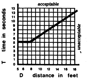
4.10.7* DOOR AND SIGNAL TIMING FOR HALL CALLS.
The minimum acceptable time from notification that a car is answering a call until the doors of that car start to close shall be calculated from the following equation:
T = D or T = D
1.5 ft/s 445 mm/s
where T = total time in seconds and D = distance (in feet or millimeters) from a point in the lobby or corridor 60 in (1525 mm) directly in front of the farthest call button controlling that car to the centerline of its hoistway door (see Fig. 21). For cars with in-car lanterns, T begins when the lantern is visible from the vicinity of hall call buttons and an audible signal is sounded. The minimum acceptable notification time shall be 5 seconds.
Figure 21 Graph of Timing Equation
4.10.8 DOOR DELAY FOR CAR CALLS.
The minimum time for elevator doors to remain fully open in response to a car call shall be 3 seconds.
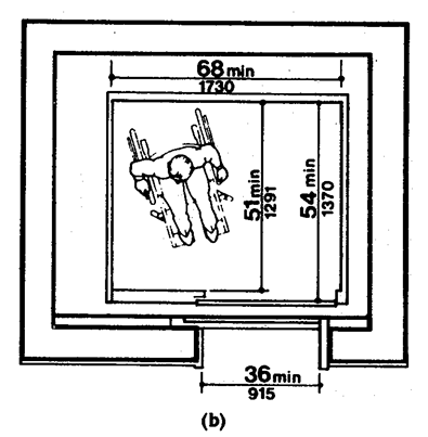
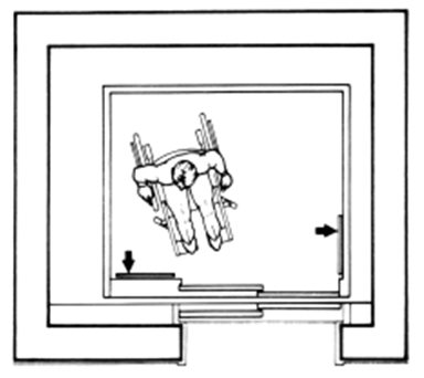
4.10.9 FLOOR PLAN OF ELEVATOR CARS.
The floor area of elevator cars shall provide space for wheelchair users to enter the car, maneuver within reach of controls, and exit from the car. Acceptable door opening and inside dimensions shall be as shown in Fig. 22. The clearance between the car platform sill and the edge of any hoistway landing shall be no greater than 1-1/4 in (32 mm).
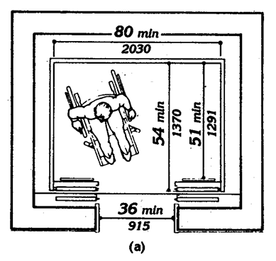
Figure 22 Minimum Dimensions of Elevator Cars
4.10.10 FLOOR SURFACES.
Floor surfaces shall comply with 4.5.
4.10.11 ILLUMINATION LEVELS.
The level of illumination at the car controls, platform, and car threshold and landing sill shall be at least 5 footcandles (53.8 lux).
4.10.12* CAR CONTROLS.
Elevator control panels shall have the following features:
(1) Buttons. All control buttons shall be at least 3/4 in (19 mm) in their smallest dimension. They may be raised or flush.
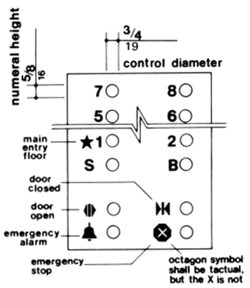
(2) Tactile and Visual Control Indicators. All control buttons shall be designated by raised standard alphabet characters for letters, arabic characters for numerals, or standard symbols as shown in Fig. 23(a), and as required in ANSI A17.1-1978 and A17.1a-1979. Raised characters and symbols shall comply with 4.30. The call button for the main entry floor shall be designated by a raised star at the left of the floor designation (see Fig. 23(a)). All raised designations for control buttons shall be placed immediately to the left of the button to which they apply. Applied plates, permanently attached, are an acceptable means to provide raised control designations. Floor buttons shall be provided with visual indicators to show when each call is registered. The visual indicators shall be extinguished when each call is answered.
Figure 23
Car Controls
Figure 23(a) Panel Detail
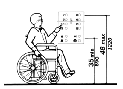
(3) Height. All floor buttons shall be no higher than 48 in (1220 mm), unless there is a substantial increase in cost, in which case the maximum mounting height may be increased to 54 in (1370 mm), above the floor. Emergency controls, including the emergency alarm and emergency stop, shall be grouped at the bottom of the panel and shall have their centerlines no less than 35 in (890 mm) above the floor (see Fig. 23(a) and (b)).
Figure 23(b) Car Control Height
(4) Location. Controls shall be located on a front wall if cars have center opening doors, and at the side wall or at the front wall next to the door if cars have side opening doors (see Fig. 23(c) and (d)).
Figure 23(c) Alternate Locations of Panel with Center Opening Door
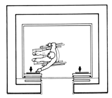
Figure 23(d) Alternate Locations of Panel with Side Opening Door
4.10.13* CAR POSITION INDICATORS.
In elevator cars, a visual car position indicator shall be provided above the car control panel or over the door to show the position of the elevator in the hoistway. As the car passes or stops at a floor served by the elevators, the corresponding numerals shall illuminate, and an audible signal shall sound. Numerals shall be a minimum of 1/2 in (13 mm) high. The audible signal shall be no less than 20 decibels with a frequency no higher than 1500 Hz. An automatic verbal announcement of the floor number at which a car stops or which a car passes may be substituted for the audible signal.
4.10.14* EMERGENCY COMMUNICATIONS.
If provided, emergency two-way communication systems between the elevator and a point outside the hoistway shall comply with ANSI A17.1-1978 and A17.1a-1979. The highest operable part of a two-way communication system shall be a maximum of 48 in (1220 mm) from the floor of the car. It shall be identified by a raised or recessed symbol and lettering complying with 4.30 and located adjacent to the device. If the system uses a handset, then the length of the cord from the panel to the handset shall be at least 29 in (735 mm). If the system is located in a closed compartment, the compartment door hardware shall conform to 4.27, Controls and Operating Mechanisms. The emergency intercommunication system shall not require voice communication.
4.11.1 LOCATION.
Platform lifts permitted by 4.1 shall comply with the requirements of 4.11.
4.11.2 OTHER REQUIREMENTS.
If platform lifts are used, they shall comply with 4.2.4, 4.5, 4.27, and the applicable safety regulations of administrative authorities having jurisdiction.
4.11.3 ENTRANCE.
If platform lifts are used, then they should facilitate unassisted entry and exit from the lift in compliance with 4.11.2.
4.12 WINDOWS. (Reserved).
4.13.1 GENERAL.
Doors required to be accessible by 4.1 shall comply with the requirements of 4.13.
4.13.2 REVOLVING DOORS AND TURNSTILES.
Revolving doors or turnstiles shall not be the only means of passage at an accessible entrance or along an accessible route. An accessible gate or door shall be provided adjacent to the turnstile or revolving door and shall be so designed as to facilitate the same use pattern.
4.13.3 GATES.
Gates, including ticket gates, shall meet all applicable specifications of 4.13.
4.13.4 DOUBLE-LEAF DOORWAYS.
If doorways have two independently operated door leaves, then at least one leaf shall meet the specifications in 4.13.5 and 4.13.6. That leaf shall be an active leaf.
4.13.5 CLEAR WIDTH.
Doorways shall have a minimum clear opening of 32 in (815 mm) with the door open 90 degrees, measured between the face of the door and the stop (see Fig. 24(a), (b), (c), and (d)). Openings more than 24 in (610 mm) in depth shall comply with 4.2.1 and 4.3.3 (see Fig. 24(e)).
EXCEPTION: Doors not requiring full user passage, such as shallow closets, may have the clear opening reduced to 20 in (510 mm) minimum.
Figure 24
Clear Doorway Width and Depth
Figure 24(a) Detail
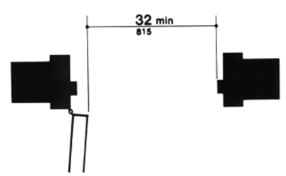
Figure 24(b) Hinged Door
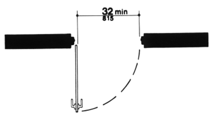
Figure 24(c) Sliding Door

Figure 24(d) Folding Door

Figure 24(e) Maximum Doorway Depth
4.13.6 MANEUVERING CLEARANCES AT DOORS.
Minimum maneuvering clearances at doors that are not automatic or power-assisted shall be as shown in Fig. 25. The floor or ground area within the required clearances shall be level and clear. Entry doors to acute care hospital bedrooms for in-patients shall be exempted from the requirement for space at the latch side of the door (see dimension "x" in Fig. 25) if the door is at least 44 in (1120 mm) wide.
Figure 25
Maneuvering Clearances at Doors
Figure 25(a) Front Approaches Swinging Doors
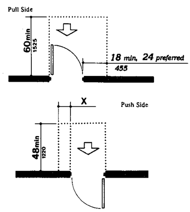
Figure 25(b) Hinge Side Approaches—Swinging Doors
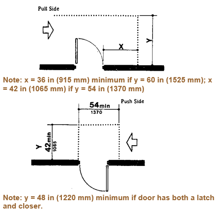
Figure 25(c) Latch Side Approaches—Swinging Doors
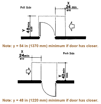
Figure 25(d) Front Approach—Sliding Doors and Folding Doors
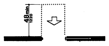
Figure 25(e) Slide Side Approach—Sliding Doors and Folding Doors
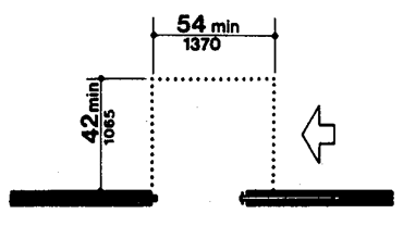
Figure 25(f) Latch Side Approach—Sliding Doors and Folding Doors
4.13.7 TWO DOORS IN SERIES.
The minimum space between two hinged or pivoted doors in series shall be 48 in (1220 mm) plus the width of any door swinging into the space. Doors in series shall swing either in the same direction or away from the space between the doors (see Fig. 26).
Figure 26 Two Hinged doors in Series
4.13.8* THRESHOLDS AT DOORWAYS.
Thresholds at doorways shall not exceed 3/4 in (19 mm) in height for exterior sliding doors or 1/2 in (13 mm) for other types of doors. Raised thresholds and floor level changes at accessible doorways shall be beveled with a slope no greater than 1:2 (see 4.5.2).
4.13.9* DOOR HARDWARE.
Handles, pulls, latches, locks, and other operating devices on accessible doors shall have a shape that is easy to grasp with one hand and does not require tight grasping, tight pinching, or twisting of the wrist to operate. Lever-operated mechanisms, push-type mechanisms, and U-shaped handles are acceptable designs. When sliding doors are fully open, operating hardware shall be exposed and usable from both sides. In dwelling units, only doors at accessible entrances to the unit itself shall comply with the requirements of this paragraph. Doors to hazardous areas shall have hardware complying with 4.29.3. Mount no hardware required for accessible door passage higher than 48 in (1220 mm) above finished floor.
4.13.10* DOOR CLOSERS.
If a door has a closer, then the sweep period of the closer shall be adjusted so that from an open position of 70 degrees, the door will take at least 3 seconds to move to a point 3 in (75 mm) from the latch, measured to the leading edge of the door.
4.13.11* DOOR OPENING FORCE.
The maximum force for pushing or pulling open a door shall be as follows:
(1) Fire doors shall have the minimum opening force allowable by the appropriate administrative authority.
(2) Other doors.
(a) exterior hinged doors: (Reserved).
(b) interior hinged doors: 5 lbf (22.2N)
(c) sliding or folding doors: 5 lbf (22.2N)
These forces do not apply to the force required to retract latch bolts or disengage other devices that may hold the door in a closed position.
4.13.12* AUTOMATIC DOORS AND POWER-ASSISTED DOORS.
If an automatic door is used, then it shall comply with American National Standard for Power-Operated Doors, ANSI A156.10-1979. Slowly opening, low-powered, automatic doors shall be considered a type of custom design installation as described in paragraph 1.1.1 of ANSI A156.10-1979. Such doors shall not open to back check faster than 3 seconds and shall require no more than 15 lbf (66.6N) to stop door movement. If a power-assisted door is used, its door-opening force shall comply with 4.13.11 and its closing shall conform to the requirements in section 10 of ANSI A156.10-1979.
4.14.1 MINIMUM NUMBER.
Entrances required to be accessible by 4.1 shall be part of an accessible route and shall comply with 4.3. Such entrances shall be connected by an accessible route to public transportation stops, to accessible parking and passenger loading zones, and to public streets or sidewalks if available (see 4.3.2(1)). They shall also be connected by an accessible route to all accessible spaces or elements within the building or facility.
4.14.2 SERVICE ENTRANCES.
A service entrance shall not be the sole accessible entrance unless it is the only entrance to a building or facility (for example, in a factory or garage).
4.15.1 MINIMUM NUMBER.
Drinking fountains or water coolers required to be accessible by 4.1 shall comply with 4.15.
4.15.2* SPOUT HEIGHT.
Spouts shall be no higher than 36 in (915 mm), measured from the floor or ground surfaces to the spout outlet (see Fig. 27(a)).
Figure 27
Drinking Fountains and Water Coolers
Note: equipment permitted in shaded area. Figure 27(a) Spout Height and Knee Clearance
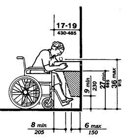
Figure 27(b) Clear Floor Space
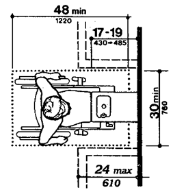
Figure 27(c) Free-standing Fountain or Cooler
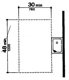
Figure 27(d) Built-in Fountain or Cooler
4.15.3 SPOUT LOCATION.
The spouts of drinking fountains and water coolers shall be at the front of the unit and shall direct the water flow in a trajectory that is parallel or nearly parallel to the front of the unit. The spout shall provide a flow of water at least 4 in (100 mm) high so as to allow the insertion of a cup or glass under the flow of water.
4.15.4 CONTROLS.
Controls shall comply with 4.27.4. Unit controls shall be front mounted or side mounted near the front edge.
(1) Wall- and post-mounted cantilevered units shall have a clear knee space between the bottom of the apron and the floor or ground at least 27 in (685 mm) high, 30 in (760 mm) wide, and 17 in to 19 in (430 mm to 485 mm) deep (see Fig. 27(a) and (b)). Such units shall also have a minimum clear floor space 30 in by 48 in (760 mm by 1220 mm) to allow a person in a wheelchair to approach the unit facing forward.
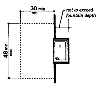
(2) Free standing or built-in units not having a clear space under them shall have a clear floor space at least 30 in by 48 in (760 mm by 1220 mm) that allows a person in a wheelchair to make a parallel approach to the unit (see Fig. 27(c) and (d)). This clear floor space shall comply with 4.2.4.
4.16.1 GENERAL.
Accessible water closets shall comply with 4.16. For water closets in accessible dwelling units, see 4.34.5.2.
4.16.2 CLEAR FLOOR SPACE.
Clear floor space for water closets not in stalls shall comply with Fig. 28. Clear floor space may be arranged to allow either a left-handed or right-handed approach.
Figure 28
Clear Floor Space at Water Closets
Possible wall locations ------
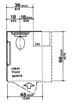
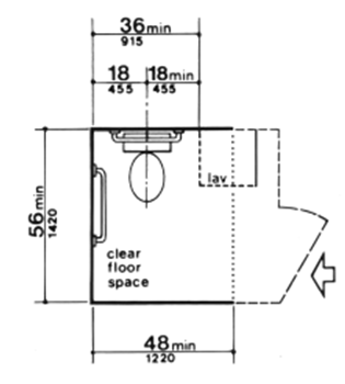
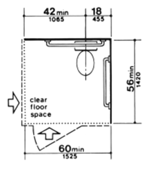
Figure 29
Grab Bars at Water Closets
Figure 29(a) Back Wall
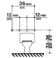
Figure 29(b) Side Wall
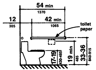
4.16.3* HEIGHT.
The height of water closets shall be 17 in to 19 in (430 mm to 485 mm), measured to the top of the toilet seat (see Fig. 29(b)). Seats shall not be sprung to return to a lifted position.
4.16.4* GRAB BARS.
Grab bars for water closets not located in stalls shall comply with Fig. 29 and 4.26.
4.16.5* FLUSH CONTROLS.
Flush controls shall be hand operated or automatic and shall comply with 4.27.4. Controls for flush valves shall be mounted on the wide side of toilet areas no more than 44 in (1120 mm) above the floor.
4.16.6 DISPENSERS.
Toilet paper dispensers shall be installed within reach, as shown in Fig. 29(b). Dispensers that control delivery, or that do not permit continuous paper flow, shall not be used.
4.17.1 LOCATION.
Accessible toilet stalls shall be on an accessible route and shall meet the requirements of 4.17.
4.17.2 WATER CLOSETS.
Water closets in accessible stalls shall comply with 4.16.
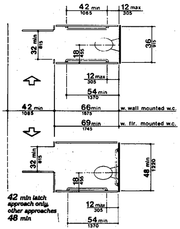
4.17.3 SIZE AND ARRANGEMENT.
The size and arrangement of toilet stalls shall comply with Fig. 30(a). Toilet stalls with a minimum depth of 56 in (1420 mm) (see Fig. 30(a)) shall have wall-mounted water closets. If the depth of toilet stalls is increased at least 3 in (75 mm), then a floor-mounted water closet may be used. Arrangements shown for stalls may be reversed to allow either a left- or right-hand approach.
Figure 30
Toilet Stalls
Figure 30(a) Standard Stall

Figure 30(a-1) Standard Stall (end of row)
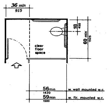
Figure 30(b) Alternate Stalls

Figure 30(c) Rear Wall of Standard Stall
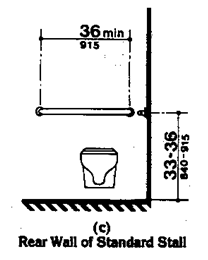
Figure 30(d) Side Walls
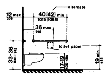
EXCEPTION: In instances of alteration work where provision of a standard stall (Fig. 30(a)) is structurally impracticable or where plumbing code requirements prevent combining existing stalls to provide space, an alternate stall (Fig. 30(b)) may be provided in lieu of the standard stall.
4.17.4 TOE CLEARANCES.
In standard stalls, the front partition and at least one side partition shall provide a toe clearance of at least 9 in (230 mm) above the floor. If the depth of the stall is greater than 60 in (1525 mm), then the toe clearance is not required.
4.17.5* DOORS.
Toilet stall doors shall comply with 4.13. If toilet stall approach is from the latch side of the stall door, clearance between the door side of the stall and any obstruction may be reduced to a minimum of 42 in (1065 mm).
4.17.6 GRAB BARS.
Grab bars complying with the length and positioning shown in Fig. 30(a), (b), (c), and (d) shall be provided. Grab bars may be mounted with any desired method as long as they have a gripping surface at the locations shown and do not obstruct the required clear floor area. Grab bars shall comply with 4.26.
4.18.1 GENERAL.
Accessible urinals shall comply with 4.18.
4.18.2 HEIGHT.
Urinals shall be stall-type or wall-hung with an elongated rim at a maximum of 17 in (430 mm) above the floor.
4.18.3 CLEAR FLOOR SPACE.
A clear floor space 30 in by 48 in (760 mm by 1220 mm) shall be provided in front of urinals to allow forward approach. This clear space shall adjoin or overlap an accessible route and shall comply with 4.2.4. Urinal shields that do not extend beyond the front edge of the urinal rim may be provided with 29 in (735 mm) clearance between them.
4.18.4 FLUSH CONTROLS.
Flush controls shall be hand operated or automatic, and shall comply with 4.27.4, and shall be mounted no more than 44 in (1120 mm) above the floor.
4.19.1 GENERAL.
The requirements of 4.19 shall apply to lavatory fixtures, vanities, and built-in lavatories.
4.19.2 HEIGHT AND CLEARANCES.
Lavatories shall be mounted with the rim or counter surface no higher than 34 in (865 mm) above the finished floor. Provide a clearance of at least 29 in (735 mm) from the floor to the bottom of the apron. Knee and toe clearance shall comply with Fig. 31.
Figure 31 Lavatory Clearances
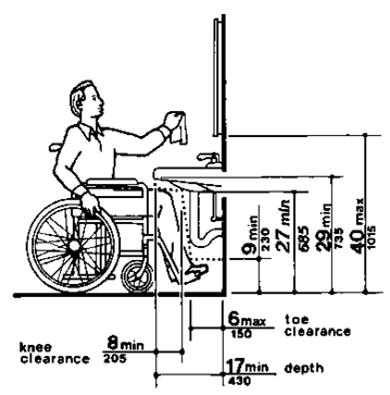
4.19.3 CLEAR FLOOR SPACE.
A clear floor space 30 in by 48 in (760 mm by 1220 mm) complying with 4.2.4 shall be provided in front of a lavatory to allow forward approach. Such clear floor space shall adjoin or overlap an accessible route and shall extend a maximum of 19 in (485 mm) underneath the lavatory (see Fig. 32).
Figure 32 Clear Floor Space at Lavatories

4.19.4 EXPOSED PIPES AND SURFACES.
Hot water and drain pipes under lavatories shall be insulated or otherwise covered. There shall be no sharp or abrasive surfaces under lavatories.
4.19.5 FAUCETS.
Faucets shall comply with 4.27.4. Lever-operated, push-type, and electronically controlled mechanisms are examples of acceptable designs. Self-closing valves are allowed if the faucet remains open for at least 10 seconds.
4.19.6* MIRRORS.
Mirrors shall be mounted with the bottom edge of the reflecting surface no higher than 40 in (1015 mm) from the floor (see Fig. 31).
4.20.1 GENERAL.
Accessible bathtubs shall comply with 4.20. For bathtubs in accessible dwelling units, see 4.34.5.4.
4.20.2 FLOOR SPACE.
Clear floor space in front of bathtubs shall be as shown in Fig. 33.
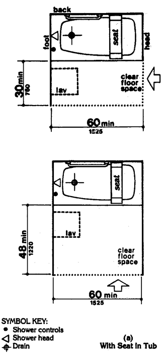
Figure 33 Clear Floor Space at Bathtubs
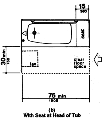
4.20.3 SEAT.
An in-tub seat or a seat at the head end of the tub shall be provided as shown in Fig. 33 and 34. The structural strength of seats and their attachments shall comply with 4.26.3. Seats shall be mounted securely and shall not slip during use.
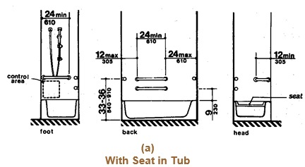
Figure 34 Grab Bars at Bathtubs
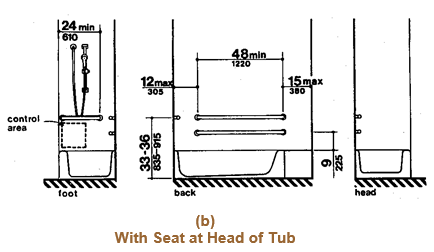
4.20.4 GRAB BARS.
Grab bars complying with 4.26 shall be provided as shown in Fig. 33 and 34.
4.20.5 CONTROLS.
Faucets and other controls complying with 4.27.4 shall be located as shown in Fig. 34.
4.20.6 SHOWER UNIT.
A shower spray unit with a hose at least 60 in (1525 mm) long that can be used as a fixed shower head or as a hand-held shower shall be provided.
4.20.7 BATHTUB ENCLOSURES.
If provided, enclosures for bathtubs shall not obstruct controls or transfer from wheelchairs onto bathtub seats or into tubs. Enclosures on bathtubs shall not have tracks mounted on their rims.
Accessible shower stalls shall comply with 4.21. For shower stalls in accessible dwelling units, see 4.34.5.5.
4.21.2 SIZE AND CLEARANCES.
Shower stall size and clear floor space shall comply with Fig. 35(a) or (b). The shower stall in Fig. 35(a) shall be 36 in by 36 in (915 mm by 915 mm). The shower stall in Fig. 35(b) will fit into the space required for a bathtub.
Figure 35
Shower Size and Clearances
Figure 35(a) Shower Size and Clearances 36-in by 36-in (915-mm by 915-mm) Stall
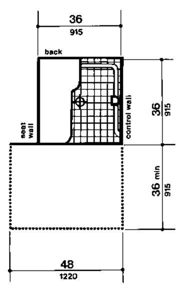
Figure 35(b) Shower Size and Clearances 30-in by 60-in (760-mm by 1525-mm) Stall
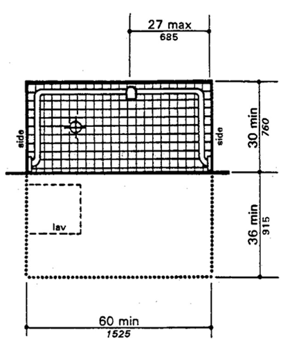
4.21.3 SEAT.
A seat shall be provided in shower stalls 36 in by 36 in (915 mm by 915 mm) and shall be as shown in Fig. 36. The seat shall be mounted 17 in to 19 in (430 mm to 485 mm) from the bathroom floor and shall extend the full depth of the stall. The seat shall be on the wall opposite the controls. The structural strength of seats and their attachments shall comply with 4.26.3.
Figure 36 Shower Seat Design
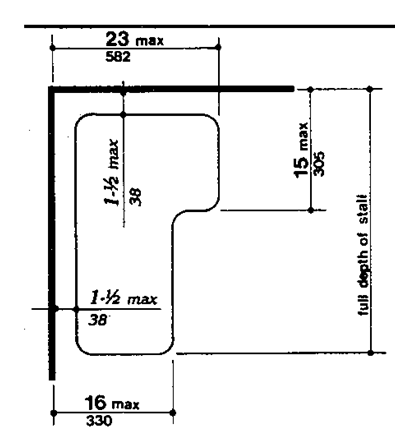
4.21.4 GRAB BARS.
Grab bars complying with 4.26 shall be provided as shown in Fig. 37.
Figure 37
Grab Bars at Shower Stalls
Figure 37(a) 36 in by 36 in (915 mm by 915 mm) Stall
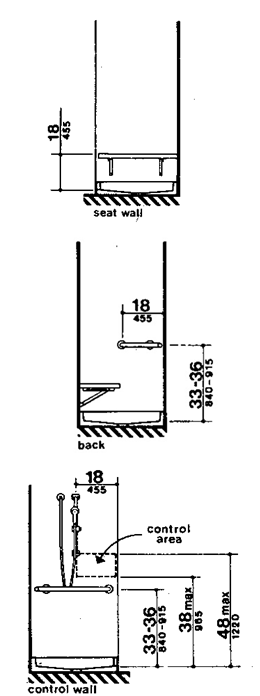
Figure 37(b) 30 in by 60 in (760 mm by 1525 mm) Stall
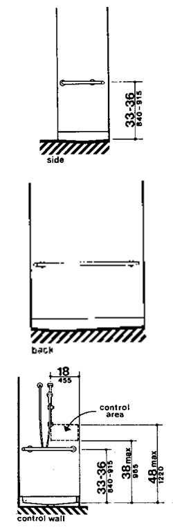
4.21.5 CONTROLS.
Faucets and other controls complying with 4.27.4 shall be located as shown in Fig. 37. In shower stalls 36 in by 36 in (915 mm by 915 mm), all controls, faucets, and the shower unit shall be mounted on the side wall opposite the seat.
4.21.6 SHOWER UNIT.
A shower spray unit with a hose at least 60 in (1525 mm) long that can be used as a fixed shower head or as a hand-held shower shall be provided.
EXCEPTION: In unmonitored facilities where vandalism is a consideration, a fixed shower head mounted at 48 in (1220 mm) above the shower floor may be used in lieu of a hand-held shower head.
4.21.7 CURBS.
If provided, curbs in shower stalls 36 in by 36 in (915 mm by 915 mm) shall be no higher than 1/2 in (13 mm). Shower stalls that are 30 in by 60 in (760 mm by 1525 mm) shall not have curbs.
4.21.8 SHOWER ENCLOSURES.
If provided, enclosures for shower stalls shall not obstruct controls or obstruct transfer from wheelchairs onto shower seats.
4.22.1 MINIMUM NUMBER.
Toilet facilities required to be accessible by 4.1 shall comply with 4.22. Accessible toilet rooms shall be on an accessible route.
4.22.2 DOORS.
All doors to accessible toilet rooms shall comply with 4.13. Doors shall not swing into the clear floor space required for any fixture.
4.22.3 CLEAR FLOOR SPACE.
The accessible fixtures and controls required in 4.22.4, 4.22.5, 4.22.6, and 4.22.7 shall be on an accessible route. An unobstructed turning space complying with 4.2.3 shall be provided within an accessible toilet room. The clear floor space at fixtures and controls, the accessible route, and the turning space may overlap.
EXCEPTION: In toilet rooms with only one water closet and one lavatory, a clear floor space of 30 in by 60 in (815 mm by 1525 mm) may be used in lieu of the unobstructed turning space.
4.22.4 WATER CLOSETS.
If toilet stalls are provided, then at least one shall comply with 4.17; its water closet shall comply with 4.16. If water closets are not in stalls, then at least one shall comply with 4.16.
4.22.5 URINALS.
If urinals are provided, then at least one shall comply with 4.18.
4.22.6 LAVATORIES AND MIRRORS.
If lavatories and mirrors are provided, then at least one of each shall comply with 4.19.
4.22.7 CONTROLS AND DISPENSERS.
If controls, dispensers, receptacles, or other equipment is provided, then at least one of each shall be on an accessible route and shall comply with 4.27.
4.23.1 MINIMUM NUMBER.
Bathrooms, bathing facilities, or shower rooms required to be accessible by 4.1 shall comply with 4.23 and shall be on an accessible route. For adaptable bathrooms in accessible dwelling units, see 4.34.5.
4.23.2 DOORS.
Doors to accessible bathrooms shall comply with 4.13. Doors shall not swing into the floor space required for any fixture.
4.23.3 CLEAR FLOOR SPACE.
The accessible fixtures and controls required in 4.23.4, 4.23.5, 4.23.6, 4.23.7, 4.23.8, and 4.23.9 shall be on an accessible route. An unobstructed turning space complying with 4.2.3 shall be provided within an accessible bathroom. The clear floor spaces at fixtures and controls, the accessible route, and the turning space may overlap.
EXCEPTION: In bathrooms with only one water closet, one lavatory, and one bathtub or shower, a clear floor space of 30 in by 60 in (760 mm by 1525 mm) may be used in lieu of the unobstructed turning space.
4.23.4 WATER CLOSETS.
If toilet stalls are provided, then at least one shall comply with 4.17; its water closet shall comply with 4.16. If water closets are not in stalls, then at least one shall comply with 4.16.
4.23.5 URINALS.
If urinals are provided, then at least one shall comply with 4.18.
4.23.6 LAVATORIES AND MIRRORS.
If lavatories and mirrors are provided, then at least one of each shall comply with 4.19.
4.23.7 CONTROLS AND DISPENSERS.
If controls, dispensers, receptacles, or other equipment is provided, then at least one of each shall be on an accessible route and shall comply with 4.27.
4.23.8 BATHING AND SHOWER FACILITIES.
If tubs or showers are provided, then at least one accessible tub that complies with 4.20 or at least one accessible shower that complies with 4.21 shall be provided.
4.23.9* MEDICINE CABINETS.
If medicine cabinets are provided, at least one shall be located with a usable shelf no higher than 44 in (1120 mm) above the floor space. The floor space shall comply with 4.2.4.
4.24.1 GENERAL.
Sinks required to be accessible by 4.1 shall comply with 4.24. Sinks in kitchens of accessible dwelling units shall comply with 4.34.6.5.
4.24.2 HEIGHT.
Sinks shall be mounted with the counter or rim no higher than 34 in (865 mm) from the floor.
4.24.3 KNEE CLEARANCE.
Knee clearance that is at least 27 in (685 mm) high, 30 in (760 mm) wide, and 19 in (485 mm) deep shall be provided underneath sinks.
4.24.4 DEPTH.
Each sink shall be a maximum of 6-1/2 in (165 mm) deep.
4.24.5 CLEAR FLOOR SPACE.
A clear floor space at least 30 in by 48 in (760 mm by 1220 mm) complying with 4.2.4 shall be provided in front of a sink to allow forward approach. The clear floor space shall be on an accessible route and shall extend a maximum of 19 in (485 mm) underneath the sink (see Fig. 32).
Figure 32 Clear Floor Space at Lavatories
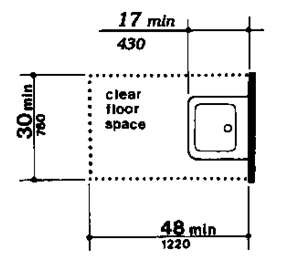
4.24.6 EXPOSED PIPES AND SURFACES.
Hot water and drain pipes exposed under sinks shall be insulated or otherwise covered. There shall be no sharp or abrasive surfaces under sinks.
4.24.7 FAUCETS.
Faucets shall comply with 4.27.4. Lever-operated, push-type, touch-type, or electronically controlled mechanisms are acceptable designs.
4.25.1 GENERAL.
Fixed storage facilities such as cabinets, shelves, closets, and drawers required to be accessible by 4.1 shall comply with 4.25.
4.25.2 CLEAR FLOOR SPACE.
A clear floor space at least 30 in by 48 in (760 mm by 1220 mm) complying with 4.2.4 that allows either a forward or parallel approach by a person using a wheelchair shall be provided at accessible storage facilities.
4.25.3 HEIGHT.
Accessible storage spaces shall be within at least one of the reach ranges specified in 4.2.5 and 4.2.6. Clothes rods shall be a maximum of 54 in (1370 mm) from the floor (see Fig. 38).
Figure 38 Storage Shelves and Closets

4.25.4 HARDWARE.
Hardware for accessible storage facilities shall comply with 4.27.4. Touch latches and U-shaped pulls are acceptable.
4.26.1* GENERAL.
All handrails, grab bars, and tub and shower seats required to be accessible by 4.1, 4.8, or 4.9 shall comply with 4.26.
4.26.2* SIZE AND SPACING OF GRAB BARS AND HANDRAILS.
The diameter or width of the gripping surfaces of a handrail or grab bar shall be 1-1/4 in to 1-1/2 in (32 mm to 38 mm), or the shape shall provide an equivalent gripping surface. If handrails or grab bars are mounted adjacent to a wall, the space between the wall and the grab bar shall be 1-1/2 in (38 mm) (see Fig. 39(a), (b), and (c)). Handrails may be located in a recess if the recess is a maximum of 3 in (75 mm) deep and extends at least 18 in (455 mm) above the top of the rail (see Fig. 39(d)).
Figure 39
Size and Spacing of Handrails and Grab Bars
Figure 39(a) Handrail
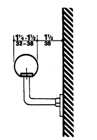
Figure 39(b) Handrail
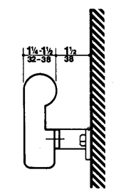
Figure 39(c) Handrail
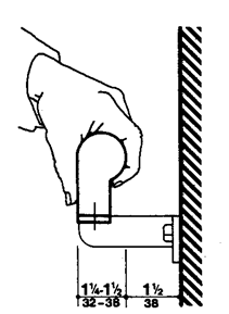
Figure 39(d) Handrail
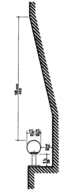
Figure 39(e) Grab Bar
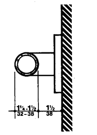
4.26.3 STRUCTURAL STRENGTH.
The structural strength of grab bars, tub and shower seats, fasteners, and mounting devices shall meet the following specification:
(1) Bending stress in a grab bar or seat induced by the maximum bending moment from the application of 250 lbf (1112N) shall be less than the allowable stress for the material of the grab bar or seat.
(2) Shear stress induced in a grab bar or seat by the application of 250 lbf (1112N) shall be less than the allowable shear stress for the material of the grab bar or seat. If the connection between the grab bar or seat and its mounting bracket or other support is considered to be fully restrained, then direct and torsional shear stresses shall be totaled for the combined shear stress, which shall not exceed the allowable shear stress.
(3) Shear force induced in a fastener or mounting device from the application of 250 lbf (1112N) shall be less than the allowable lateral load of either the fastener or mounting device or the supporting structure, whichever is the smaller allowable load.
(4) Tensile force induced in a fastener by a direct tension force of 250 lbf (1112N) plus the maximum moment from the application of 250 lbf (1112N) shall be less than the allowable withdrawal and the supporting structure.
(5) Grab bars shall not rotate within their fittings.
4.26.4 ELIMINATING HAZARDS.
A handrail or grab bar and any wall or other surface adjacent to it shall be free of any sharp or abrasive elements. Edges shall have a minimum radius of 1/8 in (3.2 mm).
4.27.1 GENERAL.
Controls and operating mechanisms required to be accessible by 4.1 shall comply with 4.27.
4.27.2 CLEAR FLOOR SPACE.
Clear floor space complying with 4.2.4 that allows a forward or a parallel approach by a person using a wheelchair shall be provided at controls, dispensers, receptacles, and other operable equipment.
4.27.3* HEIGHT.
The highest operable part of all controls, dispensers, receptacles, and other operable equipment shall be placed within at least one of the reach ranges specified in 4.2.5 and 4.2.6. Except where the use of special equipment dictates otherwise, electrical and communications system receptacles on walls shall be mounted no less than 15 in (380 mm) above the floor.
4.27.4 OPERATION.
Controls and operating mechanisms shall be operable with one hand and shall not require tight grasping, pinching, or twisting of the wrist. The force required to activate controls shall be no greater than 5 lbf (22.2 N).
4.28.1 GENERAL.
Alarm systems required to be accessible by 4.1 shall comply with 4.28.
4.28.2* AUDIBLE ALARMS.
If provided, audible emergency alarms shall produce a sound that exceeds the prevailing equivalent sound level in the room or space by at least 15 decibels or exceeds any maximum sound level with a duration of 30 seconds by 5 decibels, whichever is louder. Sound levels for alarm signals shall not exceed 120 decibels.
4.28.3* VISUAL ALARMS.
If provided, electrically powered internally illuminated emergency exit signs shall flash as a visual emergency alarm in conjunction with audible emergency alarms. The flashing frequency of visual alarm devices shall be less than 5 Hz. If such alarms use electricity from the building as a power source, then they shall be installed on the same system as the audible emergency alarms.
EXCEPTIONS:
(1) Visual alarm devices that are mounted adjacent to emergency exit signs may be used in lieu of flashing exit signs.
(2) Specialized systems utilizing advanced technology may be substituted for the visual systems specified above if equivalent protection is afforded handicapped users of the building or facility.
4.28.4* AUXILIARY ALARMS.
Accessible sleeping accommodations shall have a visual alarm connected to the building emergency alarm system or shall have a standard 110-volt electrical receptacle into which such an alarm could be connected. Instructions for use of the auxiliary alarm or connection shall be provided.
4.29.1 GENERAL.
Tactile warnings required to be accessible by 4.1 shall comply with 4.29.
4.29.2* TACTILE WARNINGS ON WALKING SURFACES.
(Reserved).
4.29.3* TACTILE WARNINGS ON DOORS TO HAZARDOUS AREAS.
Doors that lead to areas that might prove dangerous to a blind person (for example, doors to loading platforms, boiler rooms, stages, and the like) shall be made identifiable to the touch by a textured surface on the door handle, knob, pull or other operating hardware. This textured surface may be made by knurling or roughing or by a material applied to the contact surface. Such textured surfaces shall not be provided for emergency exit doors or any doors other than those to hazardous areas.
4.29.4 TACTILE WARNINGS AT STAIRS.
(Reserved).
4.29.6* TACTILE WARNINGS AT REFLECTING POOLS.
(Reserved).
4.29.7* STANDARDIZATION.
Textured surfaces for tactile door warnings shall be standard within a building, facility, site, or complex of buildings.
4.30.1* GENERAL.
Signage required to be accessible by 4.1 shall comply with 4.30.
4.30.2* CHARACTER PROPORTION.
Letters and numbers on signs shall have a width-to-height ratio between 3:5 and 1:1 and a stroke width-to-height ratio between 1:5 and 1:10.
4.30.3* COLOR CONTRAST.
Characters and symbols shall contrast with their background - either light characters on a dark background or dark characters on a light background.
4.30.4* RAISED CHARACTERS OR SYMBOLS.
Letters and numbers on signs shall be raised 1/32 in (0.8 mm) minimum and shall be sans serif characters. Raised characters or symbols shall be at least 5/8 in (16 mm) high, but no higher than 2 in (50 mm). Symbols or pictographs on signs shall be raised 1/32 in (0.8 mm) minimum.
4.30.5 SYMBOLS OF ACCESSIBILITY.
Accessible facilities required to be identified by 4.1, shall use the international symbol of accessibility. The symbol shall be displayed as shown in Fig. 43.
Figure 43
International Symbol of Accessibility
Figure 43(a) Proportions
Figure 43(b) Display Conditions
4.30.6 MOUNTING LOCATION AND HEIGHT.
Interior signage shall be located alongside the door on the latch side and shall be mounted at a height of between 54 in and 66 in (1370 mm and 1675 mm) above the finished floor.
4.31.1 GENERAL.
Public telephones required to be accessible by 4.1 shall comply with 4.31.
4.31.2 CLEAR FLOOR OR GROUND SPACE.
A clear floor or ground space at least 30 in by 48 in (760 mm by 1220 mm) that allows either a forward or parallel approach by a person using a wheelchair shall be provided at telephones (see Fig. 44). The clear floor or ground space shall comply with 4.2.4. Bases, enclosures, and fixed seats shall not impede approaches to telephones by people who use wheelchairs.
Figure 44
Mounting Heights and Clearances for Telephones
* Height to highest operable parts which are essential to basic operation of telephone
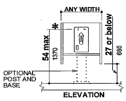
Figure 44(a) Side Reach Possible
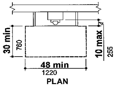
* Height to highest operable parts which are essential to basic operation of telephone
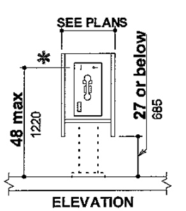
Figure 44(b) Forward Reach Required
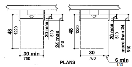
4.31.3* MOUNTING HEIGHT.
The highest operable part of the telephone shall be within the reach ranges specified in 4.2.5 or 4.2.6.
4.31.4 PROTRUDING OBJECTS.
Telephones shall comply with 4.4.
4.31.5* EQUIPMENT FOR HEARING IMPAIRED PEOPLE.
Telephones shall be equipped with a receiver that generates a magnetic field in the area of the receiver cap. Volume controls shall be provided in accordance with 4.1.2.
4.31.6 CONTROLS.
Telephones shall have pushbutton controls where service for such equipment is available.
4.31.7 TELEPHONE BOOKS.
Telephone books, if provided, shall be located in a position that complies with the reach ranges specified in 4.2.5 and 4.2.6.
4.31.8 CORD LENGTH.
The cord from the telephone to the handset shall be at least 29 in (735 mm) long.
4.32.1 MINIMUM NUMBER.
Fixed or built-in seating, tables, or work surfaces required to be accessible by 4.1 shall comply with 4.32.
4.32.2 SEATING.
If seating spaces for people in wheelchairs are provided at tables, counters, or work surfaces, clear floor space complying with 4.2.4 shall be provided. Such clear floor space shall not overlap knee space by more than 19 in (485 mm) (see Fig. 45).
Figure 45 Minimum Clearances for Seating and Tables
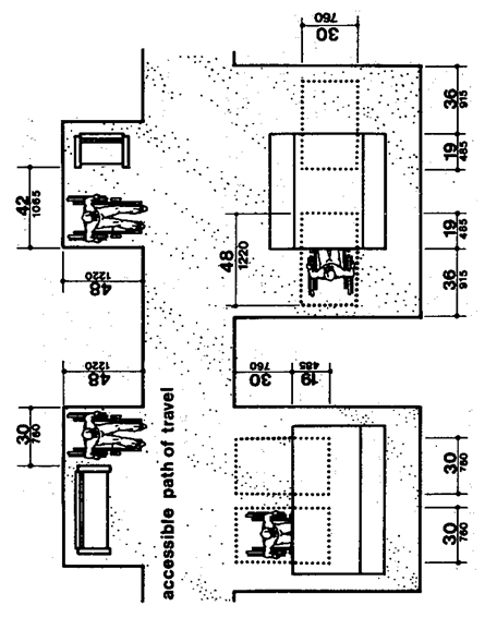
4.32.3 KNEE CLEARANCES.
If seating for people in wheelchairs is provided at tables, counters, and work surfaces, knee spaces at least 27 in (685 mm) high, 30 in (760 mm) wide, and 19 in (485 mm) deep shall be provided (see Fig. 45).
4.32.4* HEIGHT OF WORK SURFACES.
The tops of tables and work surfaces shall be from 28 in to 34 in (710 mm to 865 mm) from the floor or ground.
4.33.1 MINIMUM NUMBER.
Assembly and associated areas required to be accessible by 4.1 shall comply with 4.33.
4.33.2* SIZE OF WHEELCHAIR LOCATIONS.
Each wheelchair location shall provide minimum clear ground or floor spaces as shown in Fig. 46.
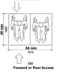
Figure 46 Space Requirements for Wheelchair Seating Spaces in Series
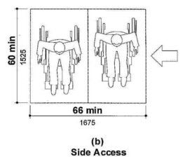
4.33.3* PLACEMENT OF WHEELCHAIR LOCATIONS.
Wheelchair areas shall be an integral part of any fixed seating plan and shall be dispersed throughout the seating area. They shall adjoin an accessible route that also serves as a means of egress in case of emergency and shall be located to provide lines of sight comparable to those for all viewing areas.
EXCEPTION: Accessible viewing positions may be clustered for bleachers, balconies, and other areas having sight lines that require slopes of greater than 5 percent. Equivalent accessible viewing positions may be located on levels having accessible egress.
4.33.4 SURFACES.
The ground or floor at wheelchair locations shall be level and shall comply with 4.5.
4.33.5 ACCESS TO PERFORMING AREAS.
An accessible route shall connect wheelchair seating locations with performing areas, including stages, arena floors, dressing rooms, locker rooms, and other spaces used by performers.
4.33.6* PLACEMENT OF LISTENING SYSTEMS.
If the listening system provided serves individual fixed seats, then such seats shall be located within a 50 ft (15 m) viewing distance of the stage or playing area and shall have a complete view of the stage or playing area.
4.33.7* TYPES OF LISTENING SYSTEMS.
Audio loops and radio frequency systems are two acceptable types of listening systems.
4.34.1 GENERAL.
The requirements of 4.34 apply to dwelling units required to be accessible by 4.1.
4.34.2* MINIMUM REQUIREMENTS.
An accessible dwelling unit shall be on an accessible route. An accessible dwelling unit shall have the following accessible elements and spaces as a minimum:
(1) Common spaces and facilities serving individual accessible dwelling units (for example, entry walks, trash disposal facilities, and mail boxes) shall comply with 4.2 through 4.33.
(2) Accessible spaces shall have maneuvering space complying with 4.2.2 and 4.2.3 and surfaces complying with 4.5.
(3) At least one accessible route complying with 4.3 shall connect the accessible entrances with all accessible spaces and elements within the dwelling units.
(4) See 4.1.1(5)(d) — Parking.
(5) Removed and reserved.
(6) Doors to and in accessible spaces that are intended for passage shall comply with 4.13, except that the provisions of 4.13.9 apply only to the doors at accessible entrances to the unit itself.
(7) At least one accessible entrance to the dwelling unit shall comply with 4.14.
(8) Storage in accessible spaces in dwelling units, including cabinets, shelves, closets, and drawers, shall comply with 4.25.
(9) All controls in accessible spaces shall comply with 4.27. Those portions of heating, ventilating, and air conditioning equipment requiring regular, periodic maintenance and adjustment by the resident of a dwelling shall be accessible to people in wheelchairs. If air distribution registers must be placed in or close to ceilings for proper air circulation, this specification shall not apply to the registers.
(10) Emergency alarms as required by 4.1 and complying with 4.28.4 shall be provided in the dwelling unit.
(11) Removed and reserved.
(12) At least one full bathroom shall comply with 4.34.5. A full bathroom shall include a water closet, a lavatory, and a bathtub or a shower.
(13) The kitchen shall comply with 4.34.6.
(14) If laundry facilities are provided, they shall comply with 4.34.7.
(15) The following spaces shall be accessible and shall be on an accessible route:
(a) The living area.
(b) The dining area.
(c) The sleeping area, or the bedroom in one bedroom dwelling units, or at least two bedrooms or sleeping spaces in dwelling units with two or more bedrooms.
(d) Patios, terraces, balconies, carports, and garages, if provided with the dwelling unit.
4.34.3 ADAPTABILITY.
The specifications for 4.34.5 and 4.34.6 include the concept of adaptability. Accessible dwelling units may be designed for either permanent accessibility or adaptability.
4.34.4 CONSUMER INFORMATION.
To ensure that the existence of adaptable features will be known to the owner or occupant of a dwelling, the following consumer information shall be provided in each adaptable dwelling unit available for occupancy:
(1) Notification of the alternate heights available for the kitchen counter and sink, and the existence of removable cabinets and bases, if provided, under counters, sinks, and lavatories.
(2) Notification of the provisions for the installation of grab bars at toilets, bathtubs, and showers.
(3) Notification that the dwelling unit is equipped to have a visual emergency alarm installed.
(4) Identification of the location where information and instructions are available for changing the height of counters, removing cabinets and bases, installing a visual emergency alarm system, and installing grab bars.
(5) Notification that the dwelling unit has been designed in accordance with this Uniform Federal Accessibility Standards.
In addition, the parties who will be responsible for making adaptations shall be provided with the following information:
(1) Instructions for adjusting or replacing kitchen counter and sink heights and for removing cabinets.
(2) A scale drawing showing methods and locations for the installation of grab bars.
(3) A scale drawing showing the location of adjustable or replaceable counter areas and removable cabinets.
(4) Identification of the location of any equipment and parts required for adjusting or replacing counter tops, cabinets, and sinks.
(5) Instructions for installing a visual emergency alarm system, if the dwelling unit is equipped for such an installation.
4.34.5* BATHROOMS.
Accessible or adaptable bathrooms shall be on an accessible route and shall comply with the requirements of 4.34.5.
4.34.5.1 DOORS.
Doors shall not swing into the clear floor space required for any fixture.
(1) Clear floor space at the water closet shall be as shown in Fig. 47(a). The water closet may be located with the clear area at either the right or left side of the toilet.
(2) The height of the water closet shall be at least 15 in (380 mm), and no more than 19 in (485 mm), measured to the top of the toilet seat.
(3) Structural reinforcement or other provisions that will allow installation of grab bars shall be provided in the locations shown in Fig. 47(b). If provided, grab bars shall be installed as shown in Fig. 29 and shall comply with 4.26.
(4) The toilet paper dispenser shall be installed within reach as shown in Fig. 47(b).
Figure 47
Water Closets in Adaptable Bathrooms
Figure 47(a) Clear Floor Space for Adaptable Bathrooms
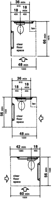
Figure 47(b) Reinforced Areas for Installation of Grab Bars Note: The hatched areas are reinforced to receive grab bars.
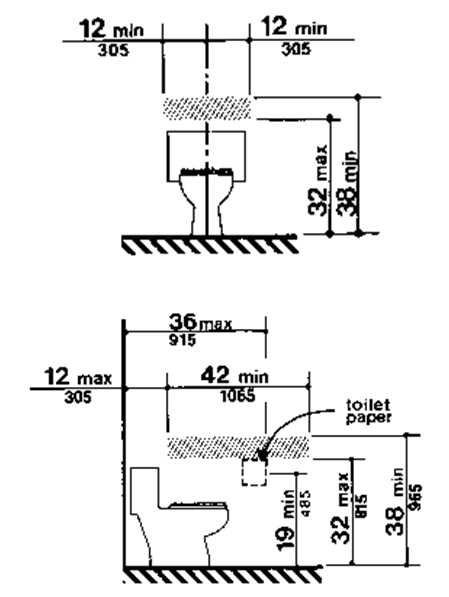
4.34.5.3 LAVATORY, MIRRORS, AND MEDICINE CABINETS.
(1) The lavatory and mirrors shall comply with 4.22.6.
(2) If a cabinet is provided under the lavatory in adaptable bathrooms, then it shall be removable to provide the clearances specified in 4.22.6.
(3) If a medicine cabinet is provided above the lavatory, then the bottom of the medicine cabinet shall be located with a usable shelf no higher than 44 in (1120 mm) above the floor.
4.34.5.4 BATHTUBS.
If a bathtub is provided, then it shall have the following features:
4.34.5.4(1) Floor space.
(1) Floor space. Clear floor space at bathtubs shall be as shown in Fig. 33.
4.34.5.4(2) Seat.
(2) Seat. An in-tub seat or a seat at the head end of the tub shall be provided as shown in Fig. 33 and 34. The structural strength of seats and their attachments shall comply with 4.26.3. Seats shall be mounted securely and shall not slip during use.
4.34.5.4(3) Grab bars.
(3) Grab bars. Structural reinforcement or other provisions that will allow installation of grab bars shall be provided in the locations shown in Fig. 48. If provided, grab bars shall be installed as shown in Fig. 34 and shall comply with 4.26.
4.34.5.4(4) Controls.
(4) Controls. Faucets and other controls shall be located as shown in Fig. 34 and shall comply with 4.27.4.
4.34.5.4(5) Shower unit.
(5) Shower unit. A shower spray unit with a hose at least 60 in (1525 mm) long that can be used as a fixed shower head or as a hand-held shower shall be provided.
Figure 48
Location of Grab Bars and Controls of Adaptable Bathtubs
Figure 48(a) With Seat in Tub Note: The hatched areas are reinforced to receive grab bars.
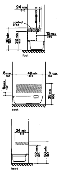
Figure 48(b) With Seat at Head of Tub Note: The hatched areas are reinforced to receive grab bars.
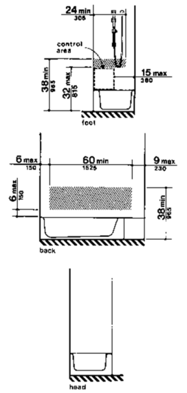
4.34.5.5 SHOWERS.
If a shower is provided, it shall have the following features:
4.34.5.5(1) Size and clearances.
(1) Size and clearances. Shower stall size and clear floor space shall comply with either Fig. 35(a) or (b). The shower stall in Fig. 35(a) shall be 36 in by 36 in (915 mm by 915 mm). The shower stall in Fig. 35(b) will fit into the same space as a standard 60 in (1525 mm) long bathtub.
4.34.5.5(2) Seat.
(2) Seat. A seat shall be provided in the shower stall in Fig. 35(a) as shown in Fig. 36. The seat shall be 17 in to 19 in (430 mm to 485 mm) high measured from the bathroom floor and shall extend the full depth of the stall. The seat shall be on the wall opposite the controls. The structural strength of seats and their attachments shall comply with 4.26.3. Seats shall be mounted securely and shall not slip during use.
4.34.5.5(3) Grab bars.
(3) Grab bars. Structural reinforcement or other provisions that will allow installation of grab bars shall be provided in the locations shown in Fig. 49. If provided, grab bars shall be installed as shown in Fig. 37 and shall comply with 4.26.
4.34.5.5(4) Controls.
(4) Controls. Faucets and other controls shall be located as shown in Fig. 37 and shall comply with 4.27.4. In the shower stall in Fig. 35(a), all controls, faucets, and the shower unit shall be mounted on the side wall opposite the seat.
4.34.5.5(5) Shower unit.
(5) Shower unit. A shower spray unit with a hose at least 60 in (1525 mm) long that can be used as a fixed shower head at various heights or as a hand-held shower shall be provided.
Figure 49
Location of Grab Bars and Controls of Adaptable Showers
Figure 49(a) 36-in by 36-in Stall Note: The hatched areas are reinforced to receive grab bars.
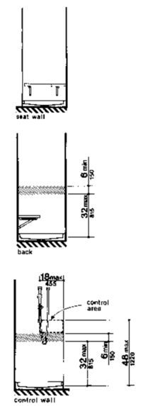
Figure 49(b) 30-in by 60-in Stall Note: The hatched areas are reinforced to receive grab bars.
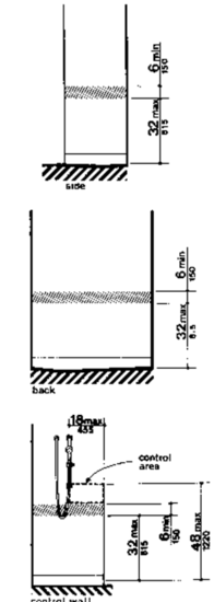
4.34.5.6 BATHTUB AND SHOWER ENCLOSURES.
Enclosures for bathtubs or shower stalls shall not obstruct controls or transfer from wheelchairs onto shower or bathtub seats. Enclosures on bathtubs shall not have tracks mounted on their rims.
4.34.5.7 CLEAR FLOOR SPACE.
Clear floor space at fixtures may overlap.
4.34.6 KITCHENS.
Accessible or adaptable kitchens and their components shall be on an accessible route and shall comply with the requirements of 4.34.6.
4.34.6.1* CLEARANCE.
Clearances between all opposing base cabinets, counter tops, appliances, or walls shall be 40 in (1015 mm) minimum, except in U-shaped kitchens, where such clearance shall be 60 in (1525 mm) minimum.
4.34.6.2 CLEAR FLOOR SPACE.
A clear floor space at least 30 in by 48 in (760 mm by 1220 mm) complying with 4.2.4 that allows either a forward or a parallel approach by a person in a wheelchair shall be provided at all appliances in the kitchen, including the range or cooktop, oven, refrigerator/freezer, dishwasher, and trash compactor. Laundry equipment located in the kitchen shall comply with 4.34.7.
4.34.6.3 CONTROLS.
All controls in kitchens shall comply with 4.27.
4.34.6.4 WORK SURFACES.
At least one 30 in (760 mm) section of counter shall provide a work surface that complies with the following requirements (see Fig. 50):
(1) The counter shall be mounted at a maximum height of 34 in (865 mm) above the floor, measured from the floor to the top of the counter surface, or shall be adjustable or replaceable as a unit to provide alternative heights of 28 in, 32 in, and 36 in (710 mm, 815 mm, and 915 mm), measured from the top of the counter surface.
(2) Base cabinets, if provided, shall be removable under the full 30 in (760 mm) minimum frontage of the counter. The finished floor shall extend under the counter to the wall.
(3) Counter thickness and supporting structure shall be 2 in (50 mm) maximum over the required clear area.
(4) A clear floor space 30 in by 48 in (760 mm by 1220 mm) shall allow a forward approach to the counter. Nineteen inches (485 mm) maximum of the clear floor space may extend underneath the counter. The knee space shall have a minimum clear width of 30 in (760 mm) and a minimum clear depth of 19 in (485 mm).
(5) There shall be no sharp or abrasive surfaces under such counters.
Figure 50
Counter Work Surface
Figure 50(a) Before Removal of Cabinets and Base
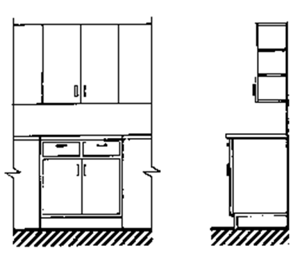
Figure 50(b) Cabinets and Base Removed and Height Alternatives
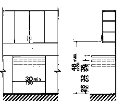
4.34.6.5* SINK.
The sink and surrounding counter shall comply with the following requirements (see Fig. 51):
(1) The sink and surrounding counter shall be mounted at a maximum height of 34 in (865 mm) above the floor, measured from the floor to the top of the counter surface, or shall be adjustable or replaceable as a unit to provide alternative heights of 28 in, 32 in, and 36 in (710 mm, 815 mm, and 915 mm), measured from the floor to the top of the counter surface or sink rim. The total width of sink and counter area shall be 30 in (760 mm).
(2) Rough-in plumbing shall be located to accept connections of supply and drain pipes for sinks mounted at the height of 28 in (710 mm).
(3) The depth of a sink bowl shall be no greater than 6-1/2 in (165 mm). Only one bowl of double- or triple-bowl sinks needs to meet this requirement.
(4) Faucets shall comply with 4.27.4. Lever-operated or push-type mechanisms are two acceptable designs.
(5) Base cabinets, if provided, shall be removable under the full 30 in (760 mm) minimum frontage of the sink and surrounding counter. The finished flooring shall extend under the counter to the wall.
(6) Counter thickness and supporting structure shall be 2 in (50 mm) maximum over the required clear space.
(7) A clear floor space 30 in by 48 in (760 mm by 1220 mm) shall allow forward approach to the sink. Nineteen inches (485 mm) maximum of the clear floor space may extend underneath the sink. The knee space shall have a clear width of 30 in (760 mm) and a clear depth of 19 in (485 mm).
(8) There shall be no sharp or abrasive surfaces under sinks. Hot water and drain pipes under sinks shall be insulated or otherwise covered.
Figure 51
Kitchen Sink
Figure 51(a) Before Removal of Cabinets and Base
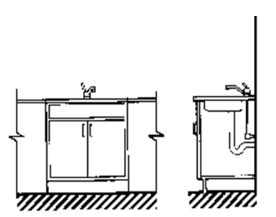
Figure 51(b) Cabinets and Base Removed and Height Alternatives
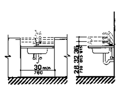
4.34.6.6* RANGES AND COOKTOPS.
Ranges and cooktops shall comply with 4.34.6.2 and 4.34.6.3. If ovens or cooktops have knee spaces underneath, then they shall be insulated or otherwise protected on the exposed contact surfaces to prevent burns, abrasions, or electrical shock. The clear floor space may overlap the knee space, if provided, by 19 in (485 mm) maximum. The location of controls for ranges and cook-tops shall not require reaching across burners.
4.34.6.7* OVENS.
Ovens shall comply with 4.34.6.2 and 4.34.6.3. Ovens shall be of the self-cleaning type or be located adjacent to an adjustable height counter with knee space below (see Fig. 52). For side-opening ovens, the door latch side shall be next to the open counter space, and there shall be a pull-out shelf under the oven extending the full width of the oven and pulling out not less than 10 in (255 mm) when fully extended. Ovens shall have controls on front panels; they may be located on either side of the door.
Figure 52
Ovens without Self-Cleaning Feature
Figure 52(a) Side-hinged Door
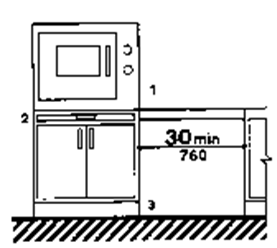
Figure 52(b) Bottom-hinged Door
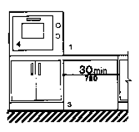
SYMBOL KEY
1. Countertop or wall-mounted oven
2. Pull-out board preferred with side-opening door.
3. Clear open space.
4. Bottom-hinged door
4.34.6.8* REFRIGERATOR/FREEZER.
Refrigerator/freezers shall comply with 4.34.6.3. Provision shall be made for refrigerators which are:
(1) Of the vertical side-by-side refrigerator/freezer type; or
(2) Of the over-and-under type and meet the following requirements:
(a) Have at least 50 percent of the freezer space below 54 in (1370 mm) above the floor.
(b) Have 100 percent of the refrigerator space and controls below 54 in (1370 mm).
Freezers with less than 100 percent of the storage volume within the limits specified in 4.2.5 or 4.2.6 shall be the self-defrosting type.
Dishwashers shall comply with 4.34.6.2 and 4.34.6.3. Dishwashers shall have all rack space accessible from the front of the machine for loading and unloading dishes.
4.34.6.10* KITCHEN STORAGE.
Cabinets, drawers, and shelf areas shall comply with 4.25 and shall have the following features:
(1) Maximum height shall be 48 in (1220 mm) for at least one shelf of all cabinets and storage shelves mounted above work counters (see Fig. 50).
(2) Door pulls or handles for wall cabinets shall be mounted as close to the bottom of cabinet doors as possible. Door pulls or handles for base cabinets shall be mounted as close to the top of cabinet doors as possible.
4.34.7 LAUNDRY FACILITIES.
If laundry equipment is provided within individual accessible dwelling units, or if separate laundry facilities serve one or more accessible dwelling units, then they shall meet the requirements of 4.34.7.1 through 4.34.7.3.
4.34.7.1 LOCATION.
Laundry facilities and laundry equipment shall be on an accessible route.
4.34.7.2 WASHING MACHINES AND CLOTHES DRYERS.
Washing machines and clothes dryers in common use laundry rooms shall be front loading.
4.34.7.3 CONTROLS.
Laundry equipment shall comply with 4.27.
User Comments/Questions
Add Comment/Question