2013 California Standards for Accessible Design Pocket Guide
DIVISION 3: BUILDING BLOCKS
11B-301.1 Scope.
The provisions of Division 3 shall apply where required by Division 2 or where referenced by a requirement in this chapter.
11B-302.1 General.
Floor and ground surfaces shall be stable, firm, and slip resistant and shall comply with 11B-302.
Exceptions:
1. Within animal containment areas, floor and ground surfaces shall not be required to be stable, firm, and slip resistant.
2. Areas of sport activity shall not be required to comply with 11B-302.

Additional information regarding accessible exterior surfaces is available on the US Access Board website at http://www.access-board.gov/research/completed-research/accessible-exterior-surfaces. ◼
11B-302.2 Carpet.
Carpet or carpet tile shall be securely attached and shall have a firm cushion, pad, or backing or no cushion or pad. Carpet or carpet tile shall have a level loop, textured loop, level cut pile, or level cut/uncut pile texture. Pile height shall be ½ inch (12.7 mm) maximum. Exposed edges of carpet shall be fastened to floor surfaces and shall have trim on the entire length of the exposed edge. Carpet edge trim shall comply with Section 11B-303 _|Changes in Level|_.

However, in addition to circumstances in which the California Building Code applies to built-in floor mats, there may also be circumstances in which Americans with Disabilities Act (ADA) requirements apply to floor mats that are not built in. If movable floor mats impede access for people with disabilities, they may need to be moved or removed under Section 36.304 of the ADA Title III regulations. That section requires that a public accommodation remove barriers in existing facilities where removing them is "readily achievable," that is, easily accomplishable and able to be carried out without much difficulty or expense. Even though the requirements of this chapter would not apply to the mats themselves, the ADA regulations can provide helpful guidance in ensuring that mats do not constitute barriers.◼
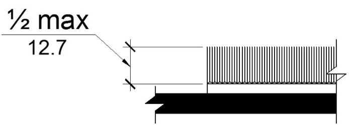
CARPET PILE HEIGHT
11B-302.3 Openings.
Openings in floor or ground surfaces shall not allow passage of a sphere more than ½ inch (12.7 mm) diameter except as allowed in Sections 11B-407.4.3 _|Platform to Hoistway Clearance|_, 11B-409.4.3 _|Platform to Hoistway Clearance|_, 11B-410.4 _|Platform to Runway Clearance|_, 11B-810.5.3 _|Platform and Vehicle Floor Coordination|_ and 11B-810.10 _|Track Crossings|_. Elongated openings shall be placed so that the long dimension is perpendicular to the dominant direction of travel.
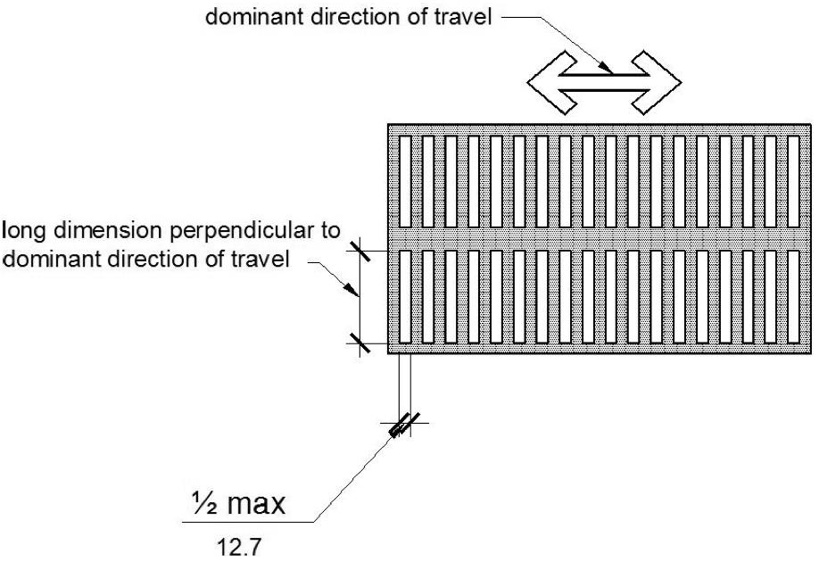
ELONGATED OPENINGS IN FLOOR OR GROUND SURFACES
11B-303.1 General.
Where changes in level are permitted in floor or ground surfaces, they shall comply with Section 11B-303.
Exceptions:
1. Animal containment areas shall not be required to comply with Section 11B-303.
2. Areas of sport activity shall not be required to comply with Section 11B-303.
11B-303.2 Vertical.
Changes in level of ¼ inch (6.4 mm) high maximum shall be permitted to be vertical and without edge treatment.
[2010 ADAS] 303.2 Vertical. Changes in level of ¼ inch high maximum shall be permitted to be vertical.
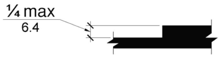
VERTICAL CHANGE IN LEVEL
11B-303.3 Beveled.
Changes in level between ¼ inch (6.4 mm) high minimum and ½ inch (12.7 mm) high maximum shall be beveled with a slope not steeper than 1:2.
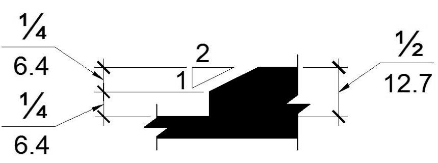
BEVELED CHANGE IN LEVEL
11B-303.4 Ramps.
Changes in level greater than ½ inch (12.7 mm) high shall be ramped, and shall comply with Section 11B-405 or 11B-406.
11B-303.5 Warning curbs.
Abrupt changes in level exceeding 4 inches (102 mm) in a vertical dimension between walks, sidewalks or other pedestrian ways and adjacent surfaces or features shall be identified by warning curbs at least 6 inches (152 mm) in height above the walk or sidewalk surface.
Exceptions:
1. A warning curb is not required between a walk or sidewalk and an adjacent street or driveway.
2. A warning curb is not required when a guard or handrail is provided with a guide rail centered 2 inches (51 mm) minimum and 4 inches (102 mm) maximum above the surface of the walk or sidewalk.
11B-304.2 Floor or Ground Surfaces.
Floor or ground surfaces of a turning space shall comply with Section 11B-302. Changes in level are not permitted.
Exception: Slopes not steeper than 1:48 shall be permitted.
11B-304.3 Size.
Turning space shall comply with Section 11B-304.3.1 or 11B-304.3.2.
11B-304.3.1 Circular space.
The turning space shall be a space of 60 inches (1524 mm) diameter minimum. The space shall be permitted to include knee and toe clearance complying with Section 11B-306.
11B-304.3.2 T-Shaped space.
The turning space shall be a T-shaped space within a 60 inch (1524 mm) square minimum with arms and base 36 inches (914 mm) wide minimum. Each arm of the T shall be clear of obstructions 12 inches (305 mm) minimum in each direction and the base shall be clear of obstructions 24 inches (610 mm) minimum. The space shall be permitted to include knee and toe clearance complying with Section 11B-306 only at the end of either the base or one arm.
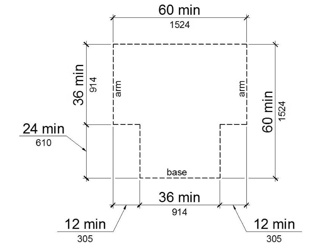
T-SHAPED TURNING SPACE
11B-304.4 Door swing.
Doors shall be permitted to swing into turning spaces.
11B-305.1 General.
Clear floor or ground space shall comply with Section 11B-305.
11B-305.2 Floor or ground surfaces.
Floor or ground surfaces of a clear floor or ground space shall comply with Section 11B-302. Changes in level are not permitted.
Exception: Slopes not steeper than 1:48 shall be permitted
11B-305.3 Size.
The clear floor or ground space shall be 30 inches (762 mm) minimum by 48 inches (1219 mm) minimum.
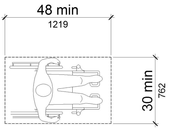
CLEAR FLOOR OR GROUND SPACE
11B-305.4 Knee and toe clearance.
Unless otherwise specified, clear floor or ground space shall be permitted to include knee and toe clearance complying with Section 11B-306.
11B-305.5 Position.
Unless otherwise specified, clear floor or ground space shall be positioned for either forward or parallel approach to an element.
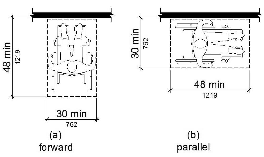
POSITION OF CLEAR FLOOR OR GROUND SPACE
11B-305.6 Approach.
One full unobstructed side of the clear floor or ground space shall adjoin an accessible route or adjoin another clear floor or ground space. Clear floor or ground space may overlap an accessible route, unless specifically prohibited elsewhere in this chapter.
11B-305.7 Maneuvering clearance.
Where a clear floor or ground space is located in an alcove or otherwise confined on all or part of three sides, additional maneuvering clearance shall be provided in accordance with Sections 11B-305.7.1 and 11B-305.7.2.
11B-305.7.1 Forward approach.
Alcoves shall be 36 inches (914 mm) wide minimum where the depth exceeds 24 inches (610 mm).
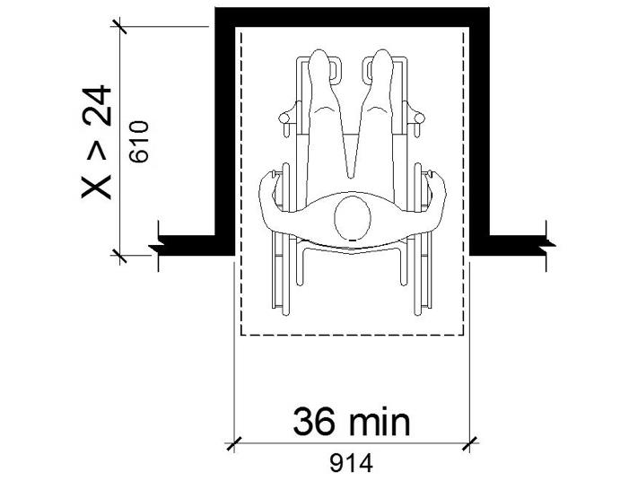
MANEUVERING CLEARANCE IN AN ALCOVE, FORWARD APPROACH
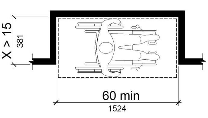
11B-305.7.2 Parallel approach.
Alcoves shall be 60 inches (1524 mm) wide minimum where the depth exceeds 15 inches (381 mm).
MANEUVERING CLEARANCE IN AN ALCOVE, PARALLEL APPROACH
11B-306.1 General.
Where space beneath an element is included as part of clear floor or ground space or turning space, the space shall comply with Section 11B-306. Additional space shall not be prohibited beneath an element but shall not be considered as part of the clear floor or ground space or turning space.
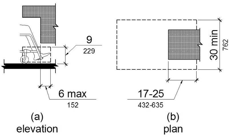
11B-306.2.1 General.
Space under an element between the finish floor or ground and 9 inches (229 mm) above the finish floor or ground shall be considered toe clearance and shall comply with Section 11B-306.2.
11B-306.2.2 Maximum depth.
Toe clearance shall extend 25 inches (635 mm) maximum under an element.
Exception: Toe clearance shall extend 19 inches (483 mm) maximum under lavatories required to be accessible by Section 11B-213.3.4.
11B-306.2.3 Minimum required depth.
Where toe clearance is required at an element as part of a clear floor space, the toe clearance shall extend 17 inches (432 mm) minimum under the element.
Exceptions:
1. The toe clearance shall extend 19 inches (483 mm) minimum under sinks required to be accessible by Section 11B-212.3.
2. The toe clearance shall extend 19 inches (483 mm) minimum under built-in dining and work surfaces required to be accessible by Section 11B-226.1.
11B-306.2.4 Additional clearance.
Space extending greater than 6 inches (152 mm) beyond the available knee clearance at 9 inches (229 mm) above the finish floor or ground shall not be considered toe clearance.
11B-306.3.1 General.
Space under an element between 9 inches (229 mm) and 27 inches (686 mm) above the finish floor or ground shall be considered knee clearance and shall comply with Section 11B-306.3.
Exception: At lavatories required to be accessible by Section 11B-213.3.4, space between 9 inches (229 mm) and 29 inches (737 mm) above the finish floor or ground, shall be considered knee clearance.
11B-306.3.2 Maximum depth.
Knee clearance shall extend 25 inches (635 mm) maximum under an element at 9 inches (229 mm) above the finish floor or ground.
11B-306.3.3 Minimum required depth.
Where knee clearance is required under an element as part of a clear floor space, the knee clearance shall be 11 inches (279 mm) deep minimum at 9 inches (229 mm) above the finish floor or ground, and 8 inches (203 mm) deep minimum at 27 inches (686 mm) above the finish floor or ground.
Exceptions:
1. At lavatories required to be accessible by Section 11B-213.3.4, the knee clearance shall be 27 inches (686 mm) high minimum above the finish floor or ground at a depth of 8 inches (203 mm) minimum increasing to 29 inches (737 mm) high minimum above the finish floor or ground at the front edge of a counter with a built-in lavatory or at the front edge of a wall-mounted lavatory fixture.
2. At dining and work surfaces required to be accessible by Section 11B-226.1, knee clearance shall extend 19 inches (483 mm) deep minimum at 27 inches (686 mm) above the finish floor or ground.
11B-306.3.4 Clearance reduction.
Between 9 inches (229 mm) and 27 inches (686 mm) above the finish floor or ground, the knee clearance shall be permitted to reduce at a rate of 1 inch (25 mm) in depth for each 6 inches (152 mm) in height.
Exception: The knee clearance shall not be reduced at built-in dining and work surfaces required to be accessible by Section 11B-226.1.
11B-306.3.5 Width.
Knee clearance shall be 30 inches (762 mm) wide minimum.
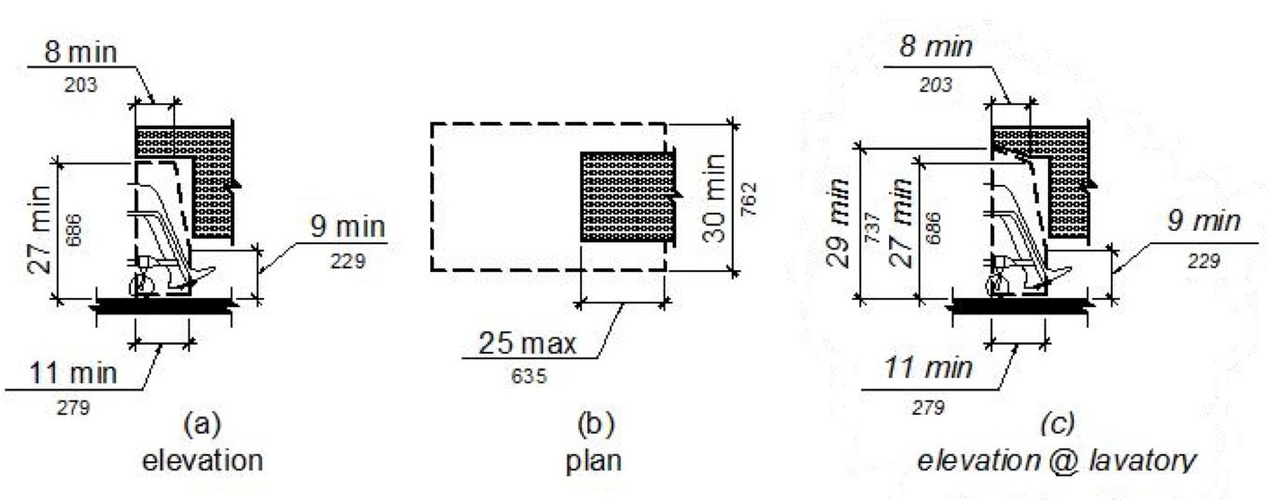
FIGURE 11B-306.3 ‡‡
KNEE CLEARANCE
11B-307.2 Protrusion limits.
Objects with leading edges more than 27 inches (686 mm) and not more than 80 inches (2032 mm) above the finish floor or ground shall protrude 4 inches (102 mm) maximum horizontally into the circulation path.
Exception: Handrails shall be permitted to protrude 4½ inches (114 mm) maximum.
LIMITS OF PROTRUDING OBJECTS
11B-307.3 Post-mounted objects.
Free-standing objects mounted on posts or pylons shall overhang circulation paths 12 inches (305 mm) maximum when located 27 inches (686 mm) minimum and 80 inches (2032 mm) maximum above the finish floor or ground. Where a sign or other obstruction is mounted between posts or pylons and the clear distance between the posts or pylons is greater than 12 inches (305 mm), the lowest edge of such sign or obstruction shall be 27 inches (686 mm) maximum or 80 inches (2032 mm) minimum above the finish floor or ground.
Exception: The sloping portions of handrails serving stairs and ramps shall not be required to comply with Section 11B-307.3.
11B-307.3.1 Edges and corners.
Where signs or other objects are mounted on posts or pylons, and their bottom edges are less than 80 inches (2032 mm) above the floor or ground surface, the edges of such signs and objects shall be rounded or eased and the corners shall have a minimum radius of 1/8 inch (3.2 mm).
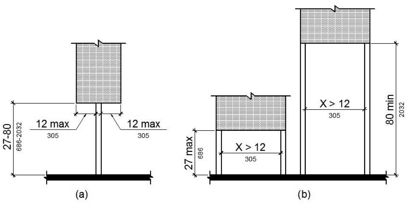
FIGURE 11B-307.3
POST-MOUNTED PROTRUDING OBJECTS
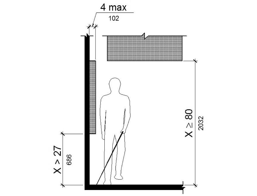
11B-307.4 Vertical clearance.
Vertical clearance shall be 80 inches (2032 mm) high minimum. Guardrails or other barriers shall be provided where the vertical clearance is less than 80 inches (2032 mm) high. The leading edge of such guardrail or barrier shall be located 27 inches (686 mm) maximum above the finish floor or ground. Where a guy support is used parallel to a circulation path, including but not limited to sidewalks, a guy brace, sidewalk guy or similar device shall be used to prevent an overhanging obstruction.
Exception: Door closers and door stops shall be permitted to be 78 inches (1981 mm) minimum above the finish floor or ground.
11B-307.4.1 Guy braces.
Where a guy support is used within either the width of a circulation path or 24 inches maximum outside of a circulation path, a vertical guy brace, sidewalk guy or similar device shall be used to prevent a hazard or an overhead obstruction.
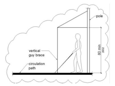
GUY BRACES
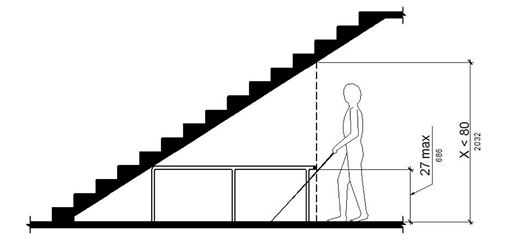
VERTICAL CLEARANCE
11B-307.5 Required clear width.
Protruding objects shall not reduce the clear width required for accessible routes.
11B-308.1 General.
Reach ranges shall comply with Section 11B-308.
|
Children's Reach Ranges |
|||
|
Forward or Side Reach |
Ages 3 and 4 |
Ages 5 through 8 |
Ages 9 through 12 |
|
High (maximum) |
36 in (915 mm) |
40 in (1015 mm) |
44 in (1120 mm) |
|
Low (minimum) |
20 in (510 mm) |
18 in (455 mm) |
16 in (405 mm) |
11B-308.1.1 Electrical switches.
Controls and switches intended to be used by the occupant of a room or area to control lighting and receptacle outlets, appliances or cooling, heating and ventilating equipment, shall comply with Section 11B-308 except the low reach shall be measured to the bottom of the outlet box and the high reach shall be measured to the top of the outlet box.
11B-308.1.2 Electrical receptacle outlets.
Electrical receptacle outlets on branch circuits of 30 amperes or less and communication system receptacles shall comply with Section 11B-308 except the low reach shall be measured to the bottom of the outlet box and the high reach shall be measured to the top of the outlet box.
11B-308.2.1 Unobstructed.
Where a forward reach is unobstructed, the high forward reach shall be 48 inches (1219 mm) maximum and the low forward reach shall be 15 inches (381 mm) minimum above the finish floor or ground.
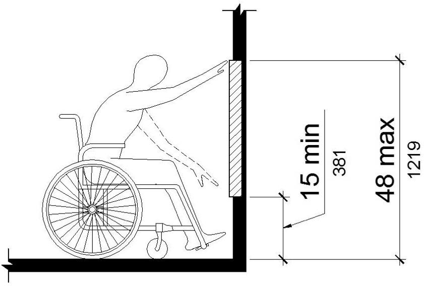
FIGURE 11B-308.2.1
UNOBSTRUCTED FORWARD REACH
11B-308.2.2 Obstructed high reach.
Where a high forward reach is over an obstruction, the clear floor space shall extend beneath the element for a distance not less than the required reach depth over the obstruction. The high forward reach shall be 48 inches (1219 mm) maximum where the reach depth is 20 inches (508 mm) maximum. Where the reach depth exceeds 20 inches (508 mm), the high forward reach shall be 44 inches (1118 mm) maximum and the reach depth shall be 25 inches (635 mm) maximum.
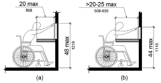
FIGURE 11B-308.2.2
OBSTRUCTED HIGH FORWARD REACH
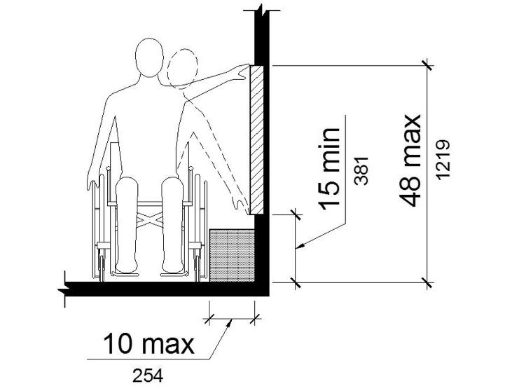
11B-308.3.1 Unobstructed.
Where a clear floor or ground space allows a parallel approach to an element and the side reach is unobstructed, the high side reach shall be 48 inches (1219 mm) maximum and the low side reach shall be 15 inches (381 mm) minimum above the finish floor or ground.
[S.H. 1118B.6] [Safe Harbor only applies to existing public telephones and coat hooks at Toilet Rooms.]
Exceptions:
1. An obstruction shall be permitted between the clear floor or ground space and the element where the depth of the obstruction is 10 inches (254 mm) maximum.
2. Operable parts of fuel dispensers shall be permitted to be 54 inches (1372 mm) maximum measured from the surface of the vehicular way where fuel dispensers are installed on existing curbs.
UNOBSTRUCTED SIDE REACH
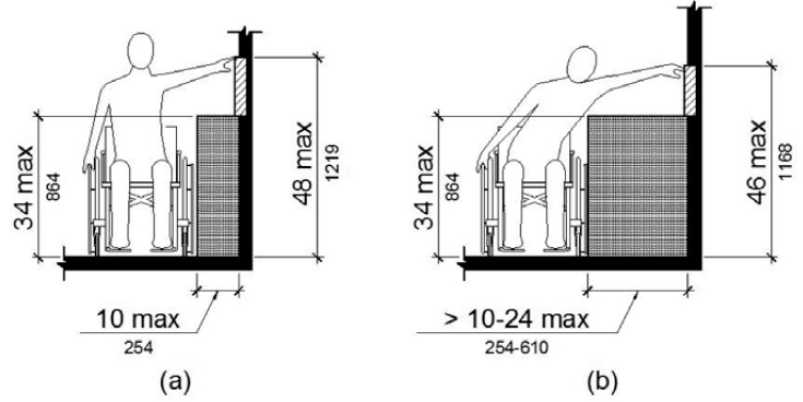
11B-308.3.2 Obstructed high reach.
Where a clear floor or ground space allows a parallel approach to an element and the high side reach is over an obstruction, the height of the obstruction shall be 34 inches (864 mm) maximum and the depth of the obstruction shall be 24 inches (610 mm) maximum. The high side reach shall be 48 inches (1219 mm) maximum for a reach depth of 10 inches (254 mm) maximum. Where the reach depth exceeds 10 inches (254 mm), the high side reach shall be 46 inches (1168 mm) maximum for a reach depth of 24 inches (610 mm) maximum.
[S.H. 1118B.6] [Safe Harbor only applies to existing public telephones and coat hooks at Toilet Rooms.]
Exceptions:
1. The top of washing machines and clothes dryers shall be permitted to be 36 inches (914 mm) maximum above the finish floor.
2. Operable parts of fuel dispensers shall be permitted to be 54 inches (1372 mm) maximum measured from the surface of the vehicular way where fuel dispensers are installed on existing curbs.
OBSTRUCTED HIGH SIDE REACH
11B-308.4 Suggested reach ranges for children.
Where building elements such as coat hooks, lockers, or operable parts are designed for use primarily by children, the suggested dimensions of Table 11B-308.4 shall be permitted. These dimensions apply to either forward or side reaches.
TABLE 11B-308.4 SUGGESTED DIMENSIONS FOR CHILDREN'S USE
|
SUGGESTED REACH RANGES FOR CHILDREN AGES 3 THROUGH 12 |
|||
|
Forward or Side Reach |
Ages 3 and 4 |
Ages 5 through 8 |
Ages 9 through 12 |
|
High (maximum) |
36 inches (914 mm) |
40 inches (1016 mm) |
44 inches (1118 mm) |
|
Low (minimum) |
20 inches (508 mm) |
18 inches (457 mm) |
16 inches (406 mm) |
11B-309.1 General.
Operable parts shall comply with Section 11B-309.
11B-309.2 Clear floor space.
A clear floor or ground space complying with Section 11B-305 shall be provided.
11B-309.3 Height.
Operable parts shall be placed within one or more of the reach ranges specified in Section 11B-308.
11B-309.4 Operation.
Operable parts shall be operable with one hand and shall not require tight grasping, pinching, or twisting of the wrist. The force required to activate operable parts shall be 5 pounds (22.2 N) maximum.
Exception: Gas pump nozzles shall not be required to provide operable parts that have an activating force of 5 pounds (22.2 N) maximum.
User Comments/Questions
Add Comment/Question