Recommendations on Standards for the Design of Medical Diagnostic Equipment for Adults with Disabilities, Advisory Committee Final Report

Advancing Equal Access to Diagnostic Services: Recommendations on Standards for the Design of Medical Diagnostic Equipment for Adults with Disabilities
The final report of the Medical Diagnostic Equipment Accessibility Standards Advisory Committee
December 6th, 2013
Acknowledgements
Over the course of ten months, members of the Medical Diagnostic Equipment Accessibility Standards Advisory Committee committed their extensive expertise, time, and energy to the intensive deliberative process that yielded the recommendations described in this report. Advisory Committee members made these considerable contributions in a spirit of mutual cooperation and with a common goal to improve the accessibility of medical diagnostic equipment. As does the law, Advisory Committee members believe that persons with disabilities should have full and equal access to the diagnostic services that can maximize their health, well-being, and quality of life.
Throughout their deliberations, many individuals helped inform the Advisory Committee about critical issues relating to the specification of accessibility standards. Committee members extend special appreciation to Edward Steinfeld, Arch.D., AIA, R.A., and Clive D’Souza, M.S., Ph.D. Candidate, of the Center for Inclusive Design and Environmental Access at the State University of New York at Buffalo, who generously donated time and research expertise to the work of the Advisory Committee and its Subcommittees. As described in Section 3 of this report, other individuals also volunteered their time and expertise to educate the Advisory Committee about various issues relating to the accessibility of medical diagnostic equipment for adults with disabilities. The Committee thanks them for their essential contributions to this work.
This report would not exist without the tireless efforts of the Editorial Committee, whose work began with a core group of Advisory Committee volunteers -- Carol Bradley, Janice Carroll, Lisa I. Iezzoni, John Jaeckle, and Bob Menke – later productively supplemented by the inclusion of Mark E. Derry and June Isaacson Kailes. Dr. Iezzoni, who chaired both the Advisory Committee and its Editorial Committee, served as the lead editor; she developed, structured, edited, and gave an overall voice to this document. Ms. Bradley cheerfully and resolutely took on the herculean task of editing the “heart” of this report: Section 5, which presents the Advisory Committee’s recommendations for accessibility standards. Editorial Committee members dedicated many hours to thoughtful writing, extensive critiquing, and deliberating with their colleagues to finalize this report.
As noted above, Advisory Committee members believe that all people should have equal access to medical diagnostic services. Committee members intend for their recommendations and this report to establish the foundation for the future development of accessible medical equipment. Furthermore, they hope that such national accessibility standards will catalyze development of new equipment designs that meet the accessibility needs of Americans of all abilities.
Executive Summary
Provisions of Section 4203 of the Patient Protection and Affordable Care Act (ACA) require the Architectural and Transportation Barriers Compliance Board (U.S. Access Board), in consultation with the Food and Drug Administration (FDA), to issue accessibility standards for medical diagnostic equipment (MDE) to accommodate adults with disabilities. To maximize their health and wellbeing, persons with disabilities require access to the same range of MDE as individuals without disabilities, including examination tables, examination chairs, weight scales, mammography equipment, and diagnostic imaging equipment. Importantly, the Americans with Disabilities Act and Section 504 of the Rehabilitation Act require health care practitioners and delivery systems to provide persons with disabilities full and equal access to their health care services and facilities. However, neither law specifies accessibility standards for MDE.
To meet the ACA Section 4203 mandate, the U.S. Access Board issued a Notice of Proposed Rulemaking in the Federal Register (February 9, 2012) proposing MDE accessibility standards for adults with disabilities. At its January 11, 2012 meeting, the Access Board voted to establish an advisory committee to make recommendations to the Board on issues raised by comments on and questions about the proposed MDE standards. After soliciting nominations for committee membership, the U.S. Access Board empanelled the Medical Diagnostic Equipment Accessibility Standards Advisory Committee (the MDE Advisory Committee), comprised of individuals from 24 organizations representing a range of stakeholders and ex officio members from the FDA, Department of Justice, and the Department of Veterans Affairs.
The MDE Advisory Committee met from September 2012 through May 2013. Much of the Committee work occurred within five Subcommittees that addressed major categories of MDE: Examination Tables and Chairs; Stretchers; Diagnostic Imaging Equipment; Mammography Equipment; and Weight Scales. In June 2013, Advisory Committee members agreed upon 54 recommendations for the MDE standards presented in the following table. In all instances except one, MDE Advisory Committee members reached consensus on their recommendations. However, Committee members failed to agree upon the recommended lowest or minimum height for adjustable-height transfer surfaces.
MDE Advisory Committee Recommendations
Summary Table
5.1 Transfer Surface Height
5.1.1 Transfer Surface Height Adjustability. The transfer surface should have an adjustable height in small virtually continuous increments.
5.1.2 Transfer Surface High Height. The transfer surface should have an adjustable height range with an upper height measuring at least 25 inches.
5.1.3 Transfer Surface Low Height. No agreement on final low height
5.1.4 Transfer Surface Height Measurement. The transfer surface height should be measured from the floor to the highest point on the seat in an uncompressed state, inclusive of bolsters.
5.2 Transfer Surface Size for Equipment Used by Patients in Supine, Prone, or Side-Lying Position.
5.2.1 Transfer Surface Size
5.2.1.1 Transfer Surface Width. The transfer surface should be 28 inches wide minimum for equipment used by patients in a supine, side-lying, or prone position.
5.2.1.2 Transfer Surface Depth. The transfer surface should be 17 inches deep minimum for all equipment used by patients in a supine, side-lying, or prone position with the exception of imaging equipment.
5.2.1.3 Transfer Surface Size for Stretchers. The transfer surface should be 28 inches wide minimum and 17 inches deep minimum located on both long sides of stretchers.
5.2.1.4 Transfer Surface Size for Imaging Equipment. The transfer surface should be 28 inches wide minimum and 21 inches deep minimum. The transfer surface should be located such that the long dimension of 28 inches is located parallel to the patient scanning/imaging side of the table. The specific location is to be designated by the manufacturer so as to carry out the functions for the diagnostic procedure. The width of the patient scanning/imaging table (side to side) at the designated transfer location should be 28 inches minimum or the maximum extent technically feasible, but in all cases no less than 21 inches.
5.2.2 Transfer Surface Size for Equipment Used by Patients in Seated Position.
5.2.2.1 Transfer Surface Width. The transfer surface should be 21 inches wide minimum for examination chairs and other equipment used by patients in a seated position.
5.2.2.2 Transfer Surface Depth. The transfer surface should be 17 inches deep minimum for equipment used by patients in a seated position.
5.2.3 Transfer Surface Measurement. The transfer surface should be measured from the center-point of each side of the transfer surface.
5.3 Transfer Sides.
5.3.1 Permitted Obstructions to Transfer Sides for Equipment Used by Patients in a Supine, Prone, Side-Lying or Seated Position. A 3-inch maximum obstruction is permitted at transfer sides.
5.3.2 Transfer Sides for Equipment Used by Patients in a Supine, Prone, or Side-Lying Position.
5.3.2.1 Transfer Sides for Stretchers. The transfer surface shall be located to provide the ability to transfer from a mobility device onto both long sides of the surface.
5.3.2.2 Transfer Sides for Imaging Equipment. The transfer surface should be provided on at least one long side of the table.
5.3.3 Transfer Sides for Equipment Used by Patients in Seated Position.
5.3.3.1 Transfer Sides for Exam Chairs with Fixed Footrests. The 17 inch minimum depth and 21 inch minimum width should be located on both sides of examination chairs with a fixed footrest to allow for a left or right transfer.
5.4 Transfer Supports.
5.4.1 Transfer Support Location for Equipment Used in a Supine, Prone, Side-Lying, or Seated Position. Transfer supports should be required on both sides of the transfer surface and be movable or removable so they can be out of the way during transfer.
5.4.1.1 Transfer Support Location for Stretchers. The transfer surface for stretchers should be oriented along the long side of the surface.
5.4.1.2 Transfer and Positioning Support Location for Imaging Equipment. Transfer supports should be provided for imaging equipment with transfer surfaces with depths of less than or equal to 24 inches. Positioning supports should be provided for imaging equipment with transfer surfaces with depths greater than 24 inches. The transfer supports or positioning supports should be located opposite the transfer side.
5.4.2 Transfer Support Length for Equipment Used in a Supine, Prone, Side-Lying, or Seated Position. The transfer support should be a minimum length of 15 inches positioned so that the transfer support overlaps the minimum depth of the transfer surface by 80%.
5.4.2.1 Transfer Support Length for Stretchers. Transfer supports on stretchers should be a minimum of 15 inches long.
5.4.2.2 Transfer and Positioning Support Length for Imaging Equipment with Transfer Surfaces. Transfer supports for imaging equipment should be 28 inches minimum in length and positioning supports shall be 12 to 16 inches minimum in length.
5.4.3 Transfer Support Height for Equipment Used in a Supine, Prone, Side-Lying, or Seated Position. Transfer supports should be positioned 6 inches minimum and 19 inches maximum above the transfer surface.
5.4.3.1 Positioning Support Height for Imaging Equipment. Positioning supports should be positioned 3 to 6 inches above the transfer surface.
5.4.4 Transfer Support Distance From Transfer Surface for Equipment Used in a Supine, Prone, Side-Lying, or Seated Position. The transfer support should be located a maximum distance of 1½ inches from the transfer surface.
5.4.4.1 Transfer Support Distance from Transfer Surface for Stretchers. Transfer supports should be located along the long side of the transfer surface on the opposite side of the transfer. The horizontal distance from the transfer surface should be no more than 3 inches from the edge of the patient support surface.
5.4.4.2 Transfer Support Distance from Transfer Surface for Imaging Equipment. Supports (transfer or positioning) should be located 1 ½ inches maximum from the transfer surface. The distance may extend up to 3 inches where the support must fold, collapse, come off, or articulate.
5.4.5 Transfer Support Position for Equipment Used in a Supine, Prone, Side-Lying, or Seated Position. The transfer gripping surface should be located within the minimum and maximum heights.
5.4.5.1 Transfer and Positioning Support Position for Imaging Equipment. The transfer or positioning support should be oriented horizontally on imaging equipment with transfer surfaces.
5.4.6 Transfer Support Gripping Surface Cross Section for Equipment Used in a Supine, Prone, Side-Lying, or Seated Position. The gripping surface cross section should comply with the provisions for gripping surface cross section configurations contained in the 2010 Standards.
5.4.7 Transfer Support Gripping Surface Clearance for Equipment Used in a Supine, Prone, Side-Lying, or Seated Position. There should be a 1½ inches minimum clearance around the gripping of transfer supports as proposed by the Access Board.
5.4.8 Transfer Support Gripping Surface Hazard for Equipment Used in a Supine, Prone, Side-Lying, or Seated Position. The gripping surfaces of the transfer support must be free of sharp or abrasive elements and have rounded edges.
5.4.9 Interruptions Along Transfer Support Gripping for Equipment Used in a Supine, Prone, Side-Lying, or Seated Position. The bottom of the transfer support shall have no obstruction affecting more than 20% of its length.
5.4.10 Transfer Support Fittings for Equipment Used in a Supine, Prone, Side-Lying, or Seated Position. The transfer supports shall not rotate when locked in place for patient transfer or use.
5.4.11 Transfer Support Structural Strength for Equipment Used in a Supine, Prone, Side-Lying, or Seated Position. The transfer supports and connections must contain the strength to resist vertical and horizontal forces of 250 pounds at locations determined by the intended use of the equipment.
5.5 Armrest Recommendations
5.5.1 Armrest Provision for Equipment Used by Patient in Seated Position. Armrests are not required but if provided cannot obstruct transfer supports.
5.6 Stirrups.
5.6.1 Stirrups for Equipment Used by Patient in Supine, Prone, or Side-Lying Position. Where the equipment provides stirrups, it must also provide an alternate method to support, position, and secure the patient’s legs (specifically including sufficient support of the patient’s thigh, knee, and calf to stabilize the leg). This method will either supplement or serve as a substitute for the stirrups.
5.7 Lift Compatibility.
5.7.1 Lift Compatibility Clearance in Base for Equipment Used by Patient in Supine, Prone, or Side-Lying Position.
5.7.1.1 Lift Compatibility Clearance in Base for Stretchers. The base of the equipment must provide a clearance of 39 inches wide minimum.
5.7.1.2 Lift Compatibility Clearance in Base for Imaging Equipment. An overhead lift may be used as an alternative option in lieu of the provisions for clearances in and around the equipment base where portable lifts are not feasible.
5.8 Wheelchair Spaces for Diagnostic Equipment Used by Patients Seated in a Wheelchair.
5.8.1 Wheelchair Spaces on Raised Platforms.
5.8.1.1 Clear Platform Size. The platform should be a minimum clear width of 32-inches and a minimum clear length of 40-inches.
5.8.1.2 Entry to Wheelchair Spaces on Raised Platforms.
5.8.1.2.1 Ramped Entry Slope. Raised platforms should have a ramp with slopes that do not exceed the following:
Rise 0 to 1 ½ inches – 1:2 Slope
Rise >1 ½ to 2 ½ inches – 1:8 Slope
Rise >2 ½ inches – 1:12 Slope
5.8.1.2.2 Single Ramped Entry – Edge Protection on the Platform and Platform Sides. A 2 inch high edge protection must be provided on the back of the platform, opposite the entry ramp and a minimum 2 inch high edge protection on the sides of the platform.
5.8.1.2.3 Double Ramped Entry – Edge Protection on the Platform Sides. A minimum 2 inch high edge protection must be provided on both sides of the platform for double ramped entry platforms.
5.8.1.2.4 Edge Protection on Platforms 1½ inches or less in Height. Edge protection is not required on platforms 1 ½ inches or less in height.
5.8.2 Knee and Toe Clearance Under Breast Platform. The overall knee and toe space should be increased to a minimum of 28 inches deep, from the initially proposed 25 inch absolute dimension; increasing the knee clearance directly underneath the breast platform to a minimum of 18 inches; and assuring unobstructed floor space in front of the base support at a minimum of 17 inches.
5.8.2.1 Height of Breast Platform At Time of Measurement. All knee and toe clearances should be measured when the top of the breast platform is set at 34 inches above the floor.
5.8.2.2 Knee Clearance Depth at 27” Above the Ground. The knee clearance should be increased at 27 inches above the ground to 18 inches minimum.
5.8.2.3 Overall Knee and Toe Clearance. The overall knee and toe space should be increased to a minimum of 28 inches.
5.8.2.4 Unobstructed Floor Space. The unobstructed floor space in front of the base support should be a minimum of 17 inches deep.
5.8.2.5 Toe Height. The toe height should be 18 inches minimum, measured above the ground when the top of the breast platform is 34 inches above the ground.
5.8.2.6 Clearance Depth at Toe Height Above the Ground. The toe clearance depth should be 22 inches minimum at toe height.
5.8.2.7 Base Support Allowance. Base support is permitted to obstruct the clear floor space if it fits within the allowed base support volume. Base supports can be a maximum of 1½ inches high. An additional sloped region above the base support is permitted at a depth of 25 inches from the front edge of the breast platform at 1½ inches above the floor, and can extend to a height of 4 inches above the floor at a depth of 28 inches from the front edge of the breast platform.
5.8.2.7.1 Mammography Chair Footrest. Mammography chairs must meet the requirements for equipment used for patient in a seated position with the additional requirement that any footrests must accommodate and ride over the base support.
5.8.3 Breast Platform
5.8.3.1 Breast Platform Height. The height of the top of the breast platform should be decreased to 26 inches above the floor. The upper height range for the breast platform was not controversial and remained as proposed. The final version of the criteria must clarify that the specified height range is a minimum range of travel.
5.9 Standing Support for Equipment Used by Patients in a Standing Position.
5.9.1 Standing Supports In Reference To Mammography Equipment. The requirement for standing supports should be removed for mammography equipment. To be useful, positioning supports must be shaped for grasping, positioned within reach range of all users, and be 12 inches long minimum when located on the moving C-arm or 18 inches long minimum when in a fixed location.
5.9.2 Standing Supports on Ramped Entry Raised Platforms with Wheelchair Spaces.
5.9.2.1 Standing Supports on Single Ramped Entry Raised Platforms with Wheelchair Spaces. Standing supports should be located on both sides of platforms, a minimum of 34 inches between supports, integrated into the platform, and 32 inches minimum length (at least 80% of the platform length) at the platform entry edge for a single ramp entry raised platform.
5.9.2.2 Standing Supports on Dual Ramped Entry Raised Platforms with Wheelchair Spaces. Standing supports should be located on one side of the platform, integrated into the platform and stretching the full length of the platform (40 inch minimum) for dual ramped entry raised platforms.
1. Introduction
1.1 Statutory Authority, Scope, and Objectives of Committee
Section 4203 of the Patient Protection and Affordable Care Act (Public Law 111-148, 124 Stat. L. 119), which became law on March 23, 2010, amended Title V of the Rehabilitation Act of 1973 (29 U.S.C. 794f) by adding Section 510. This new section requires the Architectural and Transportation Barriers Compliance Board (U.S. Access Board), in consultation with the Food and Drug Administration (FDA), to issue accessibility standards for medical diagnostic equipment (MDE). Section 510 considers "medical diagnostic equipment" to be equipment that is used by health care professionals in medical settings for diagnostic purposes
As described below (Section 1.3), the U.S. Access Board published a Notice of Proposed Rulemaking (NPRM) proposing MDE accessibility standards (see 77 FR 6916, February 9, 2012). The draft standards proposed minimum technical criteria to ensure that medical diagnostic equipment, including examination tables, examination chairs, weight scales, mammography equipment, and other imaging equipment used by health care providers for diagnostic purposes are accessible to and usable by individuals with disabilities. At its January 11, 2012 meeting, the Access Board voted to establish an advisory committee to make recommendations to the Board on issues raised by the comments it would receive and responses to questions included in the February 2012 NPRM (the comment period extended through June 8, 2012).
The Access Board published a notice of intent in the Federal Register (77 FR 14706, March 13, 2012) to establish this advisory committee and to seek nominations from a variety of stakeholder organizations, including:
-
Medical device manufacturers;
-
Health care providers;
-
Standards setting organizations;
-
Organizations representing individuals with disabilities;
-
Federal agencies; and
-
Other organizations affected by the providers.
The March 2012 notice indicated, “The number of Committee members will be limited so that the Committee’s work can be accomplished effectively. The Committee will be balanced in terms of interests represented” (p. 14707). The MDE Advisory Committee members would not be considered special government employees and therefore would not need to file confidential financial disclosure reports. However, the Committee would operate in accordance with the Federal Advisory Committee Act, 5 U.S.C. app 2, and each meeting would be open to the public. Notices announcing each meeting would be published in the Federal Register at least 15 days beforehand.
1.2 MDE Advisory Committee Membership
In the July 6, 2012 Federal Register (77 FR 39656) the U.S. Access Board published the list of organizations selected for representation on the Medical Diagnostic Equipment Accessibility Standards Advisory Committee (the MDE Advisory Committee). Table 1.2 lists the 24 organizations selected; each organization could designate a primary representative and a secondary representative who would participate in the absence of (or at the discretion of) the primary representative. The Department of Justice, Department of Health and Human Services (Food and Drug Administration), and the Department of Veterans Affairs were selected to serve as ex officio members.
Table 1.2
Organizational Members of the Medical Diagnostic Equipment Accessibility Standards Advisory Committee
Committee Member Organizations
- Boston Center for Independent Living, Lisa I. Iezzoni, MD, Committee Chair
- The ADA National Network, Don Brandon and Bernard Fleming
- Brewer Company, Jack DeBraal and Mary Adkinson
- Conference of Radiation Control Program Directors, Inc., Mary Ann Spohrer and Jennifer Elee
- Duke University and Medical Center, Tamara James and Yeu-Li Yeung
- Equal Rights Center, Kat Taylor and Kristen Barry
- Evan Terry Associates, P.C., Kaylan M. Dunlap
- GE Healthcare, John Jaeckle and Steven Kachelmeyer
- Harris Family Center for Disability and Health Policy at Western University of Health Sciences, June Isaacson Kailes and Brenda Premo
- Hausmann Industries, Inc., David Hausmann and Christian Hendrickson
- Hill-Rom Company, Inc., Renée Kielich and Dee Kumper
- Hologic, Inc., John LaViola and Michelle Lustrino
- Medical Positioning, Inc., JB Risk and Tracy Hockenhull
- Medical Technology Industries, Inc., Jeffery Baker and Bradley Baker
- Midmark Corporation, Jon Wells and Bob Menke
- National Council on Independent Living, Mark E. Derry and Roger Howard
- Paralyzed Veterans of America, Maureen Simonson and Robert Herman
- Philips Healthcare, Elisabeth George and Jim Liu
- Scale-Tronix, Inc., Joseph Drago
- Siemens Medical Solutions USA, Inc., Hans Beinke and John Metellus
- Stryker Medical, Kevin Patmore and Austin Schreiber
- Sutter Health, Carol Bradley and Janice Carroll
- United Spinal Association, Kleo J. King and Jennifer Perry
- University of the Sciences in Philadelphia, Department of Occupational Therapy, Rochelle J. Mendonca
Ex Officio Committee Member Organizations
- U.S. Department of Health and Human Services/U.S. Food and Drug Administration, Molly Follette Story and Joel B. Myklebust
- U.S. Department of Justice, Zita Johnson-Betts, Jim Bostrom and Sarah DeCosse
- U.S. Department of Veterans Affairs, Dennis Hancher and Zoltan Nagy
Access Board Representative and Staff
- Matthew McCollough, Board Member Liaison
- Rex Pace, Designated Federal Office for the Committee/Staff Member
- Earlene Sesker, MDE Rulemaking Lead/Staff Member
- Marsha Mazz, Director of the Office of Technical and Information Services/ Staff Member
- James Raggio, General Counsel/Staff Member
- Rose Bunales, Staff Member
Only MDE Advisory Committee members could participate in full Committee meetings. The July 6, 2012 Federal Register notice indicated that nonmembers could participate in Subcommittees if any were formed by the MDE Advisory Committee.
1.3 MDE Accessibility Standards NPRM
1.3.1 Overview of NPRM
The U.S. Access Board published a Notice of Proposed Rulemaking (NPRM) proposing MDE accessibility standards (see 77 FR 6916, February 9, 2012). Box 1.3.1 contains the summary of this NPRM. The NPRM requested responses from the public by June 8, 2012, and it announced two hearings to seek public comments: March 14, 2012 in Washington, DC; and May 8, 2012, in Atlanta, GA.
Box 1.3.1
The Architectural and Transportation Barriers Compliance Board (Access Board) is proposing accessibility standards for medical diagnostic equipment. The proposed standards contain minimum technical criteria to ensure that medical diagnostic equipment including examination tables, examination chairs, weight scales, mammography equipment and other imaging equipment used by health care providers for diagnostic purposes are accessible to and usable by individuals with disabilities. The standards will allow independent entry to, use of and exit from the equipment by individuals with disabilities to the maximum extent possible. The standards do not impose any mandatory requirements on health care providers or medical device manufacturers. However other agencies referred to as an enforcing authority in the standards may issue regulations or adopt policies that require health care providers subject to their jurisdiction to acquire accessible medical diagnostic equipment that conforms to the standards.
Summary. Architectural and Transportation Barriers Compliance Board, Notice of Proposed Rulemaking, RIN 3014-AA40 Medical Diagnostic Equipment Accessibility Standards, February 8, 2012, p. 3.
The NPRM organized its technical criteria around seven areas, starting with the four basic approaches for positioning patients on MDE (Table 1.3.1(a). Table 1.3.1(b), taken from the NPRM, provides details about equipment features that the technical criteria would address so that patients could achieve proper positioning for diagnostic testing; it also gives illustrative examples of the types of equipment covered.
Table 1.3.1(a)
Organization of MDE Accessibility Standards Technical Criteria in
U.S. Access Board 2012 Notice of Proposed Rule Making
|
M301 |
Diagnostic Equipment Used by Patients in Supine, Prone, or Side-Lying Position |
|
M302 |
Diagnostic Equipment Used by Patients in a Seated Position |
|
M303 |
Diagnostic Equipment Used by Patients Seated in a Wheelchair |
|
M304 |
Diagnostic Equipment Used by Patients in Standing Position |
|
M305 |
Supports |
|
M306 |
Communication |
|
M307 |
Operable Parts |
Table 1.3.1(b)
Equipment Features by Patient Position and Examples of MDE Types
|
Patient Positions Equipment Designed to Support |
Equipment Features Addressed in Technical Criteria |
Types of Equipment to Which Technical Criteria Applies |
|
Diagnostic Equipment Used by Patients in Supine, Prone, or Side-Lying Position (M301) |
Transfer surface, including height, size, and transfer sides Transfer supports, stirrups, and head and back support Lift compatibility |
Examination tables Imaging equipment designed for use with platform beds Examination chairs designed to recline and be used as examination tables |
| Diagnostic Equipment Used by Patients in a Seated Position (M302) |
Transfer surface, including height, size, and transfer sides Transfer supports, armrests, Lift compatibility |
Examination chairs Imaging equipment designed for use with a seat Weight scales designed for use with a seat |
| Diagnostic Equipment Used by Patients Seated in a Wheelchair (M303) |
Wheelchair space, including orientation, width, depth, knee and toe clearance, and surface slope Changes in level at entry to wheelchair space, including ramps Components capable of examining body parts of patients seated in a wheelchair, including height of breast platforms |
Imaging equipment designed for wheelchair use Weight scales designed for wheelchair use |
| Diagnostic Equipment Used by Patients in Standing Position (M304) |
Slip resistant standing surface Standing supports |
Imaging equipment designed for use in standing position Weight scales designed for use in standing position |
SOURCE: Architectural and Transportation Barriers Compliance Board, Notice of Proposed Rulemaking, RIN 3014-AA40 Medical Diagnostic Equipment Accessibility Standards, February 8, 2012, pp. 10-11.
The NPRM mentioned ANSI/AAMI HE 75, the 2009 report from the Association for the Advancement of Medical Instrumentation that recommends human factors design principles for medical devices. In addition, Chapter 16 of ANSI/AAMI HE 75 recommends practices regarding accessibility for patients and health care personnel with disabilities. The NPRM stated:
The Access Board is committed to using voluntary consensus standards where practical and consistent with the National Technology Transfer and Advancement Act of 1995 (15 U.S.C. 272 note). The Access Board has considered the recommended practices in Chapter 16 of ANSI/AAMI HE 75 in developing the technical criteria for the proposed standards. The technical criteria are generally consistent with and supplement the recommended practices in Chapter 16 of ANSI/AAMI HE 75. The Access Board seeks to promote harmonization of its guidelines and standards with voluntary consensus standards and plans to participate in future revisions to ANSI/AAMI HE 75. (NPRM p. 8)
In addition to seeking general comments on the recommended accessibility standards, the NPRM requested public responses to 46 specific questions.
1.3.2 Focus Following NPRM Comments
U.S. Access Board staff reviewed the comments submitted in response to the NPRM. This review identified four major issue areas for the MDE Advisory Committee to address, as follows:
- Transfer surface height and size
- Permitted obstructions to the transfer surface
- Transfer support location and configuration
- Depth of wheelchair spaces
The Advisory Committee, during its deliberations, added dimensions to these issues and raised other topics (see Section 5). Access Board staff found that transfer surface size and height were among the highest priorities of all commenters across many interests. The MDE Advisory Committee spent the largest portion of its time on these topics, although all topics received full consideration.
1.4 Overview of Report
This report presents the recommendations of the MDE Advisory Committee for accessibility standards. The report is organized into eight sections including this introduction. The ensuing seven sections address the following:
-
Section 2, Background, describes important contextual issues that guided the thinking of various Committee members about the need for and potential nature of accessibility standards.
-
Section 3, MDE Advisory Committee Approach, gives an overview of Committee deliberations (starting with refining the members’ understanding of MDE) and Committee logistics, including the role of six Subcommittees.
-
Section 4, Background Information for Broad Equipment Types, provides initial information about the features of the five broad categories of equipment (examination tables and chairs, stretchers, imaging equipment, mammography equipment, and weight scales) the Committee considered in making its accessibility standards recommendations.
-
Section 5 presents the recommendations for accessibility standards along with the rationale and comments specific to different equipment categories.
-
Section 6 briefly introduces the standard about which Committee members did not reach consensus: the minimum transfer surface height. It refers readers to Minority Reports appended to this report for the unedited perspectives of various Advisory Committee members on the minimum transfer surface height standard.
-
Section 7, Diagnostic Imaging Equipment Accessibility Considerations, provides more detail about features of imaging equipment that affect their accessibility and describes a concept developed by some Committee members for “imaging system accessibility configurations” that aim to facilitate access of persons with disabilities to current imaging machines.
-
Section 8 concludes by discussing issues that the Committee did not address and concerns that merit future attention.
Finally, although ensuing sections address these issues in greater depth, several key points up front might guide review of this MDE Advisory Committee report. First, by necessity, the Committee could only consider existing medical diagnostic equipment and technologies, such as diagnostic imaging systems. Future technological advances can only be imagined. However, as is clear throughout the report, with some important exceptions, current equipment designs rarely accommodate fully persons with disabilities. Therefore, improving accessibility will require new equipment designs and engineering, as well as perhaps ways of thinking about diagnostic evaluations. The Advisory Committee urges equipment designers and manufacturers to be forward thinking, perhaps pushing aside historical design techniques to devise new methods to best accommodate the growing population of persons with disabilities in the U.S. The Advisory Committee also recommends that equipment designers and manufacturers work closely with persons with disabilities as they address accessibility accommodations. Just as designers and manufacturers seek input from various scientists, engineers, and health care professionals while developing new equipment, individuals with disabilities could offer critical insights about accessibility features.
Second, this rulemaking explicitly excluded pediatric diagnostic equipment, despite the increasing number of children living with disabilities. The Advisory Committee itself decided that it did not have the time, information, or resources to fully address medical diagnostic equipment accessibility standards for a critical subpopulation of individuals with disabilities: adults with severe obesity. Future efforts will need to look in-depth at accessibility standards for this group of people, which is also increasing in numbers in the U.S.
Lastly, the Advisory Committee often did not have specific and credible evidence to guide its decisions. Few studies have addressed explicitly the particular issues raised in this rulemaking. The Committee instead relied upon studies concerning related topics, previous accessibility standards approved by the U.S. Access Board, and the informed opinions of a wide range of individuals who gave presentations to the Committee and then discussed various topics with its members. Importantly, a major source of information for Committee members was the open sharing of views among Committee members, who represented a range of stakeholder perspectives. Across nine months, Advisory Committee members worked collaboratively to develop the standards recommended here, reaching consensus in all but one instance. Thus, the standards recommended by the MDE Advisory Committee represent consensus among members from a range of stakeholder organizations.
2. Background
Section 2 describes important contextual considerations that guided the thinking of various Advisory Committee members – from their particular stakeholder perspectives – about the need for and potential nature of accessibility standards for medical diagnostic equipment. These descriptions are not intended as exhaustive or scholarly reviews of particular topics but instead as brief summaries of critical contextual issues that helped shape Advisory Committee members’ views about accessibility standards. Editorial Committee members representing different stakeholder groups prepared the subsections of Section 2 based largely upon their own expertise and experiences.
2.1 Health Care Experiences of Persons with Disabilities
The approximately 57 million U.S. residents living with disabilities vary widely in the nature of the conditions underlying their disabilities and their overall health care needs. On one level, most persons with disabilities require the same services recommended for all individuals to maintain their health and diagnose diseases at early, more treatable stages, such as the screening and preventive services recommended by the U.S. Preventive Services Task Force. A Many persons also require specific diagnostic and therapeutic services because of the health conditions causing their functional impairments and disability. Other persons might need diagnostic testing or therapeutic treatments to address secondary disabilities or conditions related to their primary disabilities. B In addition, as they age, persons with disabilities experience many of the same chronic conditions as do others in late middle-age and older years, such as hypertension, diabetes, cardiovascular and pulmonary diseases, and cancers, necessitating the full range of diagnostic and therapeutic health care services.
Regardless of their health care needs, persons with disabilities are particularly susceptible to experiencing substandard care. Reasons for quality shortfalls run the gamut, from: clinicians’ failures to understand the values, preferences, needs, and expectations of persons with disabilities for their health care (such failures contribute to inadequate or faulty communication, which can compromise care); to financial barriers caused by insufficient or missing health insurance coverage; to inaccessible buildings and medical equipment. In 2000, Healthy People 2010 from the U.S. Department of Health and Human Services, which sets decennial national health priorities, cautioned that "as a potentially underserved group, people with disabilities would be expected to experience disadvantages in health and well-being compared with the general population." 1 The report asserted that common misconceptions about people with disabilities contribute to troubling disparities in the services they receive, especially due to an "underemphasis on health promotion and disease prevention activities."
Numerous other federal reports have highlighted concerns about health care disparities among persons with disabilities. On July 26, 2005, the fifteenth anniversary of the signing of the Americans with Disabilities Act (ADA, P.L. 101-336), the U.S. Surgeon General issued a Call to Action, warning that people with disabilities can lack equal access to health care and urging their inclusion in studies of health care disparities. 2 The National Healthcare Disparities Reports, released annually by the Agency for Healthcare Research and Quality examine disparities in health 3 and dental 4 care for persons with disabilities, among other populations that experience disabilities (e.g., racial and ethnic minorities). C In its 2009 report, the National Council on Disability echoed concerns about health care disparities among persons with disabilities, but underscored the need to gather better data on this issue. 5 The current iteration of Healthy People – Healthy People 2020, the decennial report from the U.S. Department of Health and Human Services that identifies national health improvement priorities for 2010 through 2020 – continues to note health care disparities for persons with disabilities. Among its various objectives for this population, Healthy People 2020 includes decreasing barriers within health care facilities (www.healthypeople.gov/2020).
A growing body of research documents the specific health care disparities experienced by persons with disabilities. Systematically examining this evidence is beyond the scope of this report, but to provide context for later discussions about MDE, we provide one example that exemplifies this research – findings from the National Health Interview Survey (NHIS) D about mammography screening and Pap testing among women with and without disabilities. 6 As shown in Table 2.1, women with self-reported disabilities of different types are substantially less likely than other women to receive these critical screening tests. Among women who self-report mobility difficulties, screening rates fall linearly as the severity of mobility limitations increases. For women reporting the most severe mobility limitations, only 54.9% and 54.2% receive mammography and Pap tests respectively, compared with 74.4% and 82.5% respectively for women reporting no disability.
The NHIS does not ask survey respondents why they do not receive these screening services. Many factors could explain these disparities, including differing health priorities and persons’ preferences for care. E Additional considerations include financial access disparities (e.g., inadequate or absent insurance coverage), transportation problems, and other socioeconomic discrepancies. However, especially for women with mobility disabilities, one explanation is physical barriers to accessing medical equipment, such as examination tables and mammography machines.
Table 2.1
Rates of Mammography and Pap Testing Among
Women with and without Different Disabling Conditions
| Type of difficulty | Mammography in past 2 years* | Pap tests in past 3 years** |
| No disability | 74.4% | 82.5% |
| Movement difficulty (any) | 66.4 | 69.3 |
| Least severe | 75.4 | 79.0 |
| Level 2 | 69.8 | 71.6 |
| Level 3 | 66.3 | 67.9 |
| Level 4 | 59.1 | 60.3 |
| Most severe | 54.9 | 54.2 |
| Seeing or hearing difficulty | 62.8 | 68.8 |
| Emotional difficulty | 58.4 | 72.4 |
| Cognitive difficulty | 52.1 | 58.3 |
*Women age 50 and older **Women age 18 and older
ADAPTED FROM: Altman B, Bernstein A. Disability and Health in the United States, 2001-2005. Hyattsville, MD: National Center for Health Statistics; 2008
The consequences of these health care disparities for persons with disabilities have not yet been fully explored. Healthy People 2010 speculated about the potential for disadvantages in health and well-being for persons with disabilities.1 The possibilities of diagnostic delays and poor patient outcomes from lower use of highly-rated tests like mammography and Pap testing seem clear. More studies are needed to quantify precisely how health care disparities affect the longevity, health, well-being, and quality of life of persons with disabilities.
Notes
A As for persons without disabilities, individual patients with disabilities have their own set of health conditions, including coexisting diseases and health risk factors that might affect the cost-benefit equation of obtaining various health care services. For example, although the U.S. Preventive Services Task Force gives colonoscopy screening to detect colorectal cancers a Grade A (service recommended: high certainty that the net benefit of the service is substantial), individual patients might determine in consultation with their physicians that the clinical risks of the bowel cleansing process required before colonoscopy outweigh the potential benefit of the test in their particular case. This decision should be based on clinical considerations and informed patients’ preferences, not on the inability to accommodate the needs of persons with disabilities during the bowel preparation.
B Secondary disabilities are conditions or complications that are related to a person’s primary disability and are also potentially disabling. Examples include injuries from falls, pressure ulcers, urinary tract complications, and depression.
C Each year, the National Healthcare Disparities Reports look at different measures of disparities, such as different types of service use or different measures of patients’ experiences with care.
D The National Health Interview Survey is a continuous federal survey overseen by the National Center for Health Statistics within the Centers for Disease Control and Prevention (CDC). Over the years, NHIS has been a major source of information about health care disparities for persons with disabilities among other vulnerable populations.
E Although the U.S. Preventive Services Task Force recommends mammography screening (for women ages 50-74 years old) and Pap smears (for women < age 65 who have been sexually active and have a cervix) with Grade B and Grade A evidence, respectively, these recommendations relate to broad populations of women. For each specific woman, the choices about whether to receive these screening services must be assessed based on her individual circumstances. For instance, women with severe, coexisting health conditions and high health risks may decide, in consultation with their physicians, that they will not benefit from this screening and choose not to have the tests.
Section 2: References
1. U.S. Department of Health and Human Services. Healthy People 2010. Second Edition, Understanding and Improving Health and Objectives for Improving Health. Second Edition ed. Washington, D.C.: U.S. Government Printing Office; 2000.
2. U.S. Department of Health and Human Services. The Surgeon General's Call to Action to Improve the Health and Wellness of Persons with Disabilities. Washington, D.C.: Public Health Service, Office of the Surgeon General; 2005.
3. Agency for Healthcare Research and Quality. 2009 National Healthcare Disparities Report. Vol AHRQ Publication No. 10-0004. Rockville, MD: U.S. Department of Health and Human Services; 2010.
4. Agency for Healthcare Research and Quality. 2010 National Healthcare Disparities Report. Vol AHRQ Publication No. 11-0005. Rockville, MD: U.S. Department of Health and Human Services; 2011.
5. National Council on Disability. The Current State of Health Care for People with Disabilities. Washington, DC: National Council on Disability; 2009.
6. Altman B, Bernstein A. Disability and Health in the United States, 2001-2005. Hyattsville, MD: National Center for Health Statistics; 2008.
2.2 Evidence of Physical Accessibility Barriers
A growing number of research publications document physical access barriers involving MDE, including reports concerning: individual patients;7-9 findings from focus groups, in-depth individual interviews, or surveys of relatively small numbers of patients10-21 or practitioners;18, 22 and several larger studies.23-25 One challenge with identifying specific accessibility barriers is the extreme diversity of persons with disabilities and complexity of health care delivery system settings.26, 27 Nonetheless, the group and individual interview studies give voice to the experiences of persons with disabilities, offering insights into their often-shared experiences of physical access barriers involving medical equipment in both diagnosis and treatment settings.7-20
For example, in a study of 20 women with significant mobility difficulties who subsequently developed early-stage breast cancer, women described various strategies for getting onto fixed-height examination tables.11 Several women dismissed as unhelpful step stools or the step built into fixed height tables, including a woman with paraplegia from the long-term effects of childhood polio:
I can’t use the little thing they pull out for you to step up on. No, no, no, that doesn’t work for me. I have to go on the side … in the middle of the table. I belly flop on the table and use my arms to pull me so my body is [lying across the table]. Then I take my arm and lift the leg with the brace … up on the table, and the other one will follow with my body as I try to turn over. Of course, everyone is scared to death that I’m going to fall off the other side. … Mind you, I’m still on my stomach. Now I’m shifting so my head is going towards the top of the table. … Now I’m lengthwise, but I’m on my stomach, so I’ve got to turn over.11
Women reported needing assistance getting onto inaccessible equipment, such as a woman with spinal cord injury who was lifted onto examining tables “by either a couple of nurses or some guys in the hallway.”11 A woman with multiple sclerosis would “usually just ask someone to lift my feet up and to stabilize whatever I’m transferring to if it doesn’t look stable.” Another woman with rheumatoid arthritis said, “I’m afraid of people grabbing me the wrong way. So I have to be careful, and I have to tell them how to handle me.” One woman with cerebral palsy described her staff-assisted transfer onto the examining table as “very awkward and very hard. I had a couple of doctors and nurses. One nurse … strained her back when she was trying to help me get up on the table. I really felt bad about that.”
Most troubling, studies have found that sometimes patients are not transferred onto examination tables for complete physical examinations: instead clinicians examine patients who remain seated in their wheelchairs or scooters. While sometimes this might be reasonable (e.g., if the patient has a condition that does not require complete physical examination), in many situations such limited examinations represent substandard care. For example, in the breast cancer study, physicians often examined women who remained seated in their wheelchairs.11 This represents poor quality care, F as a woman disabled by polio who uses a scooter observed:
Even when I go to my oncologist, he will say, “Oh, don’t bother to get on the table. Just sit in the chair.” Well, I don’t feel I can get an adequate breast examination ... from that particular doctor without being able to ... lay down.11
One woman’s breast surgeon, during their first appointment, said he would examine her in her wheelchair.11 But the woman insisted on being moved to an examining table for a complete evaluation. The surgeon “and this other person lifted me onto the table, but I had to ask to have the breast exam on the table.” These types of stories raise questions about whether diagnoses are delayed by inadequate physical examinations. One woman, who is quadriplegic from polio, reported that her primary care physician always refused to get her out of her wheelchair and instead examined her as she remained seated.14 When she visited a gastroenterologist for inflammatory bowel disease, that physician conducted a complete physical examination with her supine on an exam table. As the woman’s husband observed, the gastroenterologist ‘‘was basically filling in as her primary care.’’ The woman described how her breast cancer was detected: ‘‘He [the gastroenterologist] was examining me, and he went, ‘Uh-oh.’ ‘Uh-oh, what?’ ‘I found a lump.’ So that’s when we found the lump.’’14
No nationally-representative studies have reported on MDE accessibility barriers across the range of health care delivery systems (e.g., private physician offices, health centers, hospital clinics, public health facilities, urgent care centers, practices of other health care professionals such as nurse practitioners, physician assistants, and rehabilitation therapists). Several larger studies give a sense of the prevalence of selected physical access barriers. Although not specific to MDE, one round of the biennial Los Angeles County Health Survey offers prevalence estimates of physical access barriers to health care offices.23 This random-digit-dialed telephone survey of adult (age >18 years), non-institutionalized residents of Los Angeles County occurred from October 2002 through February 2003, with interviews conducted in English, Spanish, and four Asian languages. Of the 14,154 eligible adults contacted, 8,167 (57.7%) completed the telephone interview. Persons who answered “yes” to at least one of three questions about impairments expected to last 3 months were considered disabled.G The survey asked about five barriers to participation in community life, including health care.H Among individuals reporting sensory or physical disabilities, 22.0% indicated difficulty accessing offices of health care providers because of its physical layout or location. Among non-Hispanic respondents, blacks were significantly more likely than whites to report access barriers (33.0 versus 14.4%). Persons with the most severe disabilities reported significantly more difficulties than did persons with the least severe disabilities (30.9 versus 13.8%). Commenting on these results, which appeared in their publication, the editors of Morbidity and Mortality Weekly Report from the CDC noted, “Accessibility to offices of healthcare providers could be improved by lowering service counters and examination tables and ensuring that scales are wheelchair accessible.”23
Another report from California provides perhaps the most specific information about the prevalence of physical access barriers, including MDE. Mudrick and colleagues analyzed findings from a 55-item instrument that assessed medical office or clinic parking, exterior access, building entrances, interior public spaces, doctor's office interiors, and the presence of accessible examination equipment.24 Using this instrument, 5 health plans serving California Medicaid patients conducted reviews of providers that had signed with their plans. These data were merged across plans for analysis. With the exception of van accessible parking (which was inadequate), parking, exterior access, building access, and interior public spaces generally complied with the access criteria. However, barriers were found frequently in bathrooms and examination rooms. In particular, only 3.6% of the sites had an accessible weight scale, and just 8.4% had a height adjustable examination table.24
To learn about the accessibility of medical and surgical subspecialist practices for patients who use wheelchairs, Lagu and colleagues conducted a “secret shopper”-type telephone survey.25 The researchers called subspecialty offices ostensibly to make an appointment for a fictional patient with hemiparesis who was obese, used a wheelchair, and could not self-transfer from the wheelchair chair to an examination table. They spoke with 256 endocrinology, gynecology, orthopedic surgery, rheumatology, urology, ophthalmology, otolaryngology, and psychiatry practices in 4 U.S. cities and asked about the accessibility of the practice, reasons for lack of accessibility, and the planned method of transfer of the patient to an examination table. Of the 256 practices, 56 (22%) reported that they could not accommodate the patient; 9 (4%) indicated that their building was inaccessible; and 47 (18%) said they could not transfer the patient from the wheelchair to an examination table. Only 22 (9%) reported use of either a height-adjustable examination table or a lift for transfer. Among the various specialties, gynecology had the highest rate of inaccessible practices (44%).25
Notes
F The clinical breast exam requires clinicians to palpate the entire breast, its perimeter, and immediately adjacent areas including the axilla (e.g., checking for lymph nodes). The breast tissue must be spread evenly over the chest wall, which requires women to be supine. With the woman lying flat on her back on an examination table, positioning her arm toward her head and rotating her hip and torso can assist in spreading the breast tissue.
G (1) “Are you limited in any way in any activities because of a physical, mental, or emotional problem?” (2) “Do you now have any health problems that require you to use special equipment such as a cane, a wheelchair, a special bed, or a special telephone?” and (3) “Do you consider yourself a person with a disability?”23 Those classified as having a disability were then asked about whether their disability was physical, sensory, mental, or learning (they could report more than one type) and whether their disability was slight, moderate, or severe (based on their own perceptions).
H (1) Experiencing restricted social activity. (2) Not knowing where to obtain disability resource information. (3) Needing home modifications but not having them. (4) Having difficulty accessing a health care provider’s office because of its physical layout or location. (5) being treated unfairly at a health care provider’s office.23
Section 2: References
7. Andriacchi R. Primary care for persons with disabilities. the internal medicine perspective. Am J Phys Med Rehabil. 1997;76(3 Suppl):S17-20.
8. Iezzoni LI. Blocked. Health Aff (Millwood). 2008;27(1):203-209. doi: 10.1377/hlthaff.27.1.203.
9. Kirschner KL, Breslin ML, Iezzoni LI. Structural impairments that limit access to health care for patients with disabilities. JAMA. 2007;297(10):1121-1125.
10. Drainoni M, Lee-Hood E, Tobias C, Bachman SS, Andrew J, Maisels L. Cross-disability experience of barriers to health-care access: Consumer perspectives. Journal of Disability Policy Studies. 2006;17(2):101-115.
11. Iezzoni LI, Kilbridge K, Park ER. Physical access barriers to care for diagnosis and treatment of breast cancer among women with mobility impairments. Oncology Nursing Forum. 2010;37(6):711-717.
12. Iezzoni LI, Killeen MB, O'Day BL. Rural residents with disabilities confront substantial barriers to obtaining primary care. Health Serv Res. 2006;41(4 Pt 1):1258-1275.
13. Iezzoni LI, O'Day BL. More than Ramps. A Guide to Improving Health Care Quality and Access for People with Disabilities. New York: Oxford University Press; 2006.
14. Iezzoni LI, Park ER, Kilbridge K. Implications of mobility impairment on the diagnosis and treatment of breast cancer. Journal of Women's Health. 2011;20(1):45-52.
15. Kroll T, Jones GC, Kehn M, Neri MT. Barriers and strategies affecting the utilisation of primary preventive services for people with physical disabilities: A qualitative inquiry. Health Soc Care Community. 2006;14(4):284-293.
16. Lishner DM, Richardson M, Levine P, Patrick D. Access to primary health care among persons with disabilities in rural areas: A summary of the literature. J Rural Health. 1996;12(1):45-53.
17. Mele N, Archer J, Pusch BD. Access to breast cancer screening services for women with disabilities. J Obstet Gynecol Neonatal Nurs. 2005;34(4):453-464.
18. Morrison EH, George V, Mosqueda L. Primary care for adults with physical disabilities: Perceptions from consumer and provider focus groups. Fam Med. 2008;40(9):645-651.
19. Scheer JM, Kroll T, Neri MT, Beatty P. Access barriers for persons with disabilities: The consumer's perspective. J Disabil Policy Stud. 2003;14(4):221-230.
20. Smeltzer SC, Sharts-Hopko NC, Ott BB, Zimmerman V, Duffin J. Perspectives of women with disabilities on reaching those who are hard to reach. J Neurosci Nurs. 2007;39(3):163-171.
21. Story MF, Schwier E, Kailes JI. Perspectives of patients with disabilities on the accessibility of medical equipment: Examination tables, imaging equipment, medical chairs, and weight scales. Disabil Health J. 2009;2(4):169-179.e1.
22. Bachman SS, Vedrani M, Drainoni M, Tobias C, Maisels L. Provider perceptions of their capacity to offer accessible health care for people with disabilities. J Disabil Policy Stud. 2006;17(3):130-136.
23. Centers for Disease Control and Prevention. Environmental barriers to health care among persons with disabilities, Los Angeles county, California, 2002-2003. Morbidity and Mortality Weekly Report. 2006;55(48):1300-1303.
24. Mudrick NR, Breslin ML, Liang M, Yee S. Physical accessibility in primary health care settings: Results from california on-site reviews. Disabil Health J. 2012;5(3):159-167.
25. Lagu T, Hannon NS, Rothberg MB, et al. Access to subspecialty care for patients with mobility impairment: A survey. Ann Intern Med. 2013;158(6):441-446.
26. Story MF, Winters JM, Lemke MR, et al. Development of a method for evaluating accessibility of medical equipment for patients with disabilities. Appl Ergon. 2010;42(1):178-183.
27. Story MF, Kaile JI, MacDonald C. The ADA in action at health care facilities. Disabil Health J. 2010;3:245-252.
2.3 Implications of MDE Accessibility for Clinical Staff
Health care personnel face risks of injuries from transferring, positioning, or otherwise physically assisting patients in health care settings. Surgeon Pauline W. Chen, MD, described a failed attempt to transfer a patient onto a fixed height table, capturing the consequences both for the patient and what became the transfer crew – a physician, medical student, several clinical staff, and two security guards (Box 2.3).
Box 2.3
In his 60s, overweight and in a wheelchair, the patient had been seeing doctors and nurses regularly for his diabetes. Only recently had they discovered a pressure sore after someone had finally, as he put it, “wanted to examine at my backside.”
The oversight struck me as unimaginable. Until I watched another doctor try.
My colleague, a strapping man in his 30s, wrapped his arms around the man’s torso to lift him onto the examining table but could hardly budge the patient. A few members of the clinic staff came in to help, each taking a limb. Several minutes later, one of the nurses called for security. Two burly men in dark blue uniforms joined the fray, grunting as they finally extricated the patient from his chair.
A nurse lunged forward to unbuckle the patient’s belt while a medical student began yanking on his sneakers, but with each tug and jerk, the guards’ grip on the patient’s torso loosened. Feeling himself slipping, the patient grabbed at the shirt of one of the guards to break his fall. The guard lost his balance and reached for the wheelchair, but its brake was not engaged. The wheelchair spun, hitting the medical student and nurse and knocking over the other guard as the patient, pants half off and one shoe missing, collapsed back into its seat.
No one was hurt. But when my colleague leaned down to ask the patient how he was, he stopped himself midquestion. Though the patient’s black baseball cap now partly obscured his face, it was clear to all of us what his expression conveyed: utter humiliation.
SOURCE: Chen PW, “Disability and Discrimination at the Doctor’s Office,” New York Times, Doctor and Patient, Health Blogs, May 23, 2013
http://well.blogs.nytimes.com/2013/05/23/disability-and-discrimination-at-the-doctors-office/?hpw
Thousands of health care personnel are injured every year from manually lifting patients, including persons with and without disabilities. Direct-care registered nurses rank tenth among all occupations for developing musculoskeletal disorders.28 Because of back injuries from manually moving patients, 12% of nurses leave the profession every year.29 In 2010, nursing aides, orderlies, and attendants experienced:30
-
An incident rate of 249 cases/10,000 full-time workers for musculoskeletal disorder (MSD) cases with days away from work;
-
27,020 MSD cases with days away from work; and
-
An incident rate of 283 cases/10,000 full-time workers for nonfatal occupational injuries and illnesses involving days away from work.
This high incidence of injuries among clinical staff has heightened attention by government, health care professional, and industry leaders. In 2009, federal legislation was introduced to address this problem: The Nurse and Healthcare Worker Protection Act (H.R 2381). While this legislative effort failed, it is likely that similar legislation will be proposed in future Congressional sessions. Currently, “Safe Patient Handling” (SPH) laws have been enacted in 10 states,31 and Hawaii has passed a SPH resolution. As of June 2013, the American Nurses Association had released National Practice Standards for Safe Patient Handling.32
The National Institute for Occupational Safety and Health (NIOSH), in the CDC, recommends manual lifting of no more than 51 pounds in ideal conditions. In 1994, NIOSH/CDC) released the Application Manual for the Revised NIOSH Lifting Equation,33 which provides an ergonomics assessment tool for calculating the recommended weight limit for two-handed manual-lifting tasks. However, NIOSH excluded assessment of patient-handling tasks from the uses of the revised equation, arguing that such tasks involve too many variables. Nevertheless, the NIOSH Lifting Equation can be used to calculate a recommended weight limit for a limited range of patient-handling tasks in which the patient is cooperative and unlikely to move suddenly during the task. In general, the revised equation yields a recommended 35-pound maximum weight limit for these patient-handling tasks. When the weight to be lifted exceeds 35 pounds, assistive devices should be used.34
As suggested above,25 the availability of these assistive devices is still quite limited especially in doctors’ offices, clinics, and specialists’ offices where many examinations and medical diagnostic tests occur. When assistive devices are not available, clinical staff must manually transfer patients to exam tables and onto diagnostic equipment. Such transfers greatly exceed the 35-lb maximum weight limit and place health care workers at significant risk of injury. However, if equipment is designed such that patients in wheelchairs and scooters can transfer independently or with moderate assistance, the risk of injury to health care workers can be greatly reduced for this task. The use of lifts also can reduce the risk of injury for patients and staff. The risk of injury will also decrease with improved accessibility of medical diagnostic equipment for other individuals with limited mobility, such as the older individuals, pregnant women, and persons with extreme obesity.
Section 2: References
25. Lagu T, Hannon NS, Rothberg MB, et al. Access to subspecialty care for patients with mobility impairment: A survey. Ann Intern Med. 2013;158(6):441-446.
25. Lagu T, Hannon NS, Rothberg MB, et al. Access to subspecialty care for patients with mobility impairment: A survey. Ann Intern Med. 2013;158(6):441-446.
28. Representative John Conyers Jr. (D-MI14). Nurse and health care worker protection act of 2009. 2009;H.R. 2381 (111th).
29. American Nurses Association. AMA leads initiative to develop national safe patient handling standards. multidisciplinary group seeks to establish evidence based guidelines to address deficiency. http://nursingworld.org/MainMenuCategories/WorkplaceSafety/Healthy-Work-Environment/SafePatient/ANA-Leads-National-Safe-Patient-Handling-Standards.pdf. Accessed May 31, 2013.
30. Bureau of Labor Statistics, U.S. Department of Labor. News release: Nonfatal occupational injuries and illnesses requiring days away from work, 2011. November 8, 2012;USDL-12-2204.
31. American Nurses Association, Nursing World. Saftey patient handling and mobility, health and safety. http://nursingworld.org/handlewithcare. Accessed April 27, 2012.
32. American Nurses Association, Nursing World. Safe patient handling and mobility (SPHM), state legislative agenda. http://nursingworld.org/MainMenuCategories/Policy-Advocacy/State/Legislative-Agenda-Reports/State-SafePatientHandling. Accessed April 27, 2012.
33. Waters TR, Putz-Anderson V, Garg A. Application Manual for the Revised NIOSH Lifting Equation. Pub. No. 94-110 ed. Cincinnati, OH: Centers for Disease Control and Prevention, National Institute for Occupational Safety and Health, Division of Biomedical and Behavioral Science, DHHS (NIOSH); 1994.
34. Waters TR. When is it safe to manually life a patient?. AJN. 2007;107(8):53-58.
2.4 MDE Manufacturers and Accessibility
2.4.1 Current Marketplace Dynamics
The Americans with Disabilities Act and Section 504 of the Rehabilitation Act of 1973 already require that covered medical care providers ensure the provision of medical care and services to persons with disabilities in a nondiscriminatory manner. These federal laws also require that persons with disabilities have an equal opportunity to participate in and benefit from the providers’ medical services, including having access to health care facilities and to the medical equipment used to provide services. Accessible medical equipment is required in order to meet this nondiscrimination obligation and eliminate the barriers that inaccessible equipment can create for persons with disabilities. As is discussed below, the regulations implementing these federal laws do not currently include specific technical requirements for the accessibility of non-fixed medical equipment, although steps are underway by the Department of Justice to propose specific ADA technical standards for medical equipment.
Even without specific technical requirements for non-fixed medical equipment, the examination table marketplace is developing and selling more equipment intended to meet accessibility needs. As noted above, historically, fixed-height examination tables set at 32” for the convenience of clinicians have dominated the health care delivery system. Increasingly, these so-called “box tables” are being replaced by examination tables that are height adjustable, such as that shown in Figure 2.4.1(a). Typically, height adjustable tables today lower to about 19” from the floor.I Sales figures from examination table manufacturers indicate that in 2012, about 25% of examination tables sold are height-adjustable (Figure 2.4.1(b)).
Other MDE manufacturers have also begun addressing accessibility issues, primarily within certain specialized populations. For example, manufacturers of diagnostic imaging equipment have produced equipment specifically to serve pediatric populations and persons with extreme obesity (so-called “bariatric” equipment).J Diagnostic imaging equipment manufacturers are also designing equipment for specific health care delivery settings, including facilities with lower financial resources (e.g., institutions in rural regions, developing countries) and hospital emergency departments. As part of designing for broader patient populations and delivery settings, new equipment designs incorporate patient and clinician usability considerations, such as adjustable table heights and table minimum heights.
Figure 2.4.1(a)
Height Adjustable and Fixed-Height “Box” Examination Tables
(SOURCE: Midmark Corporation) Fixed height table on right, adjustable height table on left.
Figure 2.4.1(b)
Types of Examination Tables Sold: 2005-2012

(SOURCE: Global Healthcare Exchange (GHX)) The y axis indicates the percent of tables sold that are adjustable height (blue) and fixed height (red). The x axis indicates the quarter and year of the data (e.g., first quarter in 2005, extreme left).
Notes
I The methods for measuring “low heights” for current height adjustable products vary among manufacturers and product designs. No official measurement method currently exists. Sections 4.1.2 and 5.1.4 describe the new standardized measurement method proposed by the Advisory Committee. Heights referenced in this report utilize this proposed new measurement method.
J As noted in Sections 1 and 8, this report does not address accessibility standards for children or for individuals with extreme obesity.
2.4.2 Considerations of Manufacturers in Accessible MDE Design
MDE plays a central role in ensuring the health and well-being of all individuals by supporting the detection of diseases and disorders – essential information for developing treatments or therapeutic regimens to cure, control, or significantly palliate a wide range of health problems across the life span. Therefore, an immutable core attribute of MDE must be its ability to effectively support accurate and timely diagnoses. Other key factors that guide MDE manufacturers in their equipment design include: the nature of the specific diagnostic objective; safety requirements; FDA regulations (specifically 21CFR Part 820 – Quality Systems Regulations) and processes (Section 2.5); expected patient and user demographics; international standards for safety, essential performance, and usability; ergonomic guidelines; and ultimately, validation with representative customers to help establish the safety and effectiveness of the medical devices. MDE manufacturers believe that their usability requirements should include some measure of accessibility.
As detailed in Section 2.5.2.1, the most common standard used by manufacturers to guide the design of medical equipment is ANSI/AAMI ES60601-1:2005K, which is the U.S. version of the larger scope of the International Electrotechnical Commission’s IEC 60601 series of standards for basic safety and essential performance of medical electrical equipment which also must be met. Imaging equipment that utilizes ionizing radiation must also comply with 21CFR Subchaper J. As detailed further in Section 2.5, all medical devices must adhere to FDA quality system regulation (21CFR820), applicable pre-market notification or approval processes, and risk management performed in accordance with ISO 14971.
These standards, regulations, and recommended practices provide details concerning the elements supporting the basic safety and essential performance of MDE. Standards with particular relevance to accessibility considerations include:
-
Instability hazards: including the risk of the equipment tipping. Avoiding dangerous tipping is particularly important as patients transfer onto or off of MDE or reposition themselves upon it. As the width of MDE, such as examination tables and chairs increases, equipment may require redesign to address changes in tipping hazards. To mitigate tipping risks, the size of table and chair bases can be increased. This increase in base size can affect lift capability, reduce the open areas around equipment in the examination room, and require significant product redesigns (e.g., to ensure lift compatibility).
-
Patient support safety factors: Patient support devices must meet applicable safety factors as delineated in IEC 60601-1. These factors typically range from 4x to 8x. This means a patient table labeled to support a 500 lb. patient must actually be designed and tested at up to 4,000 lbs. This has significant implications for adjustable height table design as many designs lose mechanical advantages as they go lower.
To guide their design efforts, manufacturers rely on anthropometric information,L such as the specific measurements of men and women from the 5th to 95th percentiles. They also must consider the use of the MDE for the operator, including accessibility for the operator, topics which are not addressed in the NPRM. For example, accessibility standards could define operator requirements for communication (M306) and operable parts (M307). This is particularly important regarding standards for proper ergonomics for lifting and bending, which should meet Occupational Safety and Health Administration (OSHA) Standards (Section 2.3).M
For clinical personnel, as the size of the transfer surface increases, the likelihood rises of putting clinical personnel into an unfavorable ergonomic position as a result of increasing their need to reach, lean or stretch. OSHA standards speak directly to this issue of ergonomic hazards within health care, including specific concerns about awkward postures and patient handling.N
Another critical factor that must be considered is the ability of clinical staff to access the patient during a diagnostic imaging exam to ensure proper positioning, administer imaging agents or other drugs, monitor the patient, respond to patients’ requests, and so on. Additionally, because in most cases, the tables on diagnostic imaging equipment move during the exam; tables may have both moveable and stationary parts. Therefore, design consideration must be given to avoid tubing and other such items that are attached to the patient from getting caught in a tableside support and pulled out of a patient with the potential for injuring patients, compromising image quality, or necessitating another imaging procedure.
Notes
K Association for the Advancement of Medical Instrumentation. ANSI/AAMI ES60601-1:2005 (R) 2012. Medical Electrical Equipment—Part 1: General Requirements for Basic Safety and Essential Performance. Approved 9 February 2006 by American National Standards Institute, Inc. Revised 2012.
L Tilley, Alvin R. The Measure of Man and Woman: Human Factors in Design. New York: Wiley, 2002.
M U.S. Department of Labor. OSHA Technical Manual, Section VII, Chapter 1, Back Disorders and Injuries. OSHA website: http://www.osha.gov/dts/osta/otm/otm_vii/otm_vii_1.html (visited May 17, 2012).
N U.S. Department of Labor. Hospital eTool: Healthcare Wide Hazards – Ergonomics. OSHA website: http://www.osha.gov/SLTC/etools/hospital/hazards/ergo/ergo.html (visited May 17, 2012).
2.4.3 Impetus for Manufacturers to Improve MDE Accessibility
MDE manufacturers have strong ties to health care professionals and interests in meeting patient care needs. They are committed to making devices that improve and expand the capability of clinical practitioners to provide high quality care. Their design processes are centered around delivering high quality medical devices based on advice primarily from medical professionals, although some manufacturers occasionally seek input from patients during the design phase (e.g., by asking persons with disabilities to test different design options). Manufacturers must follow FDA quality system regulations that require them not only to verify that their devices operate per design but also to validate that the devices meet the needs of health care professionals. MDE manufacturers also are aware of the existing requirements under the ADA and the Rehabilitation Act. Furthermore, highly-publicized legal settlements with medical providers that have required the provision of accessible medical equipment are driving increased demand and an expanding market for accessible MDE.O Equipment designed for accessibility that is currently on the market has satisfied these settlement agreements
Thus, the needs of their institutional and clinical customers strongly influence MDE manufacturers. Health care facilities that would be required to acquire equipment to satisfy new accessibility regulations will quickly look to equipment manufacturers for solutions that are compliant, cost effective, and functional in their workflows and work environments. Being able to fulfill this customer need will thus become both a design input consideration as well as a point of competition among manufacturers.
However, some accessibility design changes will require significant investments to accomplish. For technologies that sell relatively few units annually (e.g., certain highly specialized imaging systems), these design costs may be spread over these few sales, increasing the purchase prices for individual units. For commonly-used items, such as examination tables and chairs, manufacturers could benefit from producing equipment designed for accessibility given the potential for increased demand for these accessible products both in the United States and abroad.
Notes
O Examples of settlements include Metzler v. Kaiser Permanente, Olson v. Sutter Health, University of California San Francisco Medical Center. Full settlement agreements are available online: http://thebarrierfreehealthcareinitiative.org/?page_id=16
2.5 National and International Standards Settings Organizations and MDE Activities
As mentioned in Section 2.4.2, MDE must already meet a variety of standards before it can be marketed in the U.S. This section gives an overview of these standards, starting with medical device provisions of the FDA.
2.5.1 U.S. Food and Drug Administration
FDA is responsible for ensuring that medical devices that manufacturers want to introduce into commerce in the U.S. are safe and effective for their intended uses and user populations.
FDA’s Quality System Regulation was codified in Title 21, Part 820 of the Code of Federal Regulations (21 CFR 820), which incorporates current good manufacturing practice (cGMP) requirements. The regulation requires manufacturers to follow a rigorous and multifaceted process for design, manufacturing, post-market review and adverse event reporting of medical devices and accessories. These include implementation of design controls, document controls, purchasing controls, product identification and traceability, production and process controls, criteria for acceptance and non-conformance of products, corrective and preventive actions, labeling (including user information, marketing claims, and product promotion), storage/distribution/installation, record keeping, and servicing. These requirements mean that few changes to medical devices can be treated as “small” and rigorous processes must be followed to ensure the product continues to perform as designed and intended in a reliable and safe fashion.
FDA classifies medical devices based on the level of risk of harm they present to patients and users. There are three classes, ordered from low to high risk: Class I, II, and III. With few exceptions, the medical diagnostic equipment covered by the proposed accessibility standards is either FDA Class I or Class II.
-
Class I devices typically do not require any form of premarket clearance or approval from the FDA, but the manufacturers are still required to follow the FDA Quality System Regulation (in 21 CFR 820) and are subject to FDA audit. Examples include examination tables and chairs.
-
Class II devices are required to follow the FDA Quality System Regulation and usually must receive FDA clearance prior to being introduced into commerce in the US. To receive FDA clearance, the manufacturer must submit a premarket notification (known as a “510(k)” per 21 CFR 807, Subpart E) if a device is being introduced into commercial distribution for the first time, or if a device has been changed in a way that could significantly affect the device’s safety or effectiveness. The FDA performs scientific and clinical reviews of the contents of 510(k) submissions to determine whether the device is substantially equivalent to a predicate device already in commercial distribution. Examples include most diagnostic imaging systems.
-
Class III devices either represent new device technologies or are devices (such as life supporting devices) that are associated with the highest levels of risk because they have the greatest potential for adverse public health effects if problems, such as device malfunctions or use errors, occur. This class of devices must go through a more rigorous FDA premarket process, specified in 21 CFR 814, for premarket approval (PMA). Currently only some digital mammography devices covered under the proposed accessibility standards fall into this classification.
FDA would become involved in implementation of the proposed accessibility standards when a manufacturer wants to introduce into commercial distribution in the U.S. a new medical device or device accessory that complies with the standards or to modify an existing device to comply with the standards (Section 7.4 describes this process in greater detail). All devices that fall into Class II or Class III are subject to the FDA premarket clearance or approval process. FDA reviews the premarket submission to confirm that the device is safe and effective for its intended uses and user population. In addition, a manufacturer stating in its labeling that the device conforms to the new standards would be making a marketing claim that FDA would then be required to review and verify was accurate. A manufacturer who could comply only partially with the new standards could identify the aspects of the device that meet the requirements in the standards and, therefore, meet the criteria for FDA to allow them to be described in the device labeling as “accessible.” However, any final determinations of accessibility would be made by the Department of Justice, which will be responsible for issuing any enforceable medical equipment standards. Such determinations will stem not only from the design of the medical equipment but also other concerns, such as the placement of the equipment in examination rooms.
2.5.2 Major Relevant U.S. and International Standards
2.5.2.1 International Electrotechnical Commission (IEC) Standards
IEC standards are written by experts nominated by their country’s national committees. Representatives of manufacturers, regulatory agencies (including FDA), and user groups (e.g., radiologists, physicians from other clinical specialties, physicists, technologists) constitute the groups of experts. The draft standards are reviewed globally and voted on by each national committee.
The primary standards used in the design of the MDE covered by the recommended disability access standards is the IEC 60601-1 series of standards for basic safety and essential performance of medical electrical equipment. Most MDE covered by new accessibility standards would fall into the scope of IEC 60601-1 series, a tiered set of standards that is globally recognized. It is part of the regulatory approval process for applicable medical equipment in the vast majority of countries that have a formalized regulatory approval/registration process. The U.S. developed a companion standard to IEC 60601-1, designated ANSI/AAMI ES60601-1, which contains national deviations from the general standard and country-specific requirements (i.e., additions) to the standard.
The base standard, referred to as the “general standard” in this tiered system, is IEC 60601-1, “Medical electrical equipment – Part 1: General requirements for basic safety and essential performance.” The standard focuses on electrical, mechanical, and radiation safety, as well as hazards related to temperature extremes (e.g., fire), control accuracy, fault conditions, software design, construction, and compatibility with other systems. It also looks at what is considered essential performance for the equipment.
The general standard, IEC 60601-1, is complemented by a set of “collateral” standards, designated as the IEC 60601-1-x series of standards. These collateral standards can add, subtract, and/or modify the requirements of the general standard for the specific systems and topics to which they apply. For example, IEC 60601-1-3, “Radiation protection in diagnostic X-ray equipment,” addresses the requirements for radiation safety for all X-ray equipment.
Another example of the collateral standards is IEC 60601-1-6, “Usability,” which applies to all equipment covered by the general standard. However, it maps directly to IEC 62366, “Medical devices – Application of usability engineering to medical devices,” and varies little except to identify slight differences in terminology between the two documents. Both 60601-1-6 and 62366 are process standards that describe a process for evaluating the usability (related to safety) of medical devices. These standards are becoming more widely recognized and followed.
IEC 60601-1 is also accompanied by a set of “Part 2” or “Particular” standards, designated as the 60601-2-xx series of standards. These particular standards are written specifically to address the unique aspects of one particular type of medical electric equipment. They can add, subtract, and/or modify the requirements of either the general standard or any collateral standard for the equipment to which it applies. For example, IEC 60601-2-45 applies to mammography equipment, and IEC 60601-2-52 applies to medical beds, including stretchers. Part 2 standards do not exist for all medical equipment types; for example, no Part 2 standard is specified for examination tables and chairs. When there is no Part 2 standard, equipment is typically tested only to the general standard (i.e., IEC 60601-1).
Conformance to these series of standards is accessed via testing by an Occupational Safety and Health Administration (OSHA) certified Nationally Recognized Testing Laboratory (NRTL) such as Underwriters Laboratories (UL). The NRTL authorizes the manufacturer to apply the test house’s symbol to the medical device. This certification is required by electrical inspectors prior to introducing a piece of medical electrical equipment into a medical facility. In addition, as part of its premarket notification (510(k)) clearance process and its premarket approval process (PMA), the FDA requires manufacturers to submit evidence of conformance to these standards as part of the information they provide to demonstrate that the device is safe and effective.
2.5.2.2 International Organization for Standardization (ISO) Standards
The primary standard from ISO used in the design of medical devices is ISO 14971, “Medical devices - Application of risk management to medical devices.” Risk management plays a critical and central role in the design of medical devices, and it also ties into IEC 60601-1 and FDA’s expectations for quality systems and premarket clearance or approval. Potential hazards must be identified and then assigned ratings of the probability of occurrence of harm and of the severity of the consequences of that harm. These ratings are combined to generate a risk level. If the risk level is high enough, the design must incorporate mitigations to control the risk. The risk mitigation measures must also be assessed to confirm their effectiveness at reducing the risks to acceptable levels and to ensure that they did not introduce any new hazards or risks.
2.5.2.3 FDA Standards
The FDA maintains a list of recognized consensus standards on their web site,P which includes standards from IEC, ISO, and other organizations. Manufacturers and assemblers of systems use these standards to demonstrate that a product is safe and effective. Depending on the classification of the equipment (see Section 2.5.1), supporting evidence of compliance to the applicable performance standards may need to be submitted to the FDA for review and approval.
Notably, among the FDA’s recognized consensus standards is ANSI/AAMI HE 75,Q recommended practices for human factors design principles for medical devices. Chapter 16 of ANSI/AAMI HE 75 contains recommended practices regarding accessibility for patients and health care personnel with disabilities.
For radiation emitting devices (such as some diagnostic imaging equipment), FDA has a set of performance standards that focus on radiation safety to the operator and patient. These are found in the Code of Federal Regulations, specifically in Title 21, Part 1020 (21 CFR 1020), Performance Standards for Ionizing Radiation-Emitting Products, and Part 1050 (21 CFR 1050), Performance Standards for Sonic, Infrasonic and Ultrasonic Radiation-Emitting Products. Manufacturers and assemblers of applicable systems must file a report to FDA that includes test data that demonstrates compliance to the applicable performance standards for the device in question.
Notes
P This list of consensus standards recognized by the FDA is available at: http://www.accessdata.fda.gov/scripts/cdrh/cfdocs/cfstandards/search.cfm
Q Information about the human factors design principles for medical devices is available at: http://www.aami.org/he75
2.6 Brief History of Section 4203 of the Patient Protection and Affordable Care Act
The Section 4203 provisions of the Patient Protection and Affordable Care Act (ACA), which required this accessibility standard setting, apply exclusively to medical diagnostic equipment and thus leave unaddressed equipment used only for therapeutic purposes. Therefore, to set the full context for the MDE Advisory Committee’s role and the recommended accessibility standards, this section briefly reviews the origins of what became Section 4203.
In 2002, the National Institute on Disability and Rehabilitation Research (NIDRR) in the U.S. Department of Education awarded a five-year grant to Marquette University and its collaboratorsR to form the Rehabilitation Engineering Research Center (RERC) on Accessible Medical Instrumentation. One of the major projects funded by the grant was a study about the types of medical equipment that were most difficult for patients with disabilities to use and what caused any use difficulties discovered. The project used research methods that included (in chronological order) a national online survey, a series of regional focus groups, and a set of targeted usability studies.21, 35, 36
The national survey results showed that the following five types of medical equipment were moderately difficult, extremely difficult, or impossibly difficult to use by ≥ 50% of the respondents:
-
Exam tables (n = 291) 75.0%
-
X-ray equipment (n = 258) 68.0%
-
Rehabilitation/exercise equipment (n = 203) 55.3%
-
Weight scales (n = 222) 53.1%
-
Exam chairs (n=262) 49.6%
The project staff found that, with the exception of rehabilitation/exercise equipment, the other four most-reported categories of inaccessible medical equipment were exam tables, x-ray equipment, weight scales, and exam chairs – which are all essential for basic health care.
The researchers investigated the details of use difficulties through a series of regional focus groups with individuals who had a variety of disabilities and then conducted a set of targeted usability studies of the most inaccessible types of medical equipment to observe and characterize the sources of the difficulties. They also participated with the Association for the Advancement of Medical Instrumentation’s Human Factors Engineering Committee (AAMI/HE) to include a chapter on Accessibility Considerations into its standard, HE75:2009, “Human factors engineering – Design of Medical Devices.” The chapter provided recommendations for the types of medical equipment named above to increase its accessibility for patients with disabilities.
In 2007, as the RERC-AMI was finishing its projects, members of the U.S. Senate and the House of Representatives introduced legislation to address the problem. In the Senate, Senator Tom Harkin (D-IA) introduced S. 1050 and in the House, Representative Nita Lowey (D-NY) introduced the companion bill, H.R. 3294. Titled the “Promoting Wellness for Individuals with Disabilities Act,” the bills sought to establish standards for basic medical equipment, among other provisions. These bills were later incorporated into the ACA as Section 4203, “Removing Barriers and Improving Access to Wellness for Individuals with Disabilities.” As described in Section 1.1, this ACA provision adds to Title V of the Rehabilitation Act of 1973 a new Section 510, “Establishment of standards for accessible medical diagnostic equipment.” The law requires the US Access Board, in consultation with the U.S. Food and Drug Administration (FDA), to develop such standards, which are to apply specifically to examination tables, examination chairs (e.g., for eye or dental examinations and procedures), weight scales and imaging equipment (e.g., mammography equipment, x-ray machines).
Notes
R Western University of Health Sciences, University of California - San Francisco/Berkeley, University of Connecticut, University of Wisconsin-Milwaukee
Section 2: References
21. Story MF, Schwier E, Kailes JI. Perspectives of patients with disabilities on the accessibility of medical equipment: Examination tables, imaging equipment, medical chairs, and weight scales. Disabil Health J. 2009;2(4):169-179.e1.
35. Story MF, Winters JM, Premo B, Kailes JI, Schwier E, Winters JM. Focus Groups on Accessibility of Medical Instrumentation. Atlanta, GA: Proceedings of RESNA 2005 Conference; 2005.
36. Winters JM, Story MF, Barnekow K, et al. Accessiblity of Medical Instrumentation: A Natilonal Healthcare Consumer Survey. Atlanta, GA: Proceedings of RESNA 2005 Conference; 2005.
2.7 Existing ADA and Rehabilitation Act Requirements for Accessible Medical Care
The Americans with Disabilities Act (ADA) and Section 504 of the Rehabilitation Act are civil rights laws that prohibit discrimination on the basis of disability. Title II of the ADA (42 U.S.C. 12131 to 12165) applies to state and local governments, and Title III of the ADA (42 U.S.C. 12189 to 12189) applies to private entities that are public accommodations such as health care providers. Section 504 of the Rehabilitation Act (29 U.S.C. 794) applies to recipients of federal financial assistance, such as Medicare, Medicaid, and other federal programs. ADA and Section 504 of the Rehabilitation Act require health care practitioners and delivery systems to provide individuals with disabilities full and equal access to their health care services and facilities. DOJ has entered into settlement agreements with health care providers to enforce these requirements. The settlement agreements require the health care providers to acquire accessible medical equipment.
In July 2010, DOJ and the Department of Health and Human Services issued a guidance document for health care providers regarding their responsibilities to make their services and facilities accessible to individuals with mobility disabilities under the ADA and Section 504 of the Rehabilitation Act (see Access to Medical Care for Individuals with Mobility Disabilities available at: http://www.ada.gov/medcare_ta.htm). The guidance document includes information on accessible examination rooms and the clear floor space needed adjacent to medical equipment for individuals who use mobility devices to approach the equipment for transfer; accessible medical equipment (e.g., examination tables and chairs, mammography equipment, weight scales); patient lifts and other methods for transferring individuals from their mobility devices to medical equipment; and training health care personnel. In July 2010, DOJ also issued an advance notice of proposed rulemaking (ANPRM) announcing that, because of the obligation that has always existed under the ADA for covered entities to provide accessible equipment and furniture, DOJ was considering amending its regulations implementing Titles II and III of the ADA to include specific standards for the design and use of accessible equipment and furniture that is not fixed or built into a facility. These changes would ensure that programs and services provided by state and local governments and by public accommodations are accessible to individuals with disabilities (see 75 FR 43452, July 26, 2010).
Notes
A As for persons without disabilities, individual patients with disabilities have their own set of health conditions, including coexisting diseases and health risk factors that might affect the cost-benefit equation of obtaining various health care services. For example, although the U.S. Preventive Services Task Force gives colonoscopy screening to detect colorectal cancers a Grade A (service recommended: high certainty that the net benefit of the service is substantial), individual patients might determine in consultation with their physicians that the clinical risks of the bowel cleansing process required before colonoscopy outweigh the potential benefit of the test in their particular case. This decision should be based on clinical considerations and informed patients’ preferences, not on the inability to accommodate the needs of persons with disabilities during the bowel preparation.
B Secondary disabilities are conditions or complications that are related to a person’s primary disability and are also potentially disabling. Examples include injuries from falls, pressure ulcers, urinary tract complications, and depression.
C Each year, the National Healthcare Disparities Reports look at different measures of disparities, such as different types of service use or different measures of patients’ experiences with care.
D The National Health Interview Survey is a continuous federal survey overseen by the National Center for Health Statistics within the Centers for Disease Control and Prevention (CDC). Over the years, NHIS has been a major source of information about health care disparities for persons with disabilities among other vulnerable populations.
E Although the U.S. Preventive Services Task Force recommends mammography screening (for women ages 50-74 years old) and Pap smears (for women < age 65 who have been sexually active and have a cervix) with Grade B and Grade A evidence, respectively, these recommendations relate to broad populations of women. For each specific woman, the choices about whether to receive these screening services must be assessed based on her individual circumstances. For instance, women with severe, coexisting health conditions and high health risks may decide, in consultation with their physicians, that they will not benefit from this screening and choose not to have the tests.
F The clinical breast exam requires clinicians to palpate the entire breast, its perimeter, and immediately adjacent areas including the axilla (e.g., checking for lymph nodes). The breast tissue must be spread evenly over the chest wall, which requires women to be supine. With the woman lying flat on her back on an examination table, positioning her arm toward her head and rotating her hip and torso can assist in spreading the breast tissue.
G (1) “Are you limited in any way in any activities because of a physical, mental, or emotional problem?” (2) “Do you now have any health problems that require you to use special equipment such as a cane, a wheelchair, a special bed, or a special telephone?” and (3) “Do you consider yourself a person with a disability?”23 Those classified as having a disability were then asked about whether their disability was physical, sensory, mental, or learning (they could report more than one type) and whether their disability was slight, moderate, or severe (based on their own perceptions).
H (1) Experiencing restricted social activity. (2) Not knowing where to obtain disability resource information. (3) Needing home modifications but not having them. (4) Having difficulty accessing a health care provider’s office because of its physical layout or location. (5) being treated unfairly at a health care provider’s office.23
I The methods for measuring “low heights” for current height adjustable products vary among manufacturers and product designs. No official measurement method currently exists. Sections 4.1.2 and 5.1.4 describe the new standardized measurement method proposed by the Advisory Committee. Heights referenced in this report utilize this proposed new measurement method.
J As noted in Sections 1 and 8, this report does not address accessibility standards for children or for individuals with extreme obesity.
K Association for the Advancement of Medical Instrumentation. ANSI/AAMI ES60601-1:2005 (R) 2012. Medical Electrical Equipment—Part 1: General Requirements for Basic Safety and Essential Performance. Approved 9 February 2006 by American National Standards Institute, Inc. Revised 2012.
L Tilley, Alvin R. The Measure of Man and Woman: Human Factors in Design. New York: Wiley, 2002.
M U.S. Department of Labor. OSHA Technical Manual, Section VII, Chapter 1, Back Disorders and Injuries. OSHA website: http://www.osha.gov/dts/osta/otm/otm_vii/otm_vii_1.html (visited May 17, 2012).
N U.S. Department of Labor. Hospital eTool: Healthcare Wide Hazards – Ergonomics. OSHA website: http://www.osha.gov/SLTC/etools/hospital/hazards/ergo/ergo.html (visited May 17, 2012).
O Examples of settlements include Metzler v. Kaiser Permanente, Olson v. Sutter Health, University of California San Francisco Medical Center. Full settlement agreements are available online: http://thebarrierfreehealthcareinitiative.org/?page_id=16
P This list of consensus standards recognized by the FDA is available at: http://www.accessdata.fda.gov/scripts/cdrh/cfdocs/cfstandards/search.cfm
Q Information about the human factors design principles for medical devices is available at: http://www.aami.org/he75
R Western University of Health Sciences, University of California - San Francisco/Berkeley, University of Connecticut, University of Wisconsin-Milwaukee
Section 2: References
23. Centers for Disease Control and Prevention. Environmental barriers to health care among persons with disabilities, Los Angeles county, California, 2002-2003. Morbidity and Mortality Weekly Report. 2006;55(48):1300-1303.
Section 2: References
1. U.S. Department of Health and Human Services. Healthy People 2010. Second Edition, Understanding and Improving Health and Objectives for Improving Health. Second Edition ed. Washington, D.C.: U.S. Government Printing Office; 2000.
2. U.S. Department of Health and Human Services. The Surgeon General's Call to Action to Improve the Health and Wellness of Persons with Disabilities. Washington, D.C.: Public Health Service, Office of the Surgeon General; 2005.
3. Agency for Healthcare Research and Quality. 2009 National Healthcare Disparities Report. Vol AHRQ Publication No. 10-0004. Rockville, MD: U.S. Department of Health and Human Services; 2010.
4. Agency for Healthcare Research and Quality. 2010 National Healthcare Disparities Report. Vol AHRQ Publication No. 11-0005. Rockville, MD: U.S. Department of Health and Human Services; 2011.
5. National Council on Disability. The Current State of Health Care for People with Disabilities. Washington, DC: National Council on Disability; 2009.
6. Altman B, Bernstein A. Disability and Health in the United States, 2001-2005. Hyattsville, MD: National Center for Health Statistics; 2008.
7. Andriacchi R. Primary care for persons with disabilities. the internal medicine perspective. Am J Phys Med Rehabil. 1997;76(3 Suppl):S17-20.
8. Iezzoni LI. Blocked. Health Aff (Millwood). 2008;27(1):203-209. doi: 10.1377/hlthaff.27.1.203.
9. Kirschner KL, Breslin ML, Iezzoni LI. Structural impairments that limit access to health care for patients with disabilities. JAMA. 2007;297(10):1121-1125.
10. Drainoni M, Lee-Hood E, Tobias C, Bachman SS, Andrew J, Maisels L. Cross-disability experience of barriers to health-care access: Consumer perspectives. Journal of Disability Policy Studies. 2006;17(2):101-115.
11. Iezzoni LI, Kilbridge K, Park ER. Physical access barriers to care for diagnosis and treatment of breast cancer among women with mobility impairments. Oncology Nursing Forum. 2010;37(6):711-717.
12. Iezzoni LI, Killeen MB, O'Day BL. Rural residents with disabilities confront substantial barriers to obtaining primary care. Health Serv Res. 2006;41(4 Pt 1):1258-1275.
13. Iezzoni LI, O'Day BL. More than Ramps. A Guide to Improving Health Care Quality and Access for People with Disabilities. New York: Oxford University Press; 2006.
14. Iezzoni LI, Park ER, Kilbridge K. Implications of mobility impairment on the diagnosis and treatment of breast cancer. Journal of Women's Health. 2011;20(1):45-52.
15. Kroll T, Jones GC, Kehn M, Neri MT. Barriers and strategies affecting the utilisation of primary preventive services for people with physical disabilities: A qualitative inquiry. Health Soc Care Community. 2006;14(4):284-293.
16. Lishner DM, Richardson M, Levine P, Patrick D. Access to primary health care among persons with disabilities in rural areas: A summary of the literature. J Rural Health. 1996;12(1):45-53.
17. Mele N, Archer J, Pusch BD. Access to breast cancer screening services for women with disabilities. J Obstet Gynecol Neonatal Nurs. 2005;34(4):453-464.
18. Morrison EH, George V, Mosqueda L. Primary care for adults with physical disabilities: Perceptions from consumer and provider focus groups. Fam Med. 2008;40(9):645-651.
19. Scheer JM, Kroll T, Neri MT, Beatty P. Access barriers for persons with disabilities: The consumer's perspective. J Disabil Policy Stud. 2003;14(4):221-230.
20. Smeltzer SC, Sharts-Hopko NC, Ott BB, Zimmerman V, Duffin J. Perspectives of women with disabilities on reaching those who are hard to reach. J Neurosci Nurs. 2007;39(3):163-171.
21. Story MF, Schwier E, Kailes JI. Perspectives of patients with disabilities on the accessibility of medical equipment: Examination tables, imaging equipment, medical chairs, and weight scales. Disabil Health J. 2009;2(4):169-179.e1.
22. Bachman SS, Vedrani M, Drainoni M, Tobias C, Maisels L. Provider perceptions of their capacity to offer accessible health care for people with disabilities. J Disabil Policy Stud. 2006;17(3):130-136.
23. Centers for Disease Control and Prevention. Environmental barriers to health care among persons with disabilities, Los Angeles county, California, 2002-2003. Morbidity and Mortality Weekly Report. 2006;55(48):1300-1303.
24. Mudrick NR, Breslin ML, Liang M, Yee S. Physical accessibility in primary health care settings: Results from california on-site reviews. Disabil Health J. 2012;5(3):159-167.
25. Lagu T, Hannon NS, Rothberg MB, et al. Access to subspecialty care for patients with mobility impairment: A survey. Ann Intern Med. 2013;158(6):441-446.
26. Story MF, Winters JM, Lemke MR, et al. Development of a method for evaluating accessibility of medical equipment for patients with disabilities. Appl Ergon. 2010;42(1):178-183.
27. Story MF, Kaile JI, MacDonald C. The ADA in action at health care facilities. Disabil Health J. 2010;3:245-252.
28. Representative John Conyers Jr. (D-MI14). Nurse and health care worker protection act of 2009. 2009;H.R. 2381 (111th).
29. American Nurses Association. AMA leads initiative to develop national safe patient handling standards. multidisciplinary group seeks to establish evidence based guidelines to address deficiency. http://nursingworld.org/MainMenuCategories/WorkplaceSafety/Healthy-Work-Environment/SafePatient/ANA-Leads-National-Safe-Patient-Handling-Standards.pdf. Accessed May 31, 2013.
30. Bureau of Labor Statistics, U.S. Department of Labor. News release: Nonfatal occupational injuries and illnesses requiring days away from work, 2011. November 8, 2012;USDL-12-2204.
31. American Nurses Association, Nursing World. Saftey patient handling and mobility, health and safety. http://nursingworld.org/handlewithcare. Accessed April 27, 2012.
32. American Nurses Association, Nursing World. Safe patient handling and mobility (SPHM), state legislative agenda. http://nursingworld.org/MainMenuCategories/Policy-Advocacy/State/Legislative-Agenda-Reports/State-SafePatientHandling. Accessed April 27, 2012.
33. Waters TR, Putz-Anderson V, Garg A. Application Manual for the Revised NIOSH Lifting Equation. Pub. No. 94-110 ed. Cincinnati, OH: Centers for Disease Control and Prevention, National Institute for Occupational Safety and Health, Division of Biomedical and Behavioral Science, DHHS (NIOSH); 1994.
34. Waters TR. When is it safe to manually life a patient?. AJN. 2007;107(8):53-58.
35. Story MF, Winters JM, Premo B, Kailes JI, Schwier E, Winters JM. Focus Groups on Accessibility of Medical Instrumentation. Atlanta, GA: Proceedings of RESNA 2005 Conference; 2005.
36. Winters JM, Story MF, Barnekow K, et al. Accessiblity of Medical Instrumentation: A Natilonal Healthcare Consumer Survey. Atlanta, GA: Proceedings of RESNA 2005 Conference; 2005.
3. MDE Advisory Committee Approach
The MDE Advisory Committee first met in late September 2012, and it finalized its recommendations at a meeting in early May 2013. An Editorial Subcommittee drafted this report; the full Committee requested revisions after its review in mid-June 2013 (teleconference). The full Committee approved the revised report in mid-September 2013. Section 3 summarizes the activities of the MDE Advisory Committee during this 12-month period, the processes and information Committee members used to make their decisions, and the challenges Committee members confronted in producing their recommendations for accessibility standards. Committee members represented a range of organizations (Table 1.2) that have diverse but specific interests in the accessibility of MDE to individuals with disabilities. The diversity of these stakeholder representatives offered critical value to the Committee’s deliberations, giving voice to a variety of viewpoints and educating all members about issues beyond their own particular purviews. In addition, because many Committee members are knowledgeable in their specific areas, they were able to draw from their own expertise and experience to inform the decision-making.
3.1 Refining MDE Definition and Committee Scope
As noted in Section 1.1, the statutory authority of the MDE Advisory Committee limited its scope to medical equipment used for diagnostic purposes by adults. Therefore, from the outset, Committee members recognized that their deliberations would exclude considerations relevant to children and youth and medical equipment used for therapeutic or treatment purposes only rather than diagnostic testing (see Sections 7.1 and 7.2). Although differentiating between equipment intended for diagnostic versus therapeutic uses seems initially straightforward, during the first meeting (September 27-28, 2012), Committee members raised concerns about the exact equipment encompassed by MDE. These comments posed examples of types of equipment where this distinction between diagnostic and therapeutic purposes seemed ambiguous. Therefore, the Committee began its activities by first addressing the critical question that would circumscribe its future deliberations: What is medical diagnostic equipment?
To identify the various categories of MDE, Committee members conducted an exercise aimed at eliciting a comprehensive listing of medical diagnostic equipment types. Table 3.1 lists the equipment types mentioned during this exercise. Although the vast majority of this equipment fit squarely within a general understanding of “medical diagnostic equipment,” some items (marked with a superscript “a” on Table 3.1) appeared more ambiguous or their applicability for the proposed rules seemed unclear. Examples of considerations raised by equipment marked with the superscript “a” include the following:
Table 3.1
MDE Advisory Committee Preliminary List of
Potential Medical Diagnostic Equipment Types
| Examination tables configured as tables |
| Examination tables, configured as chairs |
| Acupuncture tables |
| Angiography tables |
| Cardiac catheterization tables |
| Chiropractic tables |
| Cystoscopy tables |
| “General use” procedure tables a |
| Gynecology tables |
| Massage therapy tables a |
| Operating room tables a |
| Rehabilitation therapy tables |
| Stereotactic breast biopsy tables |
| Tilt tables for syncope testing |
| Urodynamics tables |
| Stretchers/gurneys a |
| Audiology testing booths |
| Dental chairs |
| Dermatology chairs |
| ENT (ear, nose, and throat) exam chairs |
| Chairs for upper gastrointestinal studies |
| Mammography positioning chairs |
| Ophthalmology exam chairs |
| Phlebotomy chairs |
| Podiatry chairs |
| Dialysis chairs a |
| Infusion chairs a |
| Couch in mental health clinician’s office a |
| Beds a |
| Beds with radiolucent components |
| X-ray tables |
| CT (computed tomography) equipment |
| MRI (magnetic resonance imaging) equipment |
| Mammography equipment |
| Nuclear medicine equipment |
| PET (positron emission tomography) equipment |
| Combined PET/CT |
| Combined PET/MRI |
| SPECT (single-photon emission computed tomography) |
| Ultrasound equipment a |
| Echocardiogram equipment |
| Equipment for barium studies of gastrointestinal tract |
| Dental panoramic x-ray equipment |
| DEXA scanning equipment |
| Weight scales |
| Treadmill for exercise stress testing a |
| Stationary bicycles for exercise testing a |
| Pulmonary function test equipment a |
a Equipment types discussed to determine whether covered by proposed accessibility standards
During the initial Committee exercise mentioned above (to identify potential MDE types), Committee members explained their rationales for including or excluding various categories of equipment. Examples of this discussion include the following:
-
Persons undergoing hemodialysis often sit in chairs configured to facilitate circulatory system access (e.g., through an arteriovenous fistula) and ensure patient comfort and safety during the procedure. Hemodialysis is explicitly therapeutic (i.e., a treatment). However, over the course of dialysis sessions, which can last for several hours, patients are monitored to identify potential complications that require immediate attention. This monitoring could be viewed as diagnostic.
-
Operating room tables are typically used for surgeries that definitively treat or significantly palliate disease. However, surgery can be required to make a diagnosis (e.g., to get tissue for pathological evaluation to determine the presence of cancer). Sometimes operations that begin with therapeutic intent conclude as diagnostic or prognostic (e.g., operations aiming to remove cancerous tumors end when surgeons find the tumor has spread too widely to remove; in these situations surgeons often close the incision, having found evidence that will inform the patient’s cancer prognosis). Whether for therapeutic or diagnostic surgery, however, virtually all patients are transferred onto the operating room table by clinical staff from a stretcher after being transported from a pre-operative area where they likely received initial sedation. Since almost no patients get themselves onto operating room tables, it is not necessary to produce accessibility standards for tables in sterile operating room settings.
-
Stretchers or gurneys are typically seen as transport equipment, used to move recumbent patients within inpatient facilities, emergency departments, and other health care delivery settings where patients require supine transport. Although clinical personnel frequently transfer patients to stretchers,U in many instances patients get onto stretchers independently. Furthermore, sometimes patients undergo extensive diagnostic evaluations while on these stretchers (e.g., in emergency departments). Differentiating stretchers used exclusively for transportation versus diagnostic evaluation is possible. But questions arise about the practicality of having different types of stretchers with different capabilities in busy health care institutions where efficiency and ease of use are at a premium.
-
Hospital beds serve the same basic function as do ordinary beds, but these beds often have specific features to address needs of both patients and staff (e.g., controls to raise and lower the head and foot areas, controls to raise and lower the height of the entire bed, mattresses with circulating air to prevent pressure ulcer development). Patients lying in hospital beds sometimes receive diagnostic testing: routine phlebotomy is a common example. But overall, relatively little diagnostic testing is performed while patients are in hospital beds.
-
To get ultrasound testing or pulmonary function testing, patients must have access to the equipment. But often the ultrasonography or pulmonary function testing equipment is in a unit next to the table, stretcher, or chair where the patient is lying or sitting. In these circumstances, the focus should be on accessibility of the table, stretcher, or chair rather than on the MDE itself. For instance, the ultrasound transducer is easily moved to the patient, wherever the patient is.
-
Exercise stress testing equipment, such as treadmills or stationary bicycles, are used for diagnostic purposes (i.e., to diagnose potential coronary insufficiency, angina, or other heart ailments). However, it is questionable whether this testing would be used for persons with physical disabilities who would not be able to perform the required physical activities (walking or jogging on the treadmill, riding the stationary bicycle). For some patients, stimulating cardiac stress through other forms of exercise (e.g., hand cycles) might be possible. But there are a variety of ways to diagnose coronary artery disease for all patients, regardless of disability. For each individual patient, regardless of disability, a variety of factors might affect the choice of diagnostic tests.V These decisions are made by patients in consultation with their physicians and reflect individual personal and clinical circumstances and patients’ preferences.
Although this “naming” exercise helped clarify the potential range of MDE, Committee members still felt they needed more explicit guidance to define MDE appropriate for setting accessibility standards. A subgroup of Committee member agreed to develop a screen for identifying MDE for making accessibility standard recommendations, which they presented at the outset of the second day of the September 2012 meeting. They started with the definition of “medical device” used by the Food and Drug Administration (FDA, Box 3.1). The proposed screen for MDE for Committee consideration has five components as follows:
-
Is the product a medical device?
-
According to its Instructions for Use (IFU), does the medical device perform a diagnostic function?
-
Must patients interact physically with the medical device in order for the device to perform its diagnostic function?
-
Must the medical device interact physically with patients (e.g., support the entire patient or anatomical regions of the patient) in order for it to perform its diagnostic function?
-
Is there an equivalent means of facilitation that meets current standards of care for performing the diagnostic test?
Questions 1-4 must be answered in the affirmative and Question 5 must be answered in the negative for a product to be considered under the requirements of the proposed rule.
Throughout the remainder of its tenure, the Committee continued to discuss the applicability of certain equipment types for the accessibility standards.W The general sense of the Committee was that the standards they recommend (Section 5) cover the vast majority of MDE. Nonetheless, certain specific types of MDE might need additional attention in future rulemaking about accessibility standards (Section 8.2).
Box 3.1
Food and Drug Administration Definition of Device
Medical devices range from simple tongue depressors and bedpans to complex programmable pacemakers with micro-chip technology and laser surgical devices. In addition, medical devices include in vitro diagnostic products, such as general purpose lab equipment, reagents, and test kits, which may include monoclonal antibody technology. Certain electronic radiation emitting products with medical application and claims meet the definition of medical device. Examples include diagnostic ultrasound products, x-ray machines and medical lasers. If a product is labeled, promoted or used in a manner that meets the following definition in section 201(h) of the Federal Food Drug & Cosmetic (FD&C) Act it will be regulated by the Food and Drug Administration (FDA) as a medical device and is subject to premarketing and postmarketing regulatory controls. A device is:
-
"an instrument, apparatus, implement, machine, contrivance, implant, in vitro reagent, or other similar or related article, including a component part, or accessory which is:
-
recognized in the official National Formulary, or the United States Pharmacopoeia, or any supplement to them,
-
intended for use in the diagnosis of disease or other conditions, or in the cure, mitigation, treatment, or prevention of disease, in man or other animals, or
-
intended to affect the structure or any function of the body of man or other animals, and which does not achieve its primary intended purposes through chemical action within or on the body of man or other animals and which is not dependent upon being metabolized for the achievement of any of its primary intended purposes."
-
This definition provides a clear distinction between a medical device and other FDA regulated products such as drugs.
SOURCE: U.S. Food and Drug Administration http://www.fda.gov/medicaldevices/deviceregulationandguidance/overview/classifyyourdevice/ucm051512.htm, accessed May 31, 2013.
Notes
U For instance, when patients are severely ill and need to be transported within a facility, staff will transfer them from their beds to the stretcher.
V A variety of clinical and other considerations affect the choice of diagnostic testing for coronary artery disease, including: urgency (e.g., imminent threat of a heart attack); prior history of cardiac disease and coronary interventions; comorbid health conditions; other health risk factors; the availability of testing facilities; and patients’ preferences. The Advisory Committee did not consider the relative effectiveness of these different diagnostic approaches.
W The proposed standards do not cover a few categories of equipment that may assist persons with disabilities in transferring onto or off of medical diagnostic equipment. Ancillary equipment, such as cushions, bolsters, straps, or sliding boards, can be used to facilitate transfers and to help position patients on medical diagnostic equipment. Lifts also can be used for transfer, although transfers performed with lifts are not independent. Because ancillary equipment and lifts do not perform any diagnostic function, they are not covered by the proposed accessibility standards.
3.2 MDE Advisory Committee Process
The MDE Advisory Committee met six times (two days/meeting) in person at the U.S. Access Board offices in Washington, DC, and one time by teleconference (to discuss this report). Committee members and the public who could not attend meetings in person participated via teleconference. All dates and times of full Committee meetings were published in the Federal Register. In the last hour of each meeting day, the Committee sought and received comments from the public.
The original intent had been for the Committee to “hold no more than four meetings and present a report with its recommendations to the Access Board within two months of the Committee’s first meeting" (77 FR 39656 published July 5, 2012). However, as the Committee’s deliberations got underway, it soon became apparent that the complexity of the task – especially the wide range of MDE types that required discussion – demanded additional time. The Committee submitted its report to the U.S. Access Board ten months after its initial meeting.
To move the work forward, in Month 4 the Committee established five Subcommittees and later a working group, the Editorial Committee, to draft the final report. The five main Subcommittees were organized around broad categories of MDE (Table 3.2). Subcommittees included MDE Advisory Committee members and individuals from the public who volunteered to join given their special interest and expertise in the topic area. All Subcommittee meetings were conducted by teleconferences, with meeting dates and times also announced on the Access Board Web site. In totality, the 5 medical equipment subcommittees met 24 times (Table 3.2). Subcommittee chairpersons presented reports about subcommittee deliberations at the last two full Committee in-person meetings and solicited comments from all Committee members. The Subcommittees issued Reports about their deliberations and recommendations and they are provided as supporting materials to this report. Although Subcommittees recommended accessibility standards, the full Committee made all final decisions about these recommendations after deliberation.
The Editorial Committee served as a working group to draft, compile, and edit the final report. Membership was drawn from the Advisory Committee and represented the primary stakeholder interests. The Editorial Committee met 13 times under the leadership of Lisa I. Iezzoni, Boston Center for Independent Living, to review drafts and finalize the report.
As shown in Table 1.2, the MDE Advisory Committee included representatives from a range of stakeholder organizations. Section 3.3 describes in greater detail the information Committee members used to inform their decision-making, but the first resource was the expertise of Committee members themselves. The Committee aimed through discussion to represent varying viewpoints but then aimed for consensus in making recommendations for the accessibility standards. The Committee did not take explicit votes about different options for standards where members held a range of opinions. Instead, to understand better the differing perspectives, the Committee sometimes asked all members to express their preference and the rationale for their choice. In all cases except one – the minimum height of transfer surfaces – the Committee reached consensus on the recommended accessibility standards (see Section 5). The range of options and opinions for the minimum transfer surface height standard are presented in Section 6.
Given its time constraints, the Advisory Committee chose not to address certain topics mentioned in the NPRM that generated relatively few divergent public comments or that seemed to be of lower priority than other provisions of the proposed standards being considered. Recommendations appear in this report (Section 5) only for those topics determined to need revision by the Advisory Committee.
Table 3.2
MDE Advisory Committee Subcommittees, Chairpersons, and
Number of Meetings
| Topic | Chairperson | # of Meetings |
| Examination Tables and Chairs | Kleo King, United Spinal Association | 6 |
| Stretchers | Renée Kielich, Hill-Rom Company | 5 |
| Imaging Equipment | John Jaeckle, General Electric Healthcare | 4 |
| Mammography | Carol Bradley, Sutter Health | 5 |
| Weight Scales | June Kailes, Harris Family Center for Disability and Health Policy at Western University of Health Sciences | 4 |
3.3 Data Sources
As noted above, MDE Advisory Committee utilized their own expertise in deliberations about accessibility standard specifications. Early on, it became clear that some Committee members were unfamiliar with issues raised during transfers from a wheelchair or scooter onto a surface such as an examination table. To educate their colleagues, several Committee members shared videos from their own research or organizations to provide general experiential information about transfers. In addition, Committee members who use wheelchairs or scooters sometimes raised considerations from their personal experiences obtaining health care services.
The Committee also aimed to support their recommendations with as much scientific evidence as possible. In instances where data were either missing or inconclusive, they sought additional expert opinion. As appropriate and relevant, the Committee also aimed to make their recommendations consistent with previous guidelines and standards set by the U.S. Access Board and made enforceable by the U.S. Department of Justice’s issuance of regulations comprising the guidelines or standards. Access Board staff and some Committee members brought pertinent existing accessibility standards, such as the 2010 ADA Standards for Accessible Design, to the attention of the full Committee. The subsections below describe specific sources of information used by the Committee.
3.3.1 Research Data
MDE Advisory Committee members worked with U.S. Access Board staff to find as many studies as possible that were relevant to various accessibility standards. They relied most heavily upon the work of the Center for Inclusive Design and Environmental Access (IDeA) at the State University of New York at Buffalo, which had conducted the Anthropometry of Wheeled Mobility (AWM) Project. This anthropometric study of 500 persons who use wheeled mobility devices (WMD) involved collection of demographic data, information on WMD characteristics, and structural and functional anthropometry measures. To inform the MDE Advisory Committee, U.S. Access Board staff asked Clive D’Souza and Edward Steinfeld to reanalyze the AWM Project data to examine the adequacy of proposed transfer surface dimensions (30” x 15”) as a static seating surface. Dr. Steinfeld presented their findings at the Committee’s second meeting, and he made himself available to answer Committee and Subcommittee (Examination Tables and Chairs) questions over subsequent months. As mentioned in descriptions of the rationale for various standard recommendations, the Committee found the IDeA data to be very helpful. However, as noted by Dr. Steinfeld, a limitation for the Committee’s purpose was that the AWM Project evaluated only static measures (i.e., persons seated in WMD) rather than examining the active process of transferring from a WMD to another surface, the focus of the Committee’s recommendations.
The Committee also considered findings from University of Pittsburgh study that looked at transfers, specifically at how different conditions affected the abilities of WMD users to transfer from their WMD to another surface. (This study, “The Impact of Transfer Setup on the Performance of Independent Transfers: Final Report,” from the Human Engineering Research Laboratories, VA Pittsburgh Healthcare System, University of Pittsburgh, had been presented at the US Access Board meeting in Washington, DC on July 11, 2011.) University of Pittsburgh investigators have strong collaborations with Department of Veterans Affairs health care providers and groups affiliated with paralyzed veterans’ organizations, so not surprisingly 88 study subjects were men and 24 were women; 54 had spinal cord injuries (another 4 had spinal cord injury plus another condition). Thus, the study subjects do not reflect the general population of persons who use WMD. Nevertheless, the research provided useful insights about how various features of the transfer setting, including gaps between the transfer surface and the WMD, differences in height, and availability and positioning of supports, affect the ability of WMD users to transfer.
For additional guidance, some Committee members referred occasionally to: The Measure of Man and Woman: Human Factors in Design, Revised Edition, Alvin R. Tilley (Henry Dreyfuss Associates), Wiley (John Wiley & Sons, Inc.) 2001; and The Rules of Work: A Practical Engineering Guide to Ergonomics, Second Edition, Dan MacLeod, CRC Press, 2002.
3.3.2 Experienced Clinicians
Although the studies offered helpful data, the Committee felt strongly that it would be useful to hear perspectives from clinicians with extensive experience with persons with disabilities about the process of transferring patients from wheelchairs or scooters onto medical equipment. In response, U.S. Access Board staff invited seven clinicians to make presentations at the Committee’s third meeting. Table 3.3.2 lists the names, clinical disciplines, and affiliations of these experienced clinicians.
Table 3.3.2
Clinicians Who Presented to the MDE Advisory Committee
| Name | Affiliation | Discipline |
| Barbara Ridley | Alta Bates Summit Medical Center | RN, FNP |
| Cathy Ellis | National Rehabilitation Hospital | PT |
| Michael Yochelson | MedStar National Rehabilitation Network | MD |
| Lauren Snowden | Kessler Institute for Rehabilitation | PT, DPT |
| Nüket Curran | UPMC Centers for Rehabilitation Services | PT |
| Douglas Coldwell | University of Louisville | MD |
| Theresa Branham | American College of Radiology |
RT, ARRT |
At the Committee’s request, U.S. Access Board staff asked these clinicians to comment on topics primarily related to transferring patients and the implications for recommendations relating to transfer surfaces. The following request was sent to the clinical speakers to formulate their comments to the Committee:X
-
Committee members want to learn about common transfer methods, including information about mobility device positioning, transfer techniques, and transfer aids.
-
Committee members are deliberating how wide the portion of an exam table surface onto which patients transfer must be (defined as a “transfer surface”). The Committee is considering two main options: minimum widths of 28” or 30”. “Tables” are equipment used by patients in supine, prone, or side-lying positions.
-
Committee members are considering the same transfer width issue for exam chairs. Because exam chairs have up-right back support, armrests, and patients do not typically need to reposition their entire body once on the equipment, a narrower minimum width of 21” is proposed. Committee members are deliberating whether this width requirement should be the same as or less than table type equipment discussed above (28” or 30”).
-
The Committee has agreed that transfer surfaces (for both tables and chairs) should be adjustable in height and is now determining the height ranges that must be provided. Committee members are considering two low height options: 17” or 19”. Competing concerns involve not excluding patients in wheelchairs with low seat heights and equipment features/mechanisms that would be difficult or costly to position underneath an exam surface height of less than 19”.
-
Committee members will shortly consider what kind of supports (handholds, rails, etc.) tables and chairs should have to facilitate transfers and whether these supports should be positioned at particular locations on/around the exam surface. These deliberations will include discussions about the position (horizontal, angled, or vertical), length, gripping shape, and distance above and from the transfer surface.
The clinicians’ presentations were timed so that Committee members would have ample chance to ask them questions. As noted in Sections 5 and 6, the opinions of these experienced clinicians figured prominently in some Committee recommendations. An obvious limitation of their contributions is the relatively small number of clinicians and lack of representation from a full range of clinical disciplines.
Notes
X The text below is what was sent to the clinician speakers. Please note that the language (e.g., about the two low options for transfer surface height) reflects the Advisory Committee’s activities and thinking at the time of the request to the clinician speakers.
3.3.3 Presentations about MDE Types
Committee members representing two stakeholder groups – manufacturers of imaging equipment and examination tables and chairs – requested the opportunity to make presentations before the Committee. The imaging presentation occurred at the third meeting and the presentations about examination tables and chairs at the fourth meeting (Table 3.3.3). Both sets of presentations highlighted technological considerations specific to these broad categories of MDE. This material is described further in Section 4.3 (imaging equipment) and Section 4.1 (tables and chairs). Committee members had ample time to ask questions and discuss the implications of the issues presented for making the accessibility standard recommendations.
Table 3.3.3
Manufacturing and Engineering Representatives
Who Presented to the MDE Advisory Committee
| Name | Affiliation | Position |
| Willa Crolius | Institute for Human Centered Design | Coordinator of Public Programs |
| Michelle Lustrino | Hologic, Inc. | Mechanical Engineer |
| Glenn Nygard | Hologic, Inc. | Senior Principal Engineer |
| Elisabeth George |
Philips Healthcare MITAY |
Vice President of Global Regulations and Standards |
| John Jaeckle | GE Healthcare MITA |
Chief Regulatory Affairs Strategist Chair of CT─X-ray Committee |
| John Metellus | Siemens Healthcare | Product Marketing Manager |
| Bob Menke | Midmark Corporation | Engineering Manager |
| Jon Wells | Midmark Corporation | Vice President of Marketing |
| Jeff Baker | Medical Technology Industries, Inc. | President |
| Brad Baker | Medical Technology Industries, Inc. | Executive Vice President |
| Darren Walters | Medical Technology Industries, Inc. | Engineering Manager |
Notes
Y MITA is the Medical Imaging & Technology Alliance, a division of the National Electrical Manufacturers Association
Notes
S Similarly, individuals receiving chemotherapy (treatment) may sit for many hours in infusion chairs, which have the capability of tilting the back support and raising lower leg supports. During these infusions sessions, the patients are monitored closely to detect (diagnose) any infusion reactions or other difficulties.
T Operating rooms are sterile environments where access and activities are carefully controlled to avoid contamination. Surgeons, anesthesiologists, nurses, and other operating room staff only enter the OR covered in sterile paper gowns and caps; persons touch the patients only with gloved hands, following intensive cleansing.
U For instance, when patients are severely ill and need to be transported within a facility, staff will transfer them from their beds to the stretcher.
V A variety of clinical and other considerations affect the choice of diagnostic testing for coronary artery disease, including: urgency (e.g., imminent threat of a heart attack); prior history of cardiac disease and coronary interventions; comorbid health conditions; other health risk factors; the availability of testing facilities; and patients’ preferences. The Advisory Committee did not consider the relative effectiveness of these different diagnostic approaches.
W The proposed standards do not cover a few categories of equipment that may assist persons with disabilities in transferring onto or off of medical diagnostic equipment. Ancillary equipment, such as cushions, bolsters, straps, or sliding boards, can be used to facilitate transfers and to help position patients on medical diagnostic equipment. Lifts also can be used for transfer, although transfers performed with lifts are not independent. Because ancillary equipment and lifts do not perform any diagnostic function, they are not covered by the proposed accessibility standards.
X The text below is what was sent to the clinician speakers. Please note that the language (e.g., about the two low options for transfer surface height) reflects the Advisory Committee’s activities and thinking at the time of the request to the clinician speakers.
Y MITA is the Medical Imaging & Technology Alliance, a division of the National Electrical Manufacturers Association
4. Overview of Equipment Types
Different categories of medical diagnostic equipment have specific features or characteristics that affect their accessibility to individuals with disabilities and thus influence recommendations for ensuring access. Section 5 presents the detailed recommendations of the MDE Advisory Committee for MDE accessibility standards. Section 4 anticipates certain details of these recommendations by providing an overview of each of the five broad categories of MDE considered by the MDE Advisory Committee. These descriptions highlight specific attributes of each equipment type that the Advisory Committee considered in recommending accessibility standards.
4.1 Examination Tables and Chairs
4.1.1 Range of Examination Table and Chair Configurations
Examination tables and chairs are used wherever patients are examined throughout the health care delivery system. Therefore, tables and chairs must support a wide range of diagnostic activities, clinical indications, and patient populations. These demands have implications for the design, configuration, and principles of operation of examination tables and chairs. Broadly speaking, this equipment falls into two categories based on the positioning of the patient undergoing examination, those encompassed by the M301 and M302 criteria of the U.S. Access Board’s NPRM for MDE accessibility (see Section 1.3.1 and Tables 1.3.1(a) and 1.3.1(b)):
1. Equipment designed for patients in prone or side-lying positions (M301)
-
Examination tables
-
Podiatry tables
2. Equipment designed for patients seated or in semi-supine positions (M302)
-
Examination chairs
-
Dental chairs
-
Optometric chairs
-
Otolaryngology (ENT) chairs
-
Phlebotomy chairs
-
Podiatry chairs
As noted in the NPRM for MDE accessibility standards, when equipment is designed to support more than one patient position, the equipment would have to meet the technical criteria for each position supported. The word “prone” describes persons “lying on their stomachs” or “fronts” – in more technical language, in a ventral position. “Supine” indicates persons lying on their backs or with their faces facing upward. There are many positions between prone and supine, indicated by such terminology as semi-supine, Fowlers, semi-Fowlers, and semi-recumbent. For setting standards, these intermediate positions might be best considered in the M302 criteria. Some examination tables can be configured to have patients in either prone or seated positions (both M301 and M302 standards). Manufacturers design examination chairs that have, as their primary function, the support of patients in a seated or semi-supine position. While some chairs are capable of fully reclining, this is a secondary rather than primary functionality. In general, examination chairs are not designed for use in the prone or side-lying position.
4.1.2 Surface Design of Examination Tables and Chairs
For several reasons including patient comfort and safety, the surfaces of many examination tables and chairs are not flat. Instead, they are contoured, such as by using bolsters along the perimeters, to provide greater security once patients are lying or seated on the table or chair. This contouring complicates efforts to measure the distance between the floor and the height of the surface onto which patients transfer for their examinations. Thus, contouring must be addressed in considering minimum height standards for accessibility of transfer surfaces (Section 5.1.4).
As noted in Section 2.4.1, the height measurement method recommended by the Advisory Committee (Section 5.1.4) differs from the heights that manufacturers publish today. Currently, the de facto industry practice is to publish table or chair heights as measured while patients are seated on the equipment (i.e., while patients’ weights are compressing the table’s or chair’s foam padding).Z This dimension is typically measured at the back of a patient’s knees and includes compression of the seat foam. This method is consistent with the internationally recognized standard for the measurement of wheelchairs, ISO 7176-7:1998.
In contrast, the Advisory Committee recommends that measurement be taken from the highest point of the transfer surface, irrespective of contours, and with uncompressed foam (Section 5.1.4). Committee members recommend this measurement method because it ensures that the entire transfer surface is below the recommended height. This allows patients to choose the transfer location and technique that best meets their individual needs. For consistency, all transfer surface height measurements referenced in this report use the measurement method specified in Section 5.1.4, unless otherwise noted.
Notes
Z Seated height became the de facto height measurement method because this height is most relevant to clinicians as they conduct physical examinations of patients. Consequentially, health care professionals who are purchasing examination tables and chairs typically focus on the seated height dimension.
4.1.3 Adjustable Height Chairs with and without Footplates
Patients seated in adjustable height examination chairs typically rest their feet on the floor or on a footplate or have their feet hang with support from the lower portion of the chair. Because these chairs with footplates are adjustable in height, when the chair height is fully lowered, a minimum 2” clearance is required from the floor to the bottom of the footplate as specified by domestic UL and International Electrotechnical Commission (IEC) standards (as currently designed, footplates themselves are 1” thick at a minimum). For chairs without footplates, patients place their feet on the floor, but the retracted leg rest must maintain the same 2” clearance from the floor. Anthropometric data suggest the heel to popliteal dimension without shoes of males is 17.5” and of females is 15.9” at the 50th percentile. Current chair configuration and anthropometric factors inform the implications of minimum height standards for accessibility of chair transfer surfaces for future designs (Section 5.1.3).
The positioning of patients’ feet in relation to their seat height has critical implications for their comfort, as suggested in Figure 4.1. Contact with the back of the thigh and/or the rear of the knee with the top front portion of the seat is vital for patients’ comfort. This is especially important for maintaining the knee and thigh positions of individuals with disabilities who have difficulties controlling their lower extremities. If the distance between the footplate and the seat is too short (due to the required clearances described in the preceding paragraph), patients with disabilities could be uncomfortable during their diagnostic examinations and also have problems keeping their legs properly positioned.AA
For those chairs that transform into examination tables, reducing the distance between the floor and seat height may also restrict the overall length of the table when the patient is reclined into a supine position. Figure 4.1 shows the chair when configured in an upright seated position; these same patient support surfaces (made up of the back, seat, and leg rests) are repositioned horizontally to create a supine patient support surface. Therefore, a shorter leg rest results in an overall shorter horizontal table top. Some knee break chairs available in the market today have a total length of around 60”; with the addition of a flip-up or slide out footrest/leg rest extension, this total length increases to approximately 68”. Manufacturers expressed concern that reducing seat height will further reduce these table lengths, affecting the ability to adequately support patients in the supine position.
Figure 4.1
Anthropometric Data and Concept Drawing:
Support at Lower Thigh/Back of Knee for 17” and 19”
Distances between Footrest and Seat Heights
(SOURCE: Medical Technology Industries, Inc.)
Notes
AA For adjustable height chairs with footplates, as the height of the chair seat (transfer surface) moves up and down, the footplate moves up and down at the same time (i.e., with a fixed vertical distance between the seat and footplate). Therefore, reducing the low height of the seat will increase the likelihood of the footplate colliding with the floor. However, shortening the vertical distance between the seat and the footplate could result in the uncomfortable body positions shown in Figure 4.1.
4.2 Stretchers
Stretchers are ubiquitous throughout inpatient, outpatient surgery, and other health care settings. They are best known as transport devices for patients in supine, prone, or side-lying positions. However, as noted in Section 3.1, patients often undergo diagnostic evaluations while positioned supine, prone, or side-lying on a stretcher. This occurs especially in emergency departments. It is also common for patients to be transported within hospitals or other facilities for diagnostic procedures and to remain on the stretcher while the test is performed. The MDE Advisory Committee therefore included stretchers among MDE requiring consideration in setting accessibility standards.
Given their multipurpose usages, stretchers have various features that affect recommendations about their accessibility standards. Two features are especially important. First, to serve these multiple purposes, the current configuration of stretchers must accommodate the vertical height needs of numerous components, including (Figure 3.1): the basic elements of wheels, brakes, and steering systems; the green oxygen cylinders necessary to support patients on ventilators or who require supplemental oxygen; and assorted monitors and therapeutic devices, such as intravenous poles, infusion pumps, and Foley catheter bags. As currently designed, oxygen cylinders are typically transported in a horizontal position below the patient bed surface, consuming critical vertical height. Another component is the 6" high lift clearance window that forces foot operated controls up. With these essential features competing for the same vertical space, current stretchers cannot lower to the desired minimum height of 17" to 19" (see Sections 5 and 6). While current stretchers are height adjustable, they have a low deck of 20” to 23” without the surface (i.e., mattress) and would therefore not meet accessible minimum height standards.
The second feature is the patient support surface (mattress), which is currently purchased separately from the stretcher deck. The standard of care is to have a pressure-relieving surface on the stretcher to help prevent pressure ulcers. These patient support surfaces may range from 4” to 5” in thickness; these inches add to the vertical height of a stretcher when measuring from the floor to the top of the surface in its uncompressed state.
The Stretchers Subcommittee and full Advisory Committee discussed possibilities for stretcher redesign, emphasizing that current designs should not preclude future innovation. With respect to lowering stretchers, members discussed at least three ways to further reduce height: (1) allow the frame to lower into the lift clearance area when the stretcher is being used for an independent transfer; once the patient is on the mattress, the stretcher frame could be raised, permitting the stretcher to move normally; (2) use another type of oxygen cylinder or make the oxygen cylinder movable to allow the frame to lower to 17”; or (3) use a gel mattress that is not as thick as conventional mattresses.
Figure 4.2
Configuration of Features in Current Stretcher Design
(SOURCE: Hill-Rom, Inc.)
MDE Advisory Committee members also discussed the possibility of developing different types of stretchers for different purposes. For example, stretchers used primarily in outpatient surgery centers for elective operations with patients who are not acutely ill might not require the oxygen cylinders or other equipment features that contribute to the vertical height of current stretchers. However, representatives from health care delivery systems argued that having different types of stretchers with different capabilities could reduce the efficiency of busy clinical settings. Research and development could allow future stretcher technologies to accommodate low-height accessibility standards (Section 5.1.3). But with today’s stretcher design, meeting those standards is infeasible given current requirements for multipurpose stretcher functions within health care delivery settings.
4.3 Diagnostic Imaging Equipment
Diagnostic imaging equipment encompasses a broad range of technologies comprised of integrated systems of components and accessories with diverse designs, configurations, and principles of operation (Table 4.1). This diversity reflects the wide range of diagnostic tasks, clinical indications, and patient populations that imaging equipment is designed to serve, both for common diagnostic needs (e.g., identifying broken bones) as well as for highly specialized clinical demands (e.g., evaluating blood flow in specific arteries, detecting tumor spread). The MDE Advisory Committee considered the full range of imaging equipment shown in Table 4.1, with initial discussions about accessibility standards occurring within the Diagnostic Imaging Subcommittee (Table 3.2) before full Committee consideration. Although it is a diagnostic imaging device, mammography equipment was addressed initially within its own Subcommittee before full Committee consideration; the issues raised by mammography are sufficiently different that they are described below (Section 4.3). As noted in Section 3.1, ultrasonography echocardiography equipment – technologically related diagnostic imaging modalities – are portable (i.e., configured within free-standing units typically positioned next to a table or stretcher upon which the patient lies during the test). Ultrasonography and echocardiography therefore do not fall under the scope of the proposed accessibility standards.
Table 4.3
Imaging Systems Considered by the MDE Advisory Committee
-
Computed tomography (CT)
-
Magnetic resonance (MR)
-
Single-photon emission computed tomography (SPECT)
-
Nuclear medicine (scintigraphy and single photon emission computed tomography) (NM)
-
Positron emission tomography (PET)
-
X-ray fluoroscopy
-
X-ray radiography
-
X-ray interventional
-
X-ray mobiles
-
X-ray C-arms
-
Dual-energy X-ray absorptiometry (DXA or DEXA)
-
X-ray mammography biopsy tables
-
PET/CT combined systems
-
NM/CT combined systems
-
PET/MR combined system
4.3.1 Overview of Imaging Equipment and Regulatory Environment
Diagnostic imaging equipment uses either ionizing radiation or a very strong magnetic field to produce the images used to diagnose a wide range of medical conditions, such as fractures, blood vessel blockages, various tissue abnormalities, and tumors. These machines typically involve a large capital outlay, last for many years of service, are operated by qualified technicians, and represent significant investments to health care facilities. Generally, this equipment is permanently mounted in a fixed installation within specially designed spaces that must perform specific essential functions, including supporting heavy weight, eliminating vibration, shielding ionizing radiation or magnetic fields, and having specialized high power capacity electrical service (see Section 7 for further description).
All testing using diagnostic imaging equipment is performed only under an order or prescription from a physician. Thus, before patients can have these tests, they must be evaluated by a physician, who then determines and requests the most appropriate diagnostic imaging test for the required evaluation. Diagnostic imaging equipment is operated only by trained and qualified technologists, who must be present during the examination. These technologists are present to assist patients, regardless of their physical abilities, onto the imaging equipment table and must ensure patients are properly positioned for the imaging procedure. Technologists also explain the purpose and necessary actions while they carry out the test. This equipment does not have patient “operable parts” – patients do not activate, deactivate, or adjust the imaging devices.
As described more fully in Sections 2.5 and 7.4, the U.S. Food and Drug Administration (FDA) regulates the majority of diagnostic imaging equipment as Class II medical devices, which need pre-market approval by FDA (510(k) clearance) prior to being placed on the market. The equipment must be designed and manufactured under the Quality System Regulations for medical devices, 21CFR820, which includes design controls and good manufacturing practices. An Occupational Safety and Health Administration (OSHA) credentialed Nationally Recognized Testing Laboratory must test and certify the equipment to demonstrate that it meets the basic safety and essential performance standards required by IEC 60601-1, as well as the applicable IEC 60601-1 series of collateral and particular standards. Devices that produce X-rays must also be certified by FDA as meeting the applicable performance standards for radiation safety found in 21CFRSubchapter J. The design process must include risk-management in accordance with ISO 14971. The Nuclear Regulatory Commission regulates the radioactive sources and radiopharmaceuticals used by nuclear medicine and PET equipment.
4.3.2 Transfer Surfaces and Imaging Equipment Functions
The transfer surface (table) of diagnostic imaging equipment serves two purposes: (1) it allows patients to be positioned properly to produce a high-quality image of the anatomical region of interest (with the lowest possible radiation dose for devices using radiation); and (2) imaging is conducted through the transfer surface. Thus, the transfer surface plays an integral role in the exam, is critical to achieving accurate diagnostic results, and influences radiation exposure of the patient. These requirements, combined with the diverse mechanical, electrical, and physics (e.g., functioning of magnets, electrical fields) aspects and needs of different diagnostic imaging equipment, generate a wide variety of equipment designs and configurations. These demands also place some inherent limitations on the design options for transfer surfaces or tables.
Diagnostic imaging equipment groups roughly into the following categories in terms of the functional role of the transfer surfaces, which has design implications:
-
Equipment with bores, including CT, PET, PET/CT, NM, and NM/CT. Here the table plays an integral part in achieving the sub-mm dynamic positioning accuracy needed during the scan.
-
Magnetic equipment that is open or has a bore. MR shares many similar aspects as equipment with bores, but has special considerations due to the very strong magnetic field.
-
DXA. In DXA, the X-ray source is positioned under the patient in a fixed, known geometry; this positioning maximizes diagnostic effectiveness and minimizes radiation doses (see below).
-
Conventional XR and fluoroscopy. This equipment has rectangular, radio-translucent tables that may translate in both directions in the horizontal plane.
-
Mobile XR. Mobile XR can be moved to the patient and can utilize detachable detectors that often can be placed behind the patient’s anatomy to be imaged without requiring significant movement by patients.
-
Interventional XR. This equipment, such as that used in cardiac catheterization/angiography suites, and “surgical” C-arms, virtually always involves patients who have been sedated to some extent prior to transfer onto the surface. After initial diagnostic evaluation (e.g., identification of location and degree of coronary artery blockages), often therapeutic interventions are performed (e.g., insertion of a stent through the catheter).
-
Prone breast biopsy tables. These devices are typically used for interventional procedures such as minimally invasive image guided biopsies. Its unique design must accommodate a physician underneath the patient support surface. Since the device is used in interventional procedures, patient sedation and/or local anesthetics are commonly used. These procedures are only performed after screening mammography and/or diagnostic mammography (or another diagnostic imaging assessment) has been performed. If a patient cannot access the prone table, another potential option is an upright stereotactic biopsy system, where patients are either seated or in a side-lying position.BB
Thus, diagnostic imaging equipment tables fall largely into two main groupings. The first group involves tables used by equipment with bores, such as CT, MR, and NM systems. These tables are generally long and relatively narrow in order to move the patient into the bore space. They are capable of adjusting with the high precision (sub-millimeter accuracy) needed for accurate diagnostic information both vertically and horizontally. These tables are typically rated for patients in excess of 400 lbs.
The second group is those tables used in X-Ray systems. These tables are also often rated for patients in excess of 400 lbs, but are wider than those used with equipment with bores and in many cases are able to move horizontally in two directions. Most current tables are not designed to adjust vertically, but some are capable of rotating to place the patient in a more vertical position needed for specific diagnostic exam.
As suggested by this technology and clinical overview and detailed further in Section 7.2, current structural requirements of specific imaging technologies have implications for the extent to which transfer surfaces on these devices can presently be height adjustable. Many X-Ray systems have imaging components such as X-Ray tubes, high voltage generators, and/or detectors located underneath the table (transfer surface). These components may, with current designs, impede lowering the table to accessible minimum heights.
An instructive example is the DXA scan (dual energy x-ray absorptiometry), used to measure bone density and identify persons with osteoporosis or osteopenia (low bone density but not yet osteoporosis). Bone loss is especially prevalent among persons with mobility disabilities who cannot perform weight-bearing exercise, such as walking or running. Therefore, access to DXA scans is critically important to a substantial subset of individuals with disabilities.
Typically, DXA scans measure bone density in the hip and spine as patients lie on a table and the scanning device – shaped like a large C with one arm passing above and the other passing immediately below the patient – travels from the hip area up to around the patient’s waist. This C-configuration, which brings the lower arm of the scanner close under the patient, minimizes the x-rays required to perform the test. Thus, the radiation exposure from DXA scans is low. However, to allow sufficient room to accommodate the x-ray technology in the lower arm of the C, the table on which patients must lie during DXA scans is relatively high off the ground. Current DXA technology cannot meet the recommended standards for height-adjustable tables with transfer surfaces at low heights.
As described further in Section 5, an issue closely related to transfer surfaces involves the positioning of supports to assist patient transfers. For diagnostic imaging equipment, patient support devices must meet applicable safety factors as delineated in IEC 60601-1. These factors typically range from 4 to 8 times the indicated weight support: for example, a transfer surface labeled to support a 500 lb patient must be designed and tested up to 4,000 lbs. This may have implications for adjustable height table design if, with current engineering methods, mechanical advantages (leverage) diminish as tables lower to lesser distances from the floor.
Notes
BB The Advisory Committee did not compare the relative effectiveness and safety of the prone breast biopsy table and the alternative upright stereotactic biopsy system to determine whether these are equivalent options for breast biopsies.
4.3.3 Imaging Equipment Used for Interventional and Biopsy Procedures with Sedated Patients
The MDE Advisory Committee viewed imaging systems used for both interventional radiology and biopsy procedures as raising special issues. Biopsies are explicitly diagnostic (i.e., biopsies provide tissue for pathological evaluation), even if they are followed by a procedure viewed as potentially therapeutic (e.g., an excisional biopsy, when an entire mass is removed). Interventional radiology includes such procedures as placement of stents in coronary arteries, opening narrowed blood vessels by dilating balloon catheters, and transarterial chemoembolization to block blood supplies to malignant tumors.
In most instances, patients undergoing these procedures receive some form of sedation prior to transfer.CC When sedated, all patients – regardless of their physical abilities – are assisted onto the transfer surface. For this reason, the Committee viewed imaging systems used for interventions and biopsies in patients who are typically sedated as outside the scope of the accessibility standards.
Notes
CC Patients are typically sedated to: minimize their discomfort during the procedure; and minimize their movements during procedures that often require very careful manipulation of instruments within constrained spaces (e.g., blood vessels). Patient movements in these circumstances could cause potentially life-threatening complications.
4.3.4 Industry Considerations in Designing Accessible Imaging Equipment
When considering applying accessibility standards to diagnostic imaging equipment, the MDE Advisory Committee recognized that certain constraints and performance requirements demand consideration, as follows:
-
Diagnostic accuracy must be equivalent across all patients;
-
Patients’ diagnostic needs and thus the clinical applications of the equipment vary widely;
-
Today’s technology has certain technical and diagnostic constraints, some of which relate to basic physics or physical properties of equipment elements (e.g., magnets, Section 7.2);
-
Equipment design must maintain accessibility for all patients and patient conditions.
-
Accessibility standards (e.g., support equipment) must preserve the physical access of technologists to the patient;
-
Equipment design must maintain infection control constraints;
-
Designs must adhere to FDA and international technical standards; and
-
A one-size-fits-all solution across equipment types is unlikely.
Today, it does not appear that any diagnostic imaging systems meet a minimum transfer height of 17” (see Sections 5 and 7). However, some current equipment with bore tables does lower to 18-19”. Redesign might allow some equipment (e.g., CT) to achieve a 17-19” minimum height standard. According to Committee members representing diagnostic imaging equipment manufacturers, certain aspects of redesign may take up to five years to engineer because of the technological complexities of particular diagnostic imaging systems. As described further in Section 7, most current diagnostic imaging technologies will encounter significant technical or diagnostic barriers to altering the actual transfer surface (table). Creative and alternative solutions are needed to facilitate independent transfers of individuals with disabilities.
As described in Section 7, one potential solution to improve accessibility of current imaging equipment designs are “system accessibility configurations” (referred to as “accessibility packages” during Advisory Committee discussions). However, some Committee members worried about aspects of suggested accessibility configurations, including potential safety hazards. Section 7 discusses these issues in further detail.
4.3.5 Patient Positions During Diagnostic Imaging
Finally, the vast majority of diagnostic imaging exams are conducted while patients are supine, prone, or side-lying on the table. Hence, the Committee focused much of its attention on the M301 standard (see Table 1.3.1(a)). However, given the enormous diversity of imaging equipment and the broad range of diagnostic objectives they seek to achieve, recommendations addressing M302 (diagnostic equipment used by patients in seated positions), M303 (diagnostic equipment used by patients seated in a wheelchair), and M304 (diagnostic equipment used by patients in standing position) are also relevant and were considered by the Committee.
Some nuclear medicine (NM) equipment has a unique design created for convenience: in this design, the table pivots out of the way to allow a scan of a patient seated in a chair or wheelchair. An experienced radiologist who presented to the Committee (see Section 3.3.3) indicated that in some circumstances examinations of equivalent quality may be obtained by patients who are supine on NM tables rather than sitting in chairs. Several Committee members and some radiologists expressed concerns that performing scans of patients while they remain in a wheelchair is not always appropriate and does not always produce images of equivalent quality as those obtained when patients are positioned properly on an imaging device. Therefore, the Committee used only the M301 criteria in making recommendations concerning NM accessibility standards.
Specialized MR and imaging devices using other modalities are designed specifically to scan upper and lower extremities (arms and legs). These specialized devices seat patients in chairs rather than positioning them on tables. The Committee agreed that, for these devices, the chair in which patients are seated should comply with the MDE accessibility standards recommended for chairs.
Certain X-ray exams are performed with patients asked to stand against a wall-like apparatus. In these situations, recommendations relating to M304 would apply (Section 5). Industry representatives on the Committee suggested that the standing supports would likely need to be an accessory or a mounting in the room. Additionally, these supports may also need to serve the diagnostic purpose of properly positioning the patient for the imaging tests. In these circumstances, recommendations relating to M305.3 may require adjustment to maintain diagnostic efficacy.
4.4 Mammography Equipment
According to figures from the CDC, breast cancer is the most common malignancy among women, although lung cancer causes the most cancer deaths in women (www.cdc.gov/cancer/dcpc/data/women.htm). Women with mobility disabilities are significantly less likely to undergo mammography screening for breast cancer than are other women, and as disability severity increases the rates of screening decrease (Table 2.1). Many factors contribute to these lower rates of screening mammography, but as noted in the NPRM (p. 40), inaccessibility of radiology equipment is a major reason persons with disabilities do not undergo imaging studies. As discussed further in Section 2.1, the U.S. Preventive Services Task Force recommends screening mammography every two years for women ages 50 through 74 (Grade B level of evidence). Depending on her specific clinical circumstances (e.g., comorbid illnesses, level of health risks), this recommendation should apply equally to many if not most women with disabilities.
Mammography is a specialized diagnostic imaging study that raises particular considerations. As noted in Section 4.3.1, technologists participate actively in all imaging studies. In the case of mammography, technologists provide hands-on help to all women, assisting them in positioning their bodies and breasts on the equipment’s breast plates to obtain the necessary images. Technologists report that conducting mammography studies of adequate quality is difficult when women remain seated in wheelchairs or scooters during the test. Depending on the configuration of the mammography machine, women seated in wheelchairs may not be able to get close enough to the equipment to position their breast as needed on the breast platform. In other instances, the breast platform might not go low enough to image their breasts while in the seated position.
Although for convenience throughout this section we refer to women as the users of mammography, men do – albeit rarely – undergo mammography. Generally men undergo mammography to evaluate breast enlargement, tenderness, or a palpable lump. Breast cancers occur in men, although rarely.DD Therefore, since women are the primary users of this equipment, the Committee focused on anthropometric measurements of women when possible.
Notes
DD According to the National Cancer Institute, less than 1% of breast cancers occur in men (http://www.cancer.gov/cancertopics/pdq/treatment/malebreast/Patient).
4.4.1 Overview of Mammography Accessibility Considerations
Mammography equipment will likely require redesign to fully accommodate women seated in wheelchairs. Critical considerations in this redesign include the physical constraints needed for operation of the equipment, technical feasibility, patient safety, clinical standards, and the range of body sizes, physical functional abilities, and wheelchair sizes.
Mammography imaging involves complex interactions between moving parts. Ordinarily, the accessibility dimensions are static and are measured from a static element, such as the floor. To get the final dimensions for the equipment standard, the subcommittee needed to consider the elements “dynamically,” especially given how the equipment operates. Recognizing that the movable breast platform is the main action point, recommendations define each component in relationship to the breast platform. The unique aspects of mammography device design and operation require components to work when the breast platform is at breast height. Since breast platform design affects most of the other device components, defining each component in relationship to the breast platform creates proportions that, when incorporated into the design process, assure that women seated in wheelchairs can get effective imaging.
Because of the movable breast platform and C-arm, each recommendation defines the other device components in relation to the breast platform. This gives the opportunity to consider and maximize the dimensions that improve the accessibility during the equipment’s operation. To make final recommendations for mammography accessibility, the Committee balanced the knowledge of disability, a range of physical characteristics and diversity of body types and sizes with each device component. Committee members used the best data available recognizing that the data available did not always match precisely the operations of mammography equipment.
4.4.2 Mammography Equipment and Scooters
The Committee considered the interaction of women who use scooters with mammography equipment. As noted above, to obtain acceptable images, a woman’s chest wall must be flush with the breast platform. However, the steering column and other front components of many scooters prevent this necessary proximity without the woman swiveling their seat to a side position. Once the scooter user swivels to the side, she may be able to be positioned on the equipment without any interference between her scooter and the equipment.EE The Committee’s mammography accessibility recommendations focus on interactions with wheelchair users. Mammography equipment recommendations also apply to use of a mammography chair for women who need to sit for the procedure but do not use a wheelchair and to women of short stature.
Notes
EE The ability of a scooter user to remain seated in her swiveled scooter seat and receive a successful mammogram image depends on multiple factors, including the size of her scooter, the ability to raise and lower the scooter seat, whether there is sufficient room to maneuver the scooter, her physical abilities (e.g., to rotate her torso), and the skill of the technologist.
4.4.3 Implications of Mammography Equipment Components
To determine the accessibility standard recommendations, understanding mammography equipment components is essential. Figure 4.3.3(a) illustrates the terminology and the location on a mammography device that the Committee used to describe mammography components.
Figure 4.4.3(a)
Mammography Equipment Components
(SOURCE: Hologic, Inc.)
In order to get an image with sufficient detail, a woman’s breast must rest on top of the breast platform and her chest wall needs to be flush with the front edge of the breast platform. For this to be possible, the breast platform needs to go low enough to accommodate a woman seated in a wheelchair. In addition, knee and toe clearance must be adequate to allow the woman to get close enough to the breast platform without her knees or feet hitting parts of the equipment. Another important feature of mammography equipment is the base support (shown in Figure 4.4.3(a), which is critical for structural support, seismic stability, and installation safety. This base support must be low enough so that the woman’s wheelchair footrests can ride over it; furthermore, it must allow enough unobstructed floor space to ensure that her wheelchair’s front caster wheels do not hit it. Lastly, the configuration of the positioning supports must provide enough flexibility for all patients to be able to reach and hold them. Figure 4.4.3(b) shows an illustration of each accessibility feature.
Figure 4.4.3(b)
Features of Mammography Equipment Addressed by Committee
(SOURCE: Hologic, Inc.)
4.5 Weight Scales
Clinicians should periodically weigh all patients. Weight is a critical risk factor for many health conditions, including diabetes, cardiovascular diseases, arthritis, and certain cancers. For clinicians to counsel patients effectively about disease prevention, health promotion, and maximizing wellness, they therefore must know patients’ weights. In certain circumstances, such as setting chemotherapy dosages, weight is often a critical measurement. Without an accurate and current weight measurement, chances of missing diagnosis or incorrectly prescribing medications increase.
Obtaining an accurate weight is difficult if patients cannot stand on a scale without supports or assistance with balance. Wheelchair users, in particular, confront serious barriers to weight measurement. An accessible weight scale that can accommodate a wide range of patient populations and mobility devices solves that problem. Current scales with some accessible features come in various configurations, including wheelchair weight scales with single ramps, dual ramps, stand-on scales, and wall mounted scales with a folding platform. However, very few scales currently on the market are accessible to people who use wheelchairs or scooters.
The goal of the recommendations for weight scales is to accommodate the broadest range of individuals and mobility aid users. All standard size manual wheelchairs, powered wheelchairs, small to mid-range scooters, and most extra wide manual chairs can be accommodated through the Committee’s recommendations (see Section 5). However, some of the larger roadside scooter models, typically a 4-wheeled base scooter, may not fit onto the recommended platform size.
Sometimes scooter users are expected to be more mobile than wheelchair user and be able either to walk onto a scale or transfer to a stationary chair on a scale for weight measurement. However, not all scooter users can easily transfer from their scooters. Therefore, the Advisory Committee considered the likelihood that transfers for scooter users may be equally difficult as for individuals who use manual or power wheelchairs.
Alternative types of equipment that have integrated scales – such as examination tables, stretchers, portable lifts, and overhead ceiling lifts – can offer an effective means of taking a patient’s weight. Such equipment with integrated scales can eliminate the need for weighing the patient on a scale. If a patient transfers onto an examination table with an integrated scale, the clinician can also measure the patient’s weight as part of the physical exam. This would be convenient if the patient were already planning to get onto the examination table with an integrated scale. The medical diagnostic equipment accessibility standards that apply to exam tables and stretchers will also apply to such devices with integrated scales.
Notes
Z Seated height became the de facto height measurement method because this height is most relevant to clinicians as they conduct physical examinations of patients. Consequentially, health care professionals who are purchasing examination tables and chairs typically focus on the seated height dimension.
AA For adjustable height chairs with footplates, as the height of the chair seat (transfer surface) moves up and down, the footplate moves up and down at the same time (i.e., with a fixed vertical distance between the seat and footplate). Therefore, reducing the low height of the seat will increase the likelihood of the footplate colliding with the floor. However, shortening the vertical distance between the seat and the footplate could result in the uncomfortable body positions shown in Figure 4.1.
BB The Advisory Committee did not compare the relative effectiveness and safety of the prone breast biopsy table and the alternative upright stereotactic biopsy system to determine whether these are equivalent options for breast biopsies.
CC Patients are typically sedated to: minimize their discomfort during the procedure; and minimize their movements during procedures that often require very careful manipulation of instruments within constrained spaces (e.g., blood vessels). Patient movements in these circumstances could cause potentially life-threatening complications.
DD According to the National Cancer Institute, less than 1% of breast cancers occur in men (http://www.cancer.gov/cancertopics/pdq/treatment/malebreast/Patient).
EE The ability of a scooter user to remain seated in her swiveled scooter seat and receive a successful mammogram image depends on multiple factors, including the size of her scooter, the ability to raise and lower the scooter seat, whether there is sufficient room to maneuver the scooter, her physical abilities (e.g., to rotate her torso), and the skill of the technologist.
5. Recommendations
5.1 Transfer Surface Height Recommendations
Description: The transfer height is set above the finished floor surface to permit transfers form mobility devices onto the transfer surface. This height is also critical for patients who use mobility aids such as walkers and canes and may find it difficult to get up onto or down from an examination chair or table or imaging bed platform, and for facilitating assisted transfers. The height provision is the same for MDE used by patients in supine, prone, or side-lying positions (M301) and patients in seated positions (M302).
NPRM Proposed Provision: M301.2.1 and M302.2.1 Height. The height of the transfer surface during patient transfer shall be 17 inches minimum and 19 inches maximum measured from the floor to the top of the transfer surface.
Advisory M301.2.1 and M302.2.1 Height. The transfer surface position may be outside of the specified height range when not needed to facilitate transfer.
NPRM Preamble Discussion: The technical criteria allow the height of transfer surfaces to be either fixed or adjustable within the 17 inches minimum and 19 inches maximum range. Based on the information discussed below (see NPRM discussion), the Access Board is considering requiring in the final standards that the height of transfer surfaces be adjustable from 17 inches minimum to 25 inches maximum during patient transfer.
5.1.1 Transfer Surface Height Adjustability Recommendation for M301 and M302
The Committee recommends adjustable height in small, virtually continuous increments.
Rationale for final recommendation
The Committee agreed that adjustability greatly increases the overall accessibility of equipment for all persons. Adjustable height MDE, such as exam tables, imaging tables and chairs, will make it possible to position the transfer surface near the height of the seat of the mobility device. For some, independent transfers are only possible when there is minimal or no change in vertical height between the seat of the mobility device and the transfer surface. People may prefer or, in some cases, require, transfer to a slightly lower surface moving the transfer surface lower than the seat of the mobility device; then adjusting the transfer surface to above the seat for the return transfer.
The Committee sought information on the range of seat heights of persons using mobility devices for this recommendation. The research documented a wider range in the seat heights of mobility devices than existed in the past. The Wheeled Mobility Anthropometry Project found a range of occupied seat heights from 16.3 inches to 23.9 inches for manual wheelchair users;16.2 inches to 28.9 inches for power wheelchair users; and 18.8 inches to 25.3 inches for scooter users. In determining these heights, project researchers measured the seat heights from underneath the buttocks at the center of the occupied seats, a spot likely to be lower than the front of the seat where a person transfers.FF Some Committee members pointed out that this likely made the seat height measurements lower than the actual spot from where a person actually transfers. The adjustability of medical diagnostic equipment will facilitate transfers for all types of patient populations by providing the ability to “pair” the transfer surface of diagnostic equipment at or near the height of the mobility device. People who use wheelchairs, most of which have no adjustability, will directly benefit from medical diagnostic equipment that moves up or down; as will people who use scooters, some of which have height adjustable seats that swivel to assist with alignment for transfers. Persons who are older, have stability/balance issues, and use a walker or cane, will also benefit from adjustability of the equipment when getting on and off the equipment. Industry experts noted that adjustability is readily available in many existing products. Both electronic and manual pump chairs have the ability to stop at any position and are not limited to set points within the range. Thus, the committee adopted a standard of adjustability in small, virtually infinite increments.
Figure 5.1.1 Adjustable Height Medical Table/Chair
(SOURCE: Midmark Corporation)
The Committee recognized that some types of imaging equipment do not allow adjustability with today’s technology. Specific types of imaging equipment, DXA and some x-ray systems, have the imaging hardware below the table underneath the patient. Imaging industry members acknowledged, as new technologies develop, future generations of equipment might find a way to incorporate adjustability. In the meantime, industry proposed creating a System Accessibility Configuration to provide a means to achieve accessibility where equipment’s current design is limited or achieving accessibility is not technically feasible despite best efforts to redesign imaging equipment (see Section 7).
5.1.2 Transfer Surface High Height Recommendations for M301 and M302
The Committee recommends an adjustable height range with an upper height measuring at least 25 inches.
Rationale for final recommendation
The anthropometric data referenced above in the Wheeled Mobility Anthropometry Project shows seat heights for people who use mobility devices are above 19 inches. For manual wheelchair users seats measured up to 23.9 inches; for power wheelchair users up to 28.9 inches; and for scooter users to 25.3 inches. Seat heights for males were typically higher than for females. All the male manual wheelchair users and 92 percent of the male power wheelchair users had seat heights equal to or less than 25 inches. Therefore, transfer surfaces that are adjustable to a 25 inches maximum during patient transfer accommodate most patients who use mobility devices.
Since one key factor in ease of transfer is locating the transfer surface near or at the same height as the seat of the wheeled mobility device, moving the minimum high point for adjustability of transfer surfaces, improves access for many. This particularly benefits persons using powered mobility devices and scooters with higher seat heights.
5.1.3 Transfer Surface Low Height Options for M301 and M302
The Committee did not agree on a final low height recommendation.
Rationale for final recommendation (more detail provided in Section 6)
The Committee was unable to reach consensus regarding the transfer surface low height. The Committee considered various anthropometric data from research, clinicians, and Committee expertise but was never able to agree on a recommendation. The Committee shifted focus from a fixed height range between 17 to 19 inches as adjustability was accepted. Members focused on determining a specific low height absolute measurement.
A portion of the Committee recommended a height range of 17 inches to 25 inches.
A portion of the Committee recommended a height range of 18 inches to 25 inches.
A portion of the Committee recommended a height range of 19 inches to 25 inches.
The Stretcher Subcommittee recommended considerations for the height range of stretchers.
The Imaging Subcommittee recommended deferring this issue to the Table and Chairs Subcommittee.
5.1.4 Transfer Surface Height Measurement for M301 and M302
The Committee recommends capturing the transfer surface height at the highest point of the seat in an uncompressed state, inclusive of bolsters.
Rationale for final recommendation
Having an accessible transfer surface height is critical to facilitate independent patient transfers to equipment used by patients both in a supine, side-lying, or prone and seated position. To determine compliance, it is necessary to have a consistent point of measure. Since many transfer surfaces are not perfectly flat, measuring to the highest point in an uncompressed state provides this consistent point of measure. Identifying the highest point on the transfer surface will assure that all points on the transfer surface comply with the height criteria. This recommendation applies to exam tables and chairs and this measurement may not necessarily be at the centerline of the seat where there are higher points on the seat.
Figure 5.1.4 Illustration of Height Measurement
(SOURCE: Midmark Corporation)
5.2 Transfer Surface Size Recommendations
5.2.1 Transfer Surface Size Recommendations for M301
Description: The transfer surface is the part of the diagnostic equipment onto which patients who use mobility devices or aids transfer when moving onto and off the equipment. Depending on the configuration of the equipment, the transfer surface may occupy only a portion of an examination table or imaging bed platform. The technical criteria do not address the overall width and depth of patient support surfaces because of the diverse shape and size of these surfaces. The transfer surface size standard has two components: width and depth (see Figure 5.2.1.1)
NPRM Proposed Provision: M301.2.2 Size. The transfer surface shall be 30 inches wide minimum and 15 inches deep minimum.
5.2.1.1 Transfer Surface Width Recommendations for M301
The Committee recommends a transfer surface of 28 inches minimum width for equipment used by patients in a supine, side-lying, or prone position.
Rationale for final recommendation
The Committee considered the initial proposal of 30 inches and ultimately decided to decrease the width proposal by two inches. Currently, the only equipment existing with a 30-inch transfer surface width is bariatric equipment.
At the Committee’s December 2012 meeting, Dr. Edward Steinfeld, Director of the Center of Inclusive Design and Environmental Access at the University of Buffalo, gave a presentation on the Wheeled Mobility Anthropometry Project (AWM Project).GG He provided a brief analysis of measurements of the width and depth of seating surfaces for individuals using wheeled mobility devices. This study obtained data from subjects seated in their mobility devices. The results of the AWM Project indicated that a seating surface could have a width of 28 inches and accommodate the 95th percentile of the population of wheeled mobility device users studied.
As part of the deliberations, Committee members examined tables and chairs from various manufacturers during its meetings. The equipment was present and members could sit on, look at, and operate equipment during the meeting and breaks. This allowed members to experience tables that were 28 inches wide along with the other elements of the equipment.
Some supported the 28-inch dimension noting there is little gain in usability by increasing the transfer surface width to 30. The significant gain in numbers of persons able to use the equipment is at the width of 36 inches. The discussion of transfer surface width triggered the decision to set aside the issues of equipment for very large or obese patients. The Committee members expressed concern about the need to assure that persons of larger size receive care but there is incomplete data to determine specific criteria at this time.HH
In order to have equipment with a wide enough transfer surface to accommodate very large or obese patients, the transfer surface width would need to be at least 36 inches. Since the needs of very large or obese patients are not included in this round of recommendations, the Advisory Committee agreed that either a 28 or 30 inch width would be appropriate. The Committee decided to reduce transfer surface width to 28 inches, with a future determination of equipment dimensions for very large or obese patients.
During the discussion, healthcare providers with experience in assisting patient transfers pointed out that too wide a transfer surface is challenging to smaller sized persons. Making all equipment wide enough for a 36-inch transfer surface would create difficulty for many smaller persons to transfer. For persons needing to reach across the table and pull themselves onto the transfer surface, a wider table becomes a chasm, which will impair the ability of many to grasp the side facilitating transfer. The width measurement is from the center-point of each side of the transfer surface as shown in Figure 5.2.1.1.
Figure 5.2.1.1 Measurement of Depth and Width from Center-Point of Transfer Surface Sides
(SOURCE: Midmark Corporation)
Notes
GG Analysis of Seat Heights for Wheeled Mobility Devices. The study is available at http://udeworld.com/analysis-of-seat-height-for-wheeled-mobility-devices.
HH Of note, the committee also decided by consensus that extreme obesity was not within the scope of the committee’s work, but to instead use the data provided by Dr. Steinfeld’s study in determining their recommendation. See section 8.1 of this report for further discussion of extreme obesity, and its recommendation for future topics of research.
5.2.1.2 Transfer Surface Depth Recommendation for M301
The Committee recommends a minimum transfer surface depth of 17 inches for all M301 except imaging equipment.
Rationale for final recommendation
Concern about the adequacy of the size of the transfer surface led members to propose an increase in the minimum depth of the transfer surface from 15 inches to 17 inches. The Committee easily supported this increase as existing equipment already encompassed this dimension.
The Committee reviewed anthropometric data from a variety of sources. Dr. Edward Steinfeld, Director of the Center of Inclusive Design and Environmental Access at the University of Buffalo, reported that his research data suggested that a depth of 15 inches would provide an adequate seating surface for the average user in his sample. However, Committee members raised concerns that the proposed depth was too short. Although the minimum size indicated by the SUNY research was 15 inches, current design practice used on tables and chairs incorporates a minimum depth of 17 inches. Some Committee members suggested that a minimum 15 inches of depth was too little, and the Committee adopted the 17-inch minimum.
This depth measurement is from the center-point of the front and back of the transfer surface as shown in Figure 5.2.1.1.
5.2.1.3 Transfer Surface Size Recommendations for Stretchers (M301)
The Committee recommends a minimum transfer surface size of 28 inches wide by 17 inches deep for stretchers located on both long sides of the stretcher.
Rationale for the recommendation
The configuration of stretchers can accommodate the same transfer surface as those used by exam tables. An important element is the position at which the patient transfers onto the stretcher. The point of entry to the equipment is in the center. The length of the stretcher means a patient would transfer on in the middle. The patient would not use the short end as the point of entry because it would require the patient to slide a long distance to lie on the stretcher.
5.2.1.4 Transfer Surface Size Recommendations for Imaging Equipment (M301)
The Committee recommends a transfer surface size on imaging equipment be a minimum of 28 inches long by a minimum of 28 inches deep. Where the 28 inches minimum depth is technically infeasible, the depth may be no less than 21 inches. The transfer surface must be located so the 28-inch long dimension is parallel to the patient scanning/imaging side of the table.
Rationale for the recommendation
The Committee agreed to this proposal to compensate for the unique aspects of the transfer surface in diagnostic equipment. Patients access diagnostic imaging tables from one of the long sides of the table. Some imaging equipment have narrow tables due to functional necessity. When patients transfer on the long side, table depth may be equal to the transfer surface depth. Lack of table depth beyond the transfer surface increases the potential for patients to “overshoot” the table during transfer, falling off the side opposite transfer. To facilitate transfers and to mitigate this fall hazard, the Committee proposes the inclusion of transfer supports (M301.3).
For equipment with bores, both long sides of the imaging table may be available for transfer subject to room layout and other imaging components. Many x-ray system tables and all DXA tables have part of the equipment support located on one of the long sides making that side of the table unavailable for patient transfer. For these types of equipment, patient transfer is only on the other side of the table.
All X-ray tables meet the 28-inch table width. However, because of physical design constraints such as bore size, not all tables used with equipment with bores meet the 28 inch width criteria but all meet the 21-inch minimum.
Manufacturers must determine the location of the transfer surface to facilitate the patient’s transfer and positioning for the clinical functions of the diagnostic procedure.
Figure 5.2.1.4 Schematic of Transfer Surface Size for Diagnostic Imaging Equipment
(SOURCE: GE Healthcare)
5.2.2 Transfer Surface Size Recommendations for M302
Description: The transfer surface is the part of the diagnostic equipment onto which patients who use mobility devices or aids transfer when moving onto and off the equipment. Depending on the configuration of the equipment, the transfer surface may coincide with the seat area of an examination chair. The transfer surface size has two components: width and depth. (See Figure 5.2.1.1)
NPRM Proposed Provision: M302.2.2 Size. The transfer surface shall be 21 inches wide minimum and 15 inches deep minimum.
5.2.2.1 Transfer Surface Width Recommendations for M302
The Committee recommends 21 inches for the minimum width of the transfer surface of examination chairs and other equipment primarily used by patients in a seated position as described in its proposed standard 302.2.2.
Rationale for final recommendation
The Committee considered the dimensions for rectangular seats in roll-in showers from the 2010 Standards; and the ideal chair width recommended in Architectural Graphic Standards for auditorium seating. The Committee also reviewed anthropometric data from a variety of sources.
5.2.2.2 Transfer Surface Depth Recommendation for M302
The Committee recommends a minimum depth requirement of 17 inches for equipment used by patients in seated positions.
Rationale for final recommendation
As discussed in previous sections, many members expressed concern about the adequacy of the transfer surface depth. Members proposed increasing the minimum depth of the transfer surface from 15 inches to 17 inches. The Committee easily supported this increase as existing equipment already meets or exceeds this dimension.
5.2.3 Transfer Surface Measurement Recommendation for M301 and M302
Description: The transfer surface size standard has two components: width and depth. The transfer surface dimensions do not include headrests, footrests, or similar supports for body extremities that do not support the patient’s overall body position.
The Committee recommends measuring the transfer surface from the center-point of each side of the transfer surface.
Figure 5.2.3 below indicates how these width and depth dimensions are measured for MDE used by patients in supine, prone, or side-lying positions (M301) and the seated position (M302)
Figure 5.2.3 Measurement of Depth and Width from Center-Point of Transfer Surface Sides
(SOURCE: Midmark Corporation)
5.3 Transfer Sides Recommendations
5.3.1 Permitted Obstructions to Transfer Sides for M301 and M302
Description: Transfer side provisions are the same for M301 and M302 and require the transfer surface to be located to provide options to transfer onto the short side and the long side of the surface. The provisions result in the transfer surface being located at a corner of the equipment and the two transfer sides adjoining at the edges of the equipment. The provision will coincide with the seat area design of most examination chairs.
NPRM Proposed Provision: M301.2.3 and M302.2.3 Transfer Sides. The transfer surface shall be located to provide options to transfer from a mobility device onto one short side (depth) and one long side (width) of the surface. Each transfer side shall provide unobstructed access to the transfer surface.
EXCEPTION: Temporary obstructions may exist where they can move out of the way to permit transfer.
NPRM Preamble Discussion: The Access Board is considering whether the final standards should permit equipment parts to extend horizontally 3 inches maximum beyond the edge of the transfer sides provided they do not extend above the top of the transfer surface. This would allow handholds and other features that may facilitate transfer to be located on the transfer sides. The 2010 Standards provide a gap of 3 inches between the edge of a shower seat and the shower compartment entry, and the gap does not appear to interfere with transferring onto and off the shower seat.
The Committee recommends a 3-inch maximum obstruction permitted at transfer sides.
Rationale for the recommendation
Transfer supports provide handholds on adjustable medical equipment to facilitate transfers onto and off the equipment. Some medical equipment types have components that create a gap between the transfer surface and the outer edge of the equipment on the side used for transfer. This standard places a limit on the size of the gap allowed.
To address this, the Committee used the provisions in the 2010 Standards on shower compartment seats. These seats allow a maximum of a 3-inch gap between the edge of a shower seat and the shower compartment entry.
The Committee considered anthropometric data from a research project that examined transfer experience with an adjustable height transfer surface. The two surfaces were placed at the same height and subjects transferred at gaps in increments of 3.5 inches. The result showed that 95% of subjects could transfer when seat and surface are at same height with a 3.5-inch gap. This data helped inform the recommendation since the 3-inch criteria is less than that used in the research and should assure effective transfers for most.
Figure 5.3.1 Permitted 3-Inch Maximum Obstruction at Transfer Side
(SOURCE: U.S. Access Board)
The 3-inch gap would accommodate a variety of supports including ones foldable, collapsible, removable, and articulating. A common example of an obstruction is the side rails on stretchers. Arm rests and footrests are examples of permitted temporary obstructions because they move out of the way of the transfer. The 3-inch maximum gap applies to two sides of medical diagnostic equipment with a rectangular shape, the long length (width) and the short length (depth), where the transfer surface is located.
Special considerations for Stretchers
Each transfer side shall minimize obstructions to the transfer surface. Obstructions shall not be vertically less than 1 inch nor be horizontally more than 3 inches from the edge of the patient support surface to provide unobstructed access to the transfer surface.
This provision incorporates the provisions of IEC 60601-2-52 establishing the maximum vertical obstruction at no less than 1 inch below the top of the transfer surface.
5.3.2 Transfer Sides Recommendations for M301
Description: The transfer side provision requires the transfer surface to be located to provide options to transfer onto the short side and the long side of the surface. The provisions result in the transfer surface being located at a corner of the equipment and the two transfer sides adjoining at the edges of the equipment (e.g., foot of an examination table). Patients who use mobility devices would have the choice to approach parallel to the deep dimension of the transfer surface, parallel to the wide dimension of the transfer surface, or at an angle to the corner of the transfer surface and be able to perform a variety of transfers. Locating the transfer surface at a corner of the equipment and providing unobstructed access to the two transfer sides also would facilitate assisted transfers.
NPRM Proposed Provision: M301.2.3 Transfer Sides. The transfer surface shall be located to provide options to transfer from a mobility device onto one short side (depth) and one long side (width) of the surface. Each transfer side shall provide unobstructed access to the transfer surface.
5.3.2.1 Transfer Sides Recommendation for Stretchers
On stretchers, the transfer surface is oriented along the long dimension of the surface on which patients are in the supine, prone, or side-lying position (see Figure 5.4.1.1).
For stretchers, the Committee recommends the transfer surface be located to provide the ability to transfer from a mobility device onto both long sides of the surface.
Rationale for the recommendation
This recommendation recognizes the configuration and use of stretchers. The configuration of stretchers typically does not allow access to a transfer surface on either end. As a result, with current stretcher design, a patient will access the long side of the transfer surface and the short side will be inaccessible. The location of the transfer side is on the patient right or left roughly midway between the two ends (head and foot). This transfer location places the patient at a desirable location along the length of the stretcher side so that when the transfer is complete, the patient is in the proper location as the backrest articulates.
5.3.2.2 Transfer Sides Recommendation for Imaging Equipment
On imaging equipment, the transfer surface is oriented along the long dimension of the surface on which patients are in the supine, prone, or side-lying position (see Figure 5.2.1.4).
The Committee recommends that imaging equipment provide transfer surfaces on at least one long side of the table.
Rationale for the recommendation
Patients access diagnostic imaging equipment from one of the long sides of the table. Patients would not transfer onto imaging tables from the head or foot end because the patient would need to scoot,” slide, or twist a long distance to get into the proper position for the exam, a difficult if not impossible feat. Recognizing this, imaging equipment provides the transfer surfaces on the short sides of the table. The Committee members recognized the option of transferring from either of the long sides of the equipment is optimum.
Imaging manufacturers noted that many X-ray system tables and all DXA tables with today’s technology have part of the imaging equipment support located on one of the long sides and all patient transfers happen on the opposite side. Many X-ray systems and all DXA systems as currently installed have equipment obstructions on one of the long sides. Industry agreed the best solution is to have transfer access where feasible within the medical equipment design on both long sides.
5.3.3 Transfer Sides Recommendations for M302
Description: Transfer side provisions are the same for M301 and M302 and require the transfer surface to be located to provide options to transfer onto the short side and the long side of the surface. The provisions result in the transfer surface being located at a corner of the equipment and the two transfer sides adjoining at the edges of the equipment. This provision will coincide with the seat area design of most examination chairs.
NPRM Proposed Provision: M302.2.3 Transfer Sides. The transfer surface shall be located to provide options to transfer from a mobility device onto one short side (depth) and one long side (width) of the surface. Each transfer side shall provide unobstructed access to the transfer surface.
EXCEPTION: The provision permits temporary obstructions if they can move out of the way to permit transfer.
5.3.3.1 Transfer Sides Recommendation for Exam Chairs with Fixed Footrests
Some examination chairs have footrests that get in the way of entry from the foot end, such as dental chairs and podiatry chairs.
The Committee recommends exam chairs with a fixed footrest have a transfer surface minimum of a 17 inch depth and a 21 inch width located on both sides of the chair to allow for a left or right transfer.
Rationale for the recommendation
As currently designed, some examination chairs have fixed footrests that facilitate the clinical functions for which the chair is used. The footrests obstruct access to the foot end of the chair. Examples of chairs that fit this category are most dental chairs and podiatry chairs. The current design allows only one long side for transfer, which limits some patient transfers where a patient can use only one side of the body due to paralysis on one side or other such conditions. To address this issue, the recommendation requires chairs with footrest obstructions to allow patient transfers from both sides of the chair. The solution creates the option for either a left or a right transfer. (see Figures 5.3.3.1(a) and 5.3.3.1(b))
Figure 5.3.3.1(a) Podiatry Chair
(SOURCE: Midmark Corporation)
Figure 5.3.3.1(b) Dental Chair
(SOURCE: Midmark Corporation)
5.4 Transfer Supports Recommendations
5.4.1 Transfer Support Location for M301 and M302
Description: Transfer supports assist individuals while making transfers on to the transfer area. Provisions require transfer supports be provided for use with the transfer sides and be located within reach of the transfer surface and not obstruct transfer onto the surface when in position.
NPRM Proposed Provision: M305.2.1 Location. Transfer supports shall be located within reach of the transfer surface and shall not obstruct transfer onto or off the surface when in position.
NPRM Preamble Discussion: The transfer support would be located on the side of the transfer surface that is opposite the transfer side (M301.2.3 and M302.2.3) similar to the provisions in the 2010 Standards for grab bars provided at bathtubs and shower compartments with seats. This would be a minimum requirement. Where possible, it is recommended that supports be provided on each side of the transfer surface that is 15 inches deep minimum for patients to maintain position after they have transferred onto the equipment, and that the supports be repositionable to permit transfer.
The Committee recommends transfer supports be required on both sides of the transfer surface and be movable or removable so the supports are out of way during transfer.
Rationale for the recommendation
Transfer supports or handholds on adjustable medical equipment facilitate transfers onto a transfer surface by giving the individual something to hold or grab onto while transferring. This recommendation for placement of the supports on both sides of the equipment will increase options during patient transfers.
Figure 5.4.1 Location and Length of Transfer Supports
(SOURCE: Midmark Corporation)
A: Table seat depth, 17 inches minimum
B: Transfer support length, 15 inches minimum
C: Distance between transfer support and transfer surface, 1 1/2" maximum
D: Minimum 80% overlap between the transfer support and transfer surface, 12” minimum*
* Note: The 80% overlap allows for the transfer support to be slightly forward or back of the front edge of the transfer surface
5.4.1.1 Transfer Support Location Recommendation for Stretchers
For Stretchers, the transfer surface is oriented along the long side of the surface.
Rationale for the recommendation
Patients access stretchers on either of the long sides rather than on its end (short side). The Committee proposes to flip the orientation of the transfer surface so that the long side of the transfer support is along the long side of the stretcher. This reflects the actual use since accessing it on the end (short side) would require scooting, sliding, or twisting a long distance to lie in the proper position on the stretcher. Transfer support will be located on the opposite side of the transfer side. (see Figure 5.4.1.1)
Figure 5.4.1.1 Transfer Support Location – Plan View
(SOURCE: Stryker Medical)
5.4.1.2 Transfer and Positioning Support Location Recommendations for Imaging Equipment with Transfer Surfaces
For imaging equipment with transfer surfaces, the Committee recommends adding transfer supports on tables with transfer depths of less than or equal to 24 inches and positioning supports for transfer depths greater than 24 inches. Both transfer and positioning supports are to be located opposite the transfer side.
Rationale for the recommendation
Imaging tables need some form of support on the opposite side of the table. Because of the size, diversity, and use of diagnostic imaging tables, this support will carry out different functions on different tables. The function dictates the design and load capability. This two-part recommendation recognizes the different use of the supports based on table width. The Committee used a 24-inch dividing point for table width to accommodate the dimensions for the maximum reach range.
For transfer surface depths on tables less than 24 inches wide, a transfer support must be available on the side opposite the entry to the transfer surface. Some imaging tables are narrow and may not have additional “table” surface beyond the transfer depth. For these narrow tables, a more substantial transfer support is necessary. This transfer support facilitates transfers and prevents patient falls over the opposite side of the table.
For transfer surface depths on tables greater than 24 inches wide, a positioning support must be available on the side opposite the entry to the transfer surface. For wider tables, a transfer support would not be functional because of its distance from the patient. If transfer is possible from either of the long sides of the table, then a positioning support must be available on the side opposite the transfer.
A positioning support requires a different load bearing capacity than a transfer support. Minimum load bearing requirements for supports are found in international standards (e.g. risk management ISO 14971; IEC60601-1; and use of IEC60601-2-52.) Generally, for positioning supports, the table is supporting the full weight of the patient rather than the support. In this situation, the load bearing requirements of the positioning support impose a different load rating. The location of this positioning support must accommodate the clinical use along with the patient’s positioning needs.
In some cases, current methods of imaging patients require table design that may not permit supports to attach to the table without compromising the diagnostic functionality of the table and/or requiring complete redesign of the table structural support. Some types of modalities capture images by using a table that moves. In those cases, attaching supports would likely impede the required movement. For example, some x-ray tables require bi-directional horizontal movement to perform the functions for the images. A new generation of equipment is necessary to address this.
Many/most imaging tables have a moving part and a stationary part dictated by diagnostic need. Many also move up and down. The tables must safely accommodate a wide range of patient sizes. These considerations factor into where the substantial support structure is located while still enabling the precise movement and imaging transparency of the table top/cradle. Therefore, in many cases, there currently is no feasible direct attachment point on the table for a support.
Any support design must take into consideration the risks associated with IV or other tubing, monitors and other such items entangling in the support as the table moves during the procedure. Support design must also assure sufficient clinician access to the patient during the exam for proper positioning, administration of imaging agents or drugs, patient monitoring, etc.
5.4.2 Transfer Support Length for M301 and M302
Description: Transfer support length applies to the gripping surface of the support, that portion of the support used to grasp or maintain balance against while performing a transfer. The purpose of a minimum length is to ensure that there is a minimum gripping surface available to support positioning and repositioning during a transfer. This is a linear measurement (see Figure 5.4.1).
NPRM Proposed Provision: Length not addressed.
NPRM Preamble Discussion: The Access Board is considering whether the following technical criteria would be appropriate for the location and size of transfer supports. The transfer support would extend horizontally the entire depth of the transfer surface and would be 15 inches minimum in length.
The Committee recommends 15 inches minimum length positioned so that the transfer support overlaps the minimum depth of the transfer surface by 80%.
Rationale for the recommendation
The length of the transfer support shall be a minimum of 15 inches long and positioned so that the transfer support overlaps the length of the transfer surface by 80% at a maximum distance from the transfer surface of 1½ inches. (See Figure 5.4.1).
5.4.2.1 Transfer Support Length Recommendation for Stretchers
On Stretchers, the transfer surface is oriented along the long dimension of the surface on which patients are positioned in the supine, prone, or side-lying position (see Figure 5.4.1.1).
For Stretchers, the Committee recommends transfer supports be 15 inches minimum length.
Rationale for the recommendation
The length provides continuous support for patients using the stretchers. This is to accommodate the articulation that is necessary for the head and back support on stretchers.
Figure 5.4.2.1 Transfer Support Location – Side View
(SOURCE: Stryker Medical)
5.4.2.2 Transfer and Positioning Support Length Recommendations for Imaging Equipment with Transfer Surfaces
On imaging equipment with transfer surfaces, the transfer surface is oriented along the long dimension of the surface on which patients are positioned in the supine, prone, or side-lying position (see Figure 5.2.1.4).
For imaging equipment with transfer surfaces, the Committee recommends a transfer support be 28 inches minimum length and that a positioning support be 12 to 16 inches in length.
Rational for the recommendation
A transfer support (for transfer surfaces less than or equal to 24” deep) is to extend horizontally along the side of the patient scanning/imaging table at least the minimum width of the transfer surface, a minimum length of 28-inches. It is to be located at the designated transfer location.
A positioning support (for transfer surfaces >24” deep) is to extend horizontally along the side of the patient scanning/imaging bed/table with a length of 12 to 16 inches and a height of 3 to 6 inches above the surface. It will be located at a position to accommodate the clinical use, with design inputs from users, for optimal positioning assistance.
Either a transfer support or positioning support may need to be separate from the patient-imaging table in cases where its attachment to the table is not possible. Specific discussion of these situations is in Section 7.
The two-part standard addresses various widths of tables. (see Section 5.4.1.2).
5.4.2.2 Schematic of Transfer Surface and Patient Support for Diagnostic Imaging Equipment
(SOURCE: GE Healthcare)
5.4.3 Transfer Support Height for M301 and M302
Description: Transfer support height applies to the vertical distance that the gripping area of the support is above the transfer surface (see Figure 5.4.3). The purpose of a minimum height is to ensure that the gripping surface is at an adequate height to facilitate positioning during a transfer.
NPRM Proposed Provision: Height not addressed.
NPRM Preamble Discussion: The Access Board is considering whether 6 inches minimum and 19 inches maximum above the transfer surface would be an appropriate height for transfer supports on diagnostic equipment used by patients in a supine, prone, or side-lying position, and diagnostic equipment used by patients in a seated position. The minimum height is consistent with the information provided by Midmark Corporation on examination tableside rails, and the maximum height is generally consistent with the height of grab bars above shower seats in the 2010 Standards.
The Committee recommends following the Access Board’s proposed height of 6 to 19 inches from the top of the transfer surface for transfer supports.
Rationale for the recommendation
The location of the transfer supports shall be a minimum of 6 inches to a maximum of 19 inches from the top of the transfer surface. Members of the committee also discussed IEC 60601-2-52, which defines specific requirements to prevent entrapment safety hazards on specific types of MDE (typically hospital beds and stretchers). Manufacturers of such equipment on the committee determined that this recommendation did not conflict with IEC 60601-2-52, allowing equipment to be designed to provide both accessibility and safety from entrapment hazards. The Committee also discussed height adjustability where equipment functions allow for adjustability of the transfer supports as this will increase design options as a best practice.
Figure 5.4.3 Height of Transfer Supports
(SOURCE: Midmark Corporation)
B: 6 inches minimum and 19 inches maximum from the top of the transfer surface
C: Transfer support length, 15 inches minimum
5.4.3.1 Positioning Support Height Recommendation for Imaging Equipment with Transfer Surfaces
For imaging equipment with transfer surfaces, the Committee recommends a positioning support 3 to 6 inches above the transfer surface.
Rationale for the recommendation
See above discussion on transfer supports for imaging equipment with transfer surfaces in Section 5.4.2.2. Manufacturers must locate the supports at a position designated for optimal positioning assistance.
5.4.4 Transfer Support Distance from Transfer Surface Recommendations for M301 and M302
Description: This minimum distance ensures that the transfer support is within reach of the transfer surface and can be effectively used to position during a transfer. The gripping surface measurement is horizontal from the adjacent edge of the transfer surface (see figure 5.4.1).
NPRM Proposed Provision: M305.2.1 Location. Transfer supports shall be located within reach of the transfer surface and shall not obstruct transfer onto or off the surface when in position.
NPRM Preamble Discussion: The Access Board is considering whether the following technical criteria would be appropriate for the location and size of transfer supports on diagnostic equipment used by patients in a supine, prone or side-lying position, and diagnostic equipment used by patients in a seated position:
-
At least one transfer support would be provided on the side of the transfer surface that is 15 inches deep minimum. The transfer support would be located on the side of the transfer surface that is opposite the transfer side (see M301.2.3 and M302.2.3) similar to the provisions in the 2004 ADA and ABA Accessibility Guidelines for grab bars provided at bathtubs and shower compartments with seats. This would be a minimum requirement. Where possible, it is recommended that supports be provided on each side of the transfer surface that is 15 inches deep minimum for patients to maintain position after they have transferred onto the equipment, and that the supports be repositionable to permit transfer.
-
The transfer support would extend horizontally the entire depth of the transfer surface and would be 15 inches minimum in length.
-
The gripping surface of the transfer support should be located 1 ½ inches maximum measured horizontally from the adjacent edge of the transfer surface. This would ensure that the transfer support is within reach and can be effectively used during transfers.
The above technical criteria would likely result in the transfer surface being located at the foot end of examination tables and allow the use of transfer supports similar to the side rails described in the information provided by Midmark Corporation.
The Committee recommends the transfer supports be located at a maximum distance from transfer surface of 1 ½ inches.
Rationale for the recommendation
The Committee followed the NPRM proposal.
Refer back to Figure 5.4.1 Location and Length of Transfer Supports.
5.4.4.1 Transfer Support Distance from Transfer Surface Recommendation for Stretchers
The Committee recommends locating the transfer support along the long side of the of the transfer surface on the opposite side of the transfer. The horizontal distance from transfer surface should be no more than 3 inches from the edge of the patient support surface.
Rationale for the recommendation
Currently transfer supports are part of the side rail system on stretchers. To allow the side rail system to fold and store properly, the rails must be at a little less than 3 inches beyond the mattress surface edge (transfer surface edge). The Committee proposes that this horizontal dimension be included for stretchers under the proposed rule.
5.4.4.2 Transfer Support Distance from Transfer Surface Recommendation for Imaging Equipment
The Committee recommends a maximum distance of 1 1/2 inches from the transfer surface to the support (either transfer or positioning). The distance may extend up to 3 inches where the support must fold, collapse, come off, or articulate.
Rationale for the Recommendation
The Committee decided to follow the recommended 1 1/2inch proposal but included a 3-inch dimension to accommodate movement of the support. This standard parallels the recommendation for stretchers (see Figure 5.4.1.1).
5.4.5 Transfer Support Position Recommendation for M301 and M302
Description: Transfer support position refers to the placement of the gripping surface within the minimum and maximum vertical height ranges proposed. It addresses angled supports or contoured portions of horizontal supports often provided for ergonomics or equipment design considerations. This provision would apply along the support length and not to the cross-sectional profile of the gripping surface, see Figure 5.4.1.1.
NPRM Proposed Provision: position not addressed.
NPRM Question 17 e): Should angled or vertical transfer supports be permitted?
The Committee recommends a gripping surface be located within the minimum and maximum heights.
Rationale for the recommendation
The design process will determine the shape (contours and curves along length for ergonomics, not cross sectional profile) so that manufacturers can use creativity and flexibility as to the direction of positioning (i.e. horizontal, angled, etc.).
5.4.5.1 Transfer and Positioning Support Position Recommendation for Imaging Equipment
On imaging equipment, the transfer surface is oriented along the long dimension of the surface where patients lie in a supine, prone, or side-lying position (see Figure 5.4.2.2).
On imaging equipment with transfer surfaces, the transfer or positioning support must be oriented horizontally.
Rationale for the recommendation
A transfer support will extend horizontally along the side of the patient scanning/imaging table at least the minimum width of the transfer surface, but in all cases 28 inches minimum. It will be located at the designated transfer location.
A positioning support will extend horizontally along the side of the patient scanning/imaging bed/table and be 12 - 16 inches in length and 3 - 6 inches above the transfer surface. It will be located at a position designated by the manufacturer for optimal positioning assistance.
(see Figure 5.4.2.2 Schematic of Transfer Surface Size and Patient Support for Diagnostic Imaging Equipment)
5.4.6 Transfer Support Gripping Surface Cross Section and Clearances for M301, M302, and M305.2
Description: This provision prescribes a cross-sectional profile of the transfer support sufficient to enable individuals with disabilities to firmly grasp the gripping surface and support themselves during transfers. The provision addresses gripping surface diameter and perimeter of the support.
NPRM Proposed Provision: gripping surface cross section not addressed.
NPRM Preamble Discussion: The 2010 Standards specify the following dimensions for grab bars to enable individuals with disabilities to firmly grasp the grab bars and support themselves during transfers:
-
Grab bars with circular cross sections must have an outside diameter of 1¼ inches minimum and 2 inches maximum.
-
Grab bars with non-circular cross sections must have a cross section dimension of 2 inches maximum and a perimeter dimension of 4 inches minimum and 4.8 inches maximum.
The Access Board is considering whether the above cross section dimensions would be appropriate for the gripping surfaces of transfer supports on diagnostic equipment used by patients in a supine, prone, or side-lying position, and diagnostic equipment used by patients in a seated position.
The Committee recommends following the provisions for gripping surface cross section configurations contained in the 2010 Standards.
Rationale for the recommendation
The cross section dimensions contained in the 2010 Standards used for grab bars found in the built environment are those contemplated for use in MDE. The Committee expressed confidence in reliance on the cross-section dimensions in the 2010 Standards. Allowing both noncircular cross sections and circular cross sections gives manufacturers flexibility to employ the best configuration for use of the equipment, hand, grip strength, and power grab functions. While a majority of the Committee members supported a recommendation allowing both noncircular and circular cross sections, some members noted ergonomic considerations support the better functionality of circular cross section gripping surface.
Figure 5.4.6(a) Gripping Surface Circular Cross Section
(SOURCE: U.S. Access Board)
Figure 5.4.6(b) Gripping Surface Non-Circular Cross Section
(SOURCE: U.S. Access Board)
5.4.7 Transfer Support Gripping Surface Clearance Recommendation for M301 and M302
Description: A clearance around the gripping surface is necessary to ensure sufficient space for a person to grasp the transfer support. This clearance would allow the fingers and knuckles to clear adjacent equipment parts as they grip the support. This clearance location is around the cross section of the gripping surface (see Figure 5.4.7).
NPRM Proposed Provision: Gripping surface clearance not addressed.
NPRM Preamble Discussion: The Access Board is considering whether 1½ inches minimum clearance around the gripping surface would be appropriate for transfer supports on diagnostic equipment used by patients in a supine, prone, or side-lying position, and diagnostic equipment used by patients in a seated position.
The Committee recommends following the Access Board’s proposal in the preamble discussion allowing a 1½-inch clearance.
Rationale for the recommendation
As above, this provision is based on precedent of 2010 Standards and International Building Code Requirements (ICC/ANSI A117.1). The Committee found no reason to change this requirement for MDE.
Figure 5.4.7 Gripping Surface Clearance
(SOURCE: U.S. Access Board)
5.4.8 Transfer Support Gripping Surface Hazard Recommendation for M301 and M302
Description: Gripping surface hazards are sharp or abrasive elements that prevent an individual from sufficiently grasping the support and may pose an injury hazard during use. The provision would prevent such hazards.
NPRM Proposed Provision: Gripping surface hazards not addressed.
NPRM Preamble Discussion: Did not address.
The Committee recommends gripping surfaces be free of sharp or abrasive elements and have rounded edges.
Rationale for the recommendation
Gripping surface configurations must provide an effective and safe surface for patients to hold onto. Sharp edges or abrasive elements may injure and cause the patient to lose his/her grip during positioning or transfer. This provision, like those above, originates in the technical provisions for grab bars in the 2010 Standards
5.4.9 Interruptions along Transfer Support Gripping Recommendation for M301 and M302
Description: Transfer supports may contain elements to provide structural support or prevent patient entrapment. The elements, bars, pickets, spacers, panels, and similar features, connect to the transfer support and may interrupt the gripping surface. At the point of connection, these features impede the ability to grasp completely around the cross section of the gripping surface. The proposed provision seeks to balance the need for such features with an adequately usable transfer support.
NPRM Proposed Provision: Interruptions along gripping surface not addressed.
NPRM Preamble Discussion: Did not address.
The Committee recommends the bottom of the transfer support have no obstructions affecting more than 20% of its length.
Rationale for the recommendation
This recommendation assures that patients needing the use of the transfer support can easily grip the support. Gaps or interruptions along the bottom of the transfer surface may not obstruct more than 20% of its length per the 2010 Standards. Section 505.6 specifies that the gripping surface on the vertical support structure that is necessary for supporting the grip must not be discontinuous.
5.4.10 Transfer Support Fittings Recommendations for M301 and M302
Description: To ensure safe and effective transfers, transfer supports must not rotate within their fittings during use. The proposed provision uses technical criteria in the 2010 Standards for grab bars.
NPRM Proposed Provision: M305.2.3 Fittings. Transfer supports shall not rotate within their fittings.
The Committee recommends transfer supports not rotate when locked in place for patient transfer or use.
Rationale for the recommendation
Transfer supports that move when locked for use would create an unacceptable risk for patients relying on stable support. When the transfer supports latch into a locked position, the transfer supports must meet the required load conditions without movement.
To be useful, transfer supports will be of varying configuration and designs. Some may be removable, some foldable or articulating. In these cases, it is advantageous to allow the supports to perform needed movement but they should not do so when locked at loads below those prescribed in M305.2.2.
5.4.11 Transfer Support Structural Strength Recommendations for M301 and M302
Description: Transfer supports and their connections must be capable of resisting sufficient vertical and horizontal forces to remain stable during use. The proposed provision addresses these aspects of structural strength.
NPRM Proposed Provision: M305.2.2 Structural Strength. Transfer supports and their connections shall be capable of resisting vertical and horizontal forces of 250 pounds (1,112 N) applied at all points on the transfer support.
The Committee recommends transfer supports and connections contain the strength to resist vertical and horizontal forces of 250 pounds at locations determined by the intended use of the equipment.
Rationale for the recommendation
The Committee recommends a proposal that harmonizes the transfer support requirements with other provisions for transfer supports. The proposed technical criteria originated from provisions for grab bars in the 2010 Standards. During discussion manufacturers stated that industry is required to test the most vulnerable spots on the transfer support. Industry must follow testing parameters found in other standards. IEC60601-2-52: “Transfer Supports shall be designed to withstand the forces applied during reasonably foreseeable use without creating an unacceptable RISK.” Transfer supports will deform to some degree under these loads, it must remain stable enough for use. This clause should limit elastic deformation and prohibit permanent deformation or breakage. Product development manufacturers use risk management practices to avoid any unacceptable risk defined by the specific product designs. The most commonly followed standard for risk management is ISO 14971.
5.5 Armrest Recommendations
5.5.1 Armrest Provision for M302
Description: Diagnostic equipment used by patients in a seated position such as exam chairs typically have armrests. The proposed provision requires armrests as these enhance patient comfort and stability. However, this requirement does not supplant provisions for transfer supports. Today, some chair types contain armrests used for transferring and positioning.
NPRM Proposed Provision: M302.3.2 Armrests. Where patients are positioned in a seated position, armrests shall be provided.
The Committee recommends that armrests not be required but if provided they cannot obstruct transfer supports.
Rationale for the recommendation
The Committee recommends use of armrests. If provided, armrests cannot interfere with transfer supports during the transfer. This provision allows dual transfer support/armrest mechanisms as long as the resulting device meets all of the requirements for transfer supports.
Armrests serve a similar function, and occupy the same physical space, as the transfer supports as described in the NPRM. The NPRM requires transfer supports for all chairs, so the additional requirement for armrests for chairs was not only redundant, but could potentially create a physical conflict between the two devices. Although the NPRM infers that the transfer supports are only useful during transfer to/from the chair, the Committee felt that the transfer supports would adequately assist a user with repositioning on the chair during a diagnostic examination or procedure.
5.6 Stirrups Recommendations
5.6.1 Stirrups Provision for M301
NPRM Description: For patients with limited leg strength and control, thigh, knee and calf supports are necessary to maintain an appropriate position. Stirrups that support only the foot and require active user leg strength are insufficient. The proposed provision ensures a method of supporting, positioning, and securing the patient’s legs.
NPRM Proposed Provision: M301.3.2 Stirrups. Where stirrups are provided, they shall provide a method of supporting, positioning, and securing the patient’s legs.
The Committee recommends where equipment provides stirrups, it must also provide an alternate method to support, position, and secure the patient’s legs (specifically including sufficient support of the patient’s thigh, knee, and calf to stabilize the leg). This method will either supplement or serve as a substitute for the stirrups.
Rationale for the recommendation
For procedures that use stirrups and require the leg to be stable, there must be a method to support the patient’s legs. ANSI/AAMI HE75 recommends “[f]or patients with limited leg strength and control, instead of stirrups that support only the foot and require active user leg strength, leg supports that support both the foot and the leg should be used to assist patients in keeping their legs in an appropriate position.” In addition, some people with disabilities cannot use stirrups or any type of boot or heel rest device due to foot contractures.
Stirrups imply support of the foot only, whereas support of the calf, knee, and thigh might be required to stabilize the patient during the procedure. By recommending this addition, it requires use of methods to support areas for the patient’s thighs, knees, and calves to ensure adequate stabilization. When stirrups do not provide a method of supporting, positioning, and securing the patients legs, then a device that supports the calf, knee, and thigh is required. Note that this device may be a supplement to stirrups, or, may be a substitute for the stirrups.
Unique Considerations for Stretchers
When stirrups (also called foot supports) alone will not provide a method of supporting, positioning, and securing the patient’s thighs, knees and calves, the stirrups may be supplemented by or used in conjunction with a secondary accessory that provides this function.
5.7 Lift Compatibility Recommendations
5.7.1 Lift Compatibility Clearance in Base for M301
Description: For portable floor lifts to be effective, they must deploy at diagnostic equipment such that the boom of the lifts can maneuver far enough over the equipment to safely lower and raise the patient onto and off examination surfaces. The proposed clearance in the base provision allows the legs of a portable floor lift to fit under the base of the equipment. The proposed clearance around the base provision allows the legs of a portable floor lift to straddle the equipment base.
NPRM Proposed Provision: M301.4.1 Clearance in Base. The base of the equipment shall provide a clearance 44 inches wide minimum, 6 inches high minimum measured from the floor, and 36 inches deep minimum measured from the edge of the examination surface. Where the width of the examination surface is less than 36 inches, the clearance depth shall extend the full width of the equipment. Equipment components are permitted to be located within 8 inches maximum of the centerline of the clearance width.
5.7.1.1 Lift Compatibility Clearance in Base for Stretchers (M301)
The Committee recommends the equipment base provide a clearance of 39 inches wide minimum.
Rationale for the recommendation
The recommendation for stretchers is for a smaller clearance width than the 44-inch minimum for other equipment. The change harmonizes this provision with the international standards. IEC 60601-2-52 provides requirements for stretchers and includes a lift clearance at the 39 inch width.
For stretchers with a shorter wheelbase than “standard,” the clearance for a lift may use both the clearance in the base and the clearance around the base to position the lift around the stretcher for patient transfers. With a short wheelbase, one leg of a portable lift can extend through the base and the second leg can extend around the base. The size of the clearance is still consistent with the proposed recommendation but this illustrates a different use of the space configuration.
5.7.1.2 Lift Compatibility Clearance in Base for Imaging Equipment (M301)
The Committee recommends the use of alternative means of access by an overhead lift in place of clearances in and around the equipment base where portable lifts are not feasible.
Rationale for the recommendation
Overhead lifts can provide an alternate means of access instead of clearances around the bases of imaging equipment required for portable lifts. Table structural design and/or room layout may be such that providing the clearances in and around the base may be either technically difficult or impractical. In these cases, a ceiling-mounted lift may be a better method for some types of imaging equipment because the portable lift would need to access the diagnostic imaging table from the side or far end. Some imaging systems already use overhead lifts to assist patients.
Overhead lifts are not feasible in the MR exam room due to the magnetic fields. Some MR systems currently have detachable tables that can move away from the magnetic field to permit transfer elsewhere. In situations where an overhead lift would be impossible, detachable and portable imaging tables could move to the patient for transfers. A stretcher-based transfer provides another option. A stretcher-based transfer is also an alternate to lift-based transfers in the case of prone breast biopsy tables. This type of transfer effectively and safely achieves the patient position needed for the procedure.
Below is a picture of an existing CT room with a ceiling mounted overhead lift. This may offer flexibility over a portable lift because it can transfer the patient from either side placing the patient in the desired imaging orientation, and the ability to move completely out of the way when not needed.
Figure 5.7.1.2 An existing CT room with a ceiling mounted overhead lift
(SOURCE: GE Healthcare)
5.8 Wheelchair Spaces Recommendations for M303 Diagnostic Equipment Used by Patients Seated in a Wheelchair
5.8.1 Wheelchair Spaces on Raised Platforms Recommendations
Description: Proposed section M303 provides technical criteria for diagnostic equipment used by patients seated in a wheelchair. The provisions allow patients who use wheelchairs to position their devices at equipment typically used in a standing position such as mammography equipment, and applies to equipment specifically designed for patients seated in a wheelchair such as weight scales. Portable and fold-up weight scales with wheelchair spaces are also the ubiquitous example of diagnostic equipment with raised platforms. The proposed recommendations address considerations unique to these.
NPRM Proposed Provision: M303.2 Wheelchair Spaces. A wheelchair space complying with M303.2 shall be provided at diagnostic equipment.
M303.2.2 Width. Wheelchair spaces shall be 36 inches wide minimum.
M303.2.3 Depth. Where wheelchair spaces can be entered from the front or rear, the wheelchair space shall be 48 inches deep minimum. Where wheelchair spaces can be entered only from the side, the wheelchair space shall be 60 inches deep minimum.
NPRM Preamble Discussion: The Access Board is considering adding exceptions in the final standards to the minimum width in M303.2.2 and the minimum depth in M303.2.3 for diagnostic equipment with wheelchair spaces on raised platforms.
5.8.1.1 Clear Platform Size Recommendation
The Committee recommends a platform size with a minimum clear width of 32 inches and a minimum clear length of 40 inches.
Rationale for the recommendation
The platform size of 32 inches minimum width by 40 inches minimum length accommodates both manual and power wheeled mobility devices including small and mid-size scooters. This platform size may not accommodate some larger scooters with a 4-wheel base. The Wheeled Mobility Anthropometry Project recommends this platform dimension.iv These study findings noted that a 36-inch length accommodates standard manual and power wheelchairs and most, if not all, large size-extra wide manual chairs. This size platform allows the person to maneuver and position the device even though many devices may not stop precisely in the middle of the platform.
To have an accurate weight, the entire wheelbase (either 3 or 4 wheels) of a mobility device must rest on and make contact with the platform. The foot pedals, footrests, scooter deck and tip wheels can overhang or extend beyond the platform and still get an accurate weight.II
The Wheeled Mobility Anthropometry Project research summarizes wheelbase measurements on wheeled mobility devices shown in the table below.4
Table 5.8.1.1
Wheelbase Measurements on Wheeled Mobility Devices
Table ![sic]: Range and percentile values for wheelbase (inches) by mobility device type

[Click image above to view HTML version]
The Wheeled Mobility Anthropometry Project recommends a minimum flat surface of 40 inches length for platforms accommodating wheeled mobility devices including scooters and a minimum flat surface of 33 inches length for platforms accommodating wheeled mobility devices excluding scooters.
Figure 5.8.1.1 Clear Platform Size
(SOURCE: U.S. Access Board)
Notes
II The IDeA Center in its research defined wheelchair wheelbase as the distance from the center of the primary drive wheel to the center of the caster measured parallel to the floor. It defines scooter wheelbase as the distance from the center of the primary drive wheels to the center of the back or front wheels measured parallel to the floor.
Section 5 References
iv IDeA Center Study at the University of Buffalo, New York: Summary analysis of wheelbase measurements on wheeled mobility devices.
5.8.1.2 Entry to Wheelchair Spaces on Raised Platforms
Recommendations
Description: Entry to wheelchair spaces on raised surfaces greater than ¼ inch in height requires a transition via a bevel or ramp so that people using mobility devices will be able to maneuver onto and off it. The proposed provision includes technical criteria for changes in level at the entry of a wheelchair space. This change in level may occur on wheelchair weight scales with raised platforms. The technical criteria are consistent with the 2010 Standards.
NPRM Proposed Provision: M303.3 Entry. Where there is a change in level at the entry to a wheelchair space, the change in level shall comply with M303.3.
M303.3.3 Ramped. Changes in level greater than ½ inch high shall be ramped and shall comply with M303.3.3.
M303.3.3.1 Running Slope. Ramp runs shall have a running slope no steeper than 1:12.
M303.3.3.4 Edge Protection. Ramps with drop offs ½ inch or greater shall provide edge protection 2 inches high minimum on each side.
5.8.1.2.1 Ramped Entry Slope Recommendations
The Committee recommends that raised platforms have a ramp with slopes that do not exceed the following:
- At 0 to 1½ inches, the slope is 1:2
- At greater than 1½ to 2½ inches, the slope is 1:8
- At greater than 2½ inches, the slope is 1:12
Rationale for the recommendation
The Committee considered the needs of a ramped surface to access the platform on the accessible scale. Because there are different types of scales with different platform heights, the Committee developed a three tiered ramp slope proposal to fit different situations.
The Committee reviewed and discussed the provisions on slopes for ramps as they apply to architectural elements in the built environment. The maximum slope for a ramp in the 2010 Standards is a rise of 1 vertical inch for each 12 inches of horizontal distance slope. Under very limited conditions in the built environment, the 2010 Standards allow a steeper ramp for a limited rise. A ramp in the built environment to which this exception applies may use a 1:2 grade slope on a short rise ramp.
Industry experts spoke to the concern for facility space often expressed by healthcare entities. The space constraints affect the desirability of accessible scales since space is often expensive and tight in many medical facilities. Scales that can be wall mounted or portable enhance the flexibility of scales and allow use in tight environments. Currently, these types of accessible scales use the short rise ramp to facilitate easy storage or mounting.
Existing technology for weight cell load allows a for a platform profile to go as low as ¾ to 1½ inches. As the height of the platform lowers, the length of the ramp can decrease. The trend in the scale industry is to develop lower weight cell technology. However, industry currently does not know if lower profiles are possible.
Some Committee members pointed out that these provisions create exceptions from the existing 2010 Standards.
5.8.1.2.2 Single Ramped Entry - Edge Protection on the Platform and Platform Sides Recommendations
The Committee recommends a two-inch high edge protection on the back of the platform opposite the entry ramp and a minimum two-inch high edge protection on the sides of the platform.
Rationale for the recommendation
The edge protection adds a safety feature to prevent wheeled mobility device users from “over-shooting” the platform edges and tipping, falling, etc. Not all mobility devices stop immediately when braking to stop. The limitation on edge protection height will reduce the possibility that the edge protection will interfere with the patient’s footrest.
5.8.1.2.2 Single Ramp Scale with Edge Protection
(SOURCE: U.S. Access Board)
5.8.1.2.3 Double Ramped Entry - Edge Protection on the Platform sides Recommendations
The Committee recommends a minimum two-inch high edge protection on both sides of the platform for double ramped entry platforms.
Rationale for the recommendation
Edge protection provides an additional safety feature and guides users of wheeled mobility devices on the platform. The protection stops the mobility device from driving off either side of the platform.
5.8.1.2.3 Double Ramp Scale with Edge Protection
(SOURCE: U.S. Access Board)
5.8.1.2.4 Edge Protection on Platforms 1½ inches or less in Height Recommendations
The Committee recommends that no edge protection be required on platforms of 1½ inches or less in height.
Rationale for the recommendation
Edge protection on platforms of heights of 1½ inches or less is not required because the low height profile does not pose a safety hazard to users when on the platform.
5.8.2 Knee and Toe Clearance Recommendations under Breast Platform Recommendations
Description: The knee and toe clearance under the breast platform applies to mammography equipment for patients seated in a wheelchair. Knee and toe clearances are critical where patients seated in a wheelchair need to position their knees and toes next to or underneath a component of the diagnostic equipment. The proposed provision requires the depth of wheelchair spaces to include knee and toe clearance. Given the unique use of mammography equipment, the provision also contains a specific depth requirement under breast platforms.
NPRM Proposed Provision: M303.2.4 Knee and Toe Clearance. Wheelchair spaces shall include knee and toe clearance complying with M303.2.4. The depth of the wheelchair space shall include knee and toe clearance of 17 inches minimum and 25 inches maximum. Knee and toe clearance under breast platforms shall be 25 inches deep.
M303.2.4.1 Toe Clearance. Toe clearance shall be provided at a height of 9 inches above the floor to a depth of 6 inches maximum.
M303.2.4.2 Knee Clearance. Knee clearance shall be provided at a depth of 11 inches minimum and 25 inches maximum at 9 inches above the floor and at a depth of 8 inches minimum at 27 inches above the floor. Between 9 inches and 27 inches above the floor, the knee clearance shall be permitted to reduce at a rate of 1 inch in depth for every 6 inches in height.
NPRM Preamble Discussion: The dimensions for toe clearance in M303.2.4.1 and knee clearance in M303.2.4.2 are based on the 2010 Standards and are shown in the second column of the table below. The Wheeled Mobility Anthropometry Project showed that these dimensions do not accommodate many people in the sample and recommended alternative dimensions that would accommodate 95 percent of the people in the sample. The alternative dimensions recommended by Wheeled Mobility Anthropometry Project are below in the last column of the table. The Access Board is considering requiring in the final standards the dimensions for toe clearance and knee clearance recommended by the Wheeled Mobility Anthropometry Project.
Table 5.8.2(a)
Recommended Dimensions for Knee and Toe Clearances
| Proposed Dimensions Based on 2010 Standards | Dimensions Recommended by Wheeled Mobility Anthropometry Project | |
| Toe Clearance | 6 inches deep maximum at 9 inches above the floor | 5 inches deep maximum at 14 inches above the floor |
| Knee Clearance |
11 inches deep minimum at 9 inches above the floor, and 8 inches deep minimum at 27 inches above the floor Between 9 inches and 27 inches above the floor, knee clearance is permitted to reduce at rate of 1 inch in depth for every 6 inches in height |
12 inches deep minimum at 28 inches above the floor Knee clearance is same depth throughout and not sloped |
The Committee recommends increasing the overall knee and toe space to a minimum 28 inches deep, from the initially proposed 25-inch absolute dimension; increasing the knee clearance directly underneath the breast platform to a minimum of 18 inches; and assuring unobstructed floor space in front of the base support at a minimum of 17 inches deep.
Rationale for recommendation
Each of these measurements creates a more accessible piece of imaging equipment while balancing the physical attributes and operation of the equipment.
The M303.2.4 proposed NPRM provision and the dimensions recommended by the Wheeled Mobility Anthropometry Project are based on an anthropomorphic model that defines knee and toe clearances based on measurements from the tip of a person’s foot. Industry suggested that using an anthropomorphic model that defines knee and toe clearances based on measurements from a person’s abdomen would be more appropriate because mammography procedures require a person’s chest to be flush with the front of the breast platform. Industry also indicated that the Committee would need to consider the range of travel of the breast platform and the impact that it has on the knee and toe space. The Committee reviewed the relevant anthropomorphic modelsand industry input on how these elements affect one another from a technical perspective. Below is an overview of the rationale for each of the final recommended dimensions affecting the knee and toe clearance underneath the breast platform. Figure 5.8.2 illustrates each of the critical dimensions. Further discussion of each of these dimensions follows in sections 5.8.2.1 – 5.8.2.7.
Figure 5.8.2 Overview of the Critical Dimensions that Define the Knee and Toe Space Underneath the Breast Platform.
(SOURCE: Hologic, Inc.)
Table 5.8.2(b) Critical Equipment Dimensions with the relevant Anthropomorphic Data
| Critical Dimension | Anthropomorphic Data /Rationale | Final Decision |
| Height of Breast Platform At Time of Measurement | Set point to define method of measurement; consideration of ADA/ABA guidelines and breast platform geometries | 34 inches above the ground |
| Knee Clearance Depth at 27” above the ground | 95th percentile knee clearance measured from abdomen to front of person’s knees, univariate female-only datavi | 18 inches minimum |
| Overall Knee and Toe Clearance | Abdomen-to-toe depth, female only datavii ; technical information; consideration of positioning methods | 28 inches minimum |
| Unobstructed Floor Space | Abdomen-to-caster wheel depth, combined male and femalevii; technical information; consideration of positioning methods | 17 inches minimum |
| Toe Height | 95th percentile toe height, univariate female-only datavi; consideration of breast platform moving to lower heights | 18 inches minimum |
| Clearance Depth at Toe Height above the ground | 95th percentile knee clearance measured from abdomen to front of person’s legs at toe height above the groundv, combined male and female data | 22 inches minimum |
| Base Support Allowance | Footrest height data; abdomen-footrest depth datavii; technical information | 1½-inch maximum height, sloped region allowed (see Section 5.8.2.7 for details on sloped region) |
Section 5 References
v IDeA Center at the University of Buffalo, New York: The Wheeled Mobility Anthropometry Project, Final Report, pages 89-92.
vi D’Souza, et al. “Clearance Space Envelopes of Wheeled Mobility Device Users for Computer Workstations”. Proceedings of the Human Factors and Ergonomics Society Annual Meeting 2012.
vii D’Souza, Steinfeld. “Revised Knee Clearance Depth and Footrest Clearance dimensions for sizing of mammography equipment.” Memorandum. April 23, 2013.
5.8.2.1 Height of Breast Platform at Time of Measurement
Recommendation
The Committee recommends measuring all knee and toe clearances when the top of the breast platform is set at 34 inches above the floor.
Rationale for the recommendation
The shape of the breast platform affects the shape of the knee and toe space. This shape varies across different pieces of equipment, and breast platforms do not have standard features that can be used to define the required knee clearance space underneath the breast platform. However, the top surface of the breast platform is a well-defined surface, and defines where the patient’s chest will be during the exam. When the top of the breast platform is at the height of the patient’s breasts, there must be sufficient clearance at the height of the patient’s knees, as is shown in Figure 5.8.2.1.
Figure 5.8.2.1 Illustration of the relationship between the breast platform height and the clearance required at the patient’s knees.
(SOURCE: Hologic, Inc.)
As indicated by the graphics key, the dotted lines reference the current ADA-ABA standard. Industry has laid an example mammography image over the relevant anthropomorphic modelvv.
The NPRM proposed measuring the knee clearance under the breast platform at 27 inches above the ground. Industry started with this dimension and determined the proportionate height of the breast platform to be 34 inches. The Committee agreed to this as a “set point” (Identified as “Breast Platform Height” in Figure 5.8.2.1). These dimensions (27 and 34-inch heights) are the same as those defined by the current 2010 Standards to accommodate wheelchair users at desks, which is outlined by the dotted lines in Figure 5.8.2.1.
The 27-inch and 34-inch dimensions help to define the breast platform requirements for a person with deep knees and a tall wheelchair. When the breast platform lowers to accommodate patients in shorter wheelchairs, there will be ample knee clearance for those patients. Conversely, as the breast platform moves up for patients who have longer torsos, the breast platform will just be moving away from their knees and legs, thus giving them ample space as well.
By defining the height of the breast platform as the “set point” for the other dimensions, all clearances have a static measurement point that assures maximum clearances during operation of the equipment. If there were not a defined method of measuring the clearances in relationship to the breast platform, then it would be possible for inaccessible equipment configurations to meet the clearance requirements.
5.8.2.2 Knee Clearance Depth at 27” Above the Ground
The Committee recommends increasing the knee clearance at 27 inches above the ground to 18 inches minimum.
5.8.2.3 Overall Knee and Toe Clearance Recommendation
The Committee recommends increasing the overall knee and toe space to 28 inches minimum.
Rationale for the recommendation
See Section 5.8.2.4 below.
5.8.2.4 Unobstructed Floor Space Recommendation
The Committee recommends the unobstructed floor space in front of the base support be a minimum of 17 inches deep.
Rationale for the recommendation
The overall knee and toe clearance and unobstructed floor space dimensions dictate how close a patient in a wheelchair can get to the mammography equipment. As was discussed above, the Committee considered anthropomorphic data that defined knee and toe clearances from a person’s abdomen. To consider overall knee and toe clearance, the Committee used female-only anthropomorphic data that defined abdomen-toe depths to ensure that a patient’s toes would not hit the gantry. To consider unobstructed floor space, the Committee used anthropomorphic data that defined abdomen-caster edge depths to ensure that the front caster wheels on a patient’s wheelchair would not hit the front of the base support.
The base support affects how close the patient can get to the mammography machine because it intrudes into the floor space. The purpose of the base support is to eliminate any instability caused by the weight of the cantilevered c-arm. Moving the c-arm further away from the gantry would increase the overall knee and toe clearance, but would also require an increase in the size of the base support in order to stabilize the equipment. The simultaneous increase in the size of the base support will minimize any gains from increasing the knee and toe clearance, since the base support obstructs the floor space. The Committee considered this balance when making final decisions about overall knee and toe space and unobstructed floor space.
While discussing these issues, the Committee also considered positioning methods for patients using wheelchairs. During a mammography procedure, the patient’s chest is flush with the front edge of the breast platform and the technician positions the patient’s breast on the breast platform. In order to image as much of the breast as possible, patients cannot be seated in the “natural” sitting position. They will need to sit up straight in order to situate as much breast tissue as possible on the breast platform. For patients seated in a wheelchair, a common positioning technique is to place towels, pillows, or other positioning aids behind the patient’s back in order to sustain an upright pose during imaging. This upright pose is necessary regardless of how close the patient can naturally get to the breast platform. The pose reduces the abdomen-toe and abdomen-caster edge dimensions by a couple of inches.
To accommodate 95% of female wheelchair users, the anthropomorphic data shows that 30.5 inches and 19.5 inches are the necessary minimum overall knee and toe clearance and unobstructed floor space dimensions, respectively. [Data is below in Tables 5.8.2.4(a) and 5.8.2.4(b)]. Members agreed on reducing these dimensions by 2.5 inches to adjust for the upright pose and to ensure technical feasibility and equipment safety. The final Committee recommendation is to require a minimum of 28 inches overall knee and toe clearance and a minimum of 17 inches unobstructed floor space. Looking purely at the anthropomorphic data, these dimensions accommodate 80% - 90% of the population. In adjusting for the needed upright pose, the dimension works for 95% of the population. Members recognized that these dimensions are an optimal blend of accessibility and technical feasibility .
Table 5.8.2.4(a). Abdomen Depth Datavii to determine overall knee and toe clearance
| Percentile Value | |||||
| User Group | Median – 50th | 75th | 90th | 95th | Max |
| Female Manual Wheelchair Users (n=130) | 23.2 | 26.4 | 29.2 | 30.6 | 33.0 |
| Female Power Wheelchair Users (n=89) | 21.6 | 24.8 | 28.1 | 30.4 | 36. |
Table 5.8.2.4(b) Abdomen-Caster Edge Depthvii to determine unobstructed floor space
| Percentile Value | |||||||
| User Group | Min | 5th | 10th | 50th | 90th | 95th | Max |
| Manual Wheelchair Users (n=101) | 2.0 | 5.6 | 6.8 | 11.4 | 17.1 | 18.5 | 20.3 |
| Power Wheelchair Users (n=67) | 4.1 | 6.0 | 7.8 | 10.9 | 17.6 | 19.3 | 21.9 |
Section 5 References
vii D’Souza, Steinfeld. “Revised Knee Clearance Depth and Footrest Clearance dimensions for sizing of mammography equipment.” Memorandum. April 23, 2013.
5.8.2.5 Toe Height Recommendation
The Committee recommends increasing the toe height to 18 inches minimum, measured above the ground when the top of the breast platform is 34 inches above the ground.
Rationale for the recommendation
The NPRM defined the toe clearance at a height of 9 inches. However, as the breast platform moves up and down, it may intrude on the toe space. Looking further at female-specific toe height data, the 95th percentile toe height is 13 inches for manual wheelchair users and 16.1 inches for power wheelchair users.vi As such, the subcommittee recommended that the toe height be set to 18 inches (when the breast platform is at the 34 inch height discussed above). This higher 18-inch measurement (compared to the originally proposed 9-inch toe height) would also minimize the chance of the breast platform hitting patients’ toes when the breast platform moves to some of its lower heights.
A toe space dimension usually defines a static unobstructed space. However, in the case of mammography, as the breast platform moves up and down, the toe space changes. The 18-inch toe height is defined when the breast platform is at 34 inches above the ground. When the breast platform lowers to its required minimum height of 26 inches, the resulting toe height is 10 inches above the ground. When a patient needs the breast platform to be this low, she is likely to be lower to the ground and thus likely to have her feet closer to the ground as well. As such, a 95th percentile toe height (13 – 16.1 inches) does not need to be accommodated when the breast platform is at this minimum height. However, it is important to provide extra toe space for patients who are seated close to the ground but have their footrests positioned at more of an angle. The toe height defined here will provide this extra accommodation. Providing this dimension helps define the outer limits of the breast platform configuration in a way that maximizes the dimensions for accessibility.
Section 5 References
vi D’Souza, et al. “Clearance Space Envelopes of Wheeled Mobility Device Users for Computer Workstations”. Proceedings of the Human Factors and Ergonomics Society Annual Meeting 2012.
5.8.2.6 Clearance Depth at Toe Height above the ground Recommendation
The Committee recommends 22 inches minimum clearance depth at toe height.
Rationale for recommendation
See Table 5.8.2(b).
5.8.2.7 Base Support Allowance Recommendation
The Committee recommends allowing a base support that obstructs the clear floor space if it fits within the allowed base support volume. Base supports can be a maximum of 1½ inches high. An additional sloped region above the base support is permitted at a depth of 25 inches from the front edge of the breast platform at 1½ inches above the floor, and can extend to a height of 4 inches above the floor at a depth of 28 inches from the front edge of the breast platform. Figure 5.8.2.7(a) illustrates this configuration below.
Figure 5.8.2.7(a) Illustration of final committee recommendation on proposed base support configuration.
(SOURCE: Hologic, Inc.)
Rationale for the recommendation
The base support is of fundamental importance to mammography equipment and provides structural support, seismic stability, and installation safety. It does obstruct the floor space in front of the gantry and, thus, may limit how close a wheelchair can get to the equipment. To respond to this issue, industry proposed a configuration that would cause minimal obstruction to the floor space in front of the gantry and would allow footrests to ride over it.
To discuss the maximum base support height, the sub-committee looked at anthropomorphic data regarding footrest heights. The footrest height data measures the height from the floor to the top surface of the footrest at its proximal outside corner. To determine the necessary clearance for the footrests, the Committee used the footrest height data and subtracted the thickness of the footrests (~0.5 inch). The ~0.5inch thickness is the recommendation from the data supplied by Steinfeld and D’Souza7. The anthropomorphic data, as well as the calculated footrest clearances, is below in Tables 5.8.2.7(a) and 5.8.2.7(b).
Table 5.8.2.7(a). Anthropomorphic data on measured footrest heights
| Device Type | Min | 5% | 10% | 50% | 90% | 95% | Max |
| Manual (n=101) | 1.2 | 1.7 | 2.2 | 4.1 | 7.2 | 10.0 | 36.2 |
| Power (n=67) | 1.8 | 2.7 | 3.1 | 4.8 | 8.8 | 10.5 | 16.9 |
Table 5.8.2.7(b). Actual footrest height clearances
| Device Type | Min | 5% | 10% | 50% | 90% | 95% | Max |
| Manual (n=101) | 0.7 | 1.2 | 1.7 | 3.6 | 6.7 | 9.5 | 35.7 |
| Power (n=67) | 1.3 | 2.2 | 2.6 | 4.3 | 8.3 | 10 | 16.4 |
Allowing a maximum base support height of 1.5 inches will provide room for the structural components necessary for an effective base support design and will also be accessible by around 92% of manual chair users and over 95% of power chair users.
Committee members noted that allowing the base support to encroach into the floor space creates an exception from the 2010 Standards. Since mammography equipment bolts or affixes to the floor of the facility, it becomes a fixture to the building. The Department of Justice considers fixtures to fall under the architectural elements covered by the 2010 Standards. The provisions for clear floor space generally do not allow an encroachment even with a maximum height of 1½ inches for the base support. However, the Committee agreed that since the base support is critical to the equipment’s stability and installation safety, the support must be configured to allow for maximum wheelchair accessibility.
The Committee also discussed adding an allowance for a sloped region at the base of the gantry. Many of the mammography machines today have important informational displays at the base of the gantry, on top of the base support (shown as the checkered region in Figure 5.8.2.7(b)) that display information such as compression force and compression thickness.
Figure 5.8.2.7(b) Checkered region shows location of informational displays and other mechanical and electrical components on many mammography machines.
(SOURCE: Hologic, Inc.)
The Committee discussed the additional sloped region. Several members felt strongly that the additional sloped region must be justified by structural stability since displays could be located elsewhere. Members commented that not all equipment has displays in this region, so it seemed possible for industry to redesign the displays to create less interference.
Industry input indicated that customer feedback was one of the major drivers to position the displays at that location. Technologists have reported that while positioning the patient’s breast, they are naturally looking downward, and by having the display at the base of the gantry, they could watch the compression force and breast thickness readout while positioning the patient. They suggested this location for the display as a method for improving workflow. On other machines, this region has other mechanical and electrical components that are not necessarily there for structural stability, but are important to the function of the equipment.
The Committee refined the configured allowance for the sloped region from 7 inches down to a height of 4 inches above the floor at a depth of 28 inches from the front edge of the breast platform. Industry worked with Committee members to optimize the accessibility of the base support configuration, shown in Figure 5.8.2.7(a) above. The Committee agreed to accept the refined configuration during the full discussion of the report with no reference to structural stability.
Figures 5.8.2.7(c) and 5.8.2.7(d) illustrate this region overlaid with the anthropomorphic data for manual and motorized wheelchairs, respectively. Steinfeld and D’Souza supplied these charts plotting their study’s findings on the depth of participant’s footrests and caster wheelsvii. The black lines show the areas with no interference between the footrests and caster wheels and the base support interface. However, based on the technical feasibility and clinical use considerations discussed in the above sections, industry proposed the overlay configuration in red in the figures.
Figure 5.8.2.7(c) Final Committee recommendation on allowable base support configuration overlaid with anthropomorphic data for manual wheelchairs.
(SOURCE: Hologic, Inc.)
The black lines show the areas with no interference between the footrests and caster wheels and the base support interfacevii. However, based on the technical feasibility and clinical use considerations discussed in the above sections, industry proposed the overlay configuration in red.
Figure 5.8.2.7(d) Committee recommendation on allowable base support configuration overlaid with anthropomorphic data for power wheelchairs.
(SOURCE: Hologic, Inc.)
The black lines show the areas with no interference between the footrests and caster wheels and the base support interface. However, based on the technical feasibility and clinical use considerations discussed in the above sections, industry proposed the overlay configuration in red.
The green dots in the scatter plot illustrations represent observed values for footrest height (on the vertical axis), and footrest depth (on the horizontal axis) measured for manual wheelchair users to the abdomen point. The footrest heights do not account for the 0.5-inch footrest thickness, so the required footrest clearances are 0.5 inch lower than the footrest heights plotted here. The footrest depth is the horizontal distance from the abdomen to the distal (forward-most) edge of the footrest. The person’s toes, however, will extend beyond the front edge of the footrests, so the Committee reviewed different data to determine the overall knee and toe clearance (see Section 5.8.2.3 above).
5.8.2.7.1 Mammography Chair Footrest Recommendation
The Committee recommends that the mammography chair meet the elements of M302 with the additional requirement that any footrests must accommodate and ride over the base support.
Rationale for the recommendation
The mammography chair is an essential piece of equipment allowing persons who are unable to stand or balance to sit for the diagnostic procedure. The chair must meet the elements of M302 with the additional requirement that any footrests must accommodate and ride over the base support.
5.8.2.8 Knee and Toe Clearance Recommendations Summary
Ultimately, all of the knee and toe clearance recommendations in sections 5.8.2.1 – 5.8.2.7 are summarized below, in Figure 5.8.2.8, which shows the measurements needed to determine if a certain piece of mammography equipment is accessible. For such a measurement, the top of the breast platform will be moved to 34 inches above the ground, and then the clearance dimensions will be measured just as they would be on any stationary piece of equipment, with allowance for slopes where shown.
Figure 5.8.2.8 Summary of Knee and Toe Clearance Measurements.
(SOURCE: Hologic, Inc.)
The top of the breast platform would be moved to 34 inches above the ground, and then the clearance dimensions would be measured just as they would be on any stationary piece of equipment, with allowance for slopes where shown.
5.8.3 Breast Platform Recommendations
Description: In addition to providing knee and toe clearance at the breast platform (see 5.8.2 Knee and Toe Clearance Recommendations under Breast Platforms), the height of the breast platform is also critical to ensuring that mammography equipment is accessible to patients seated in a wheelchair. The proposed provision addresses the low and high heights that must be provided.
NPRM Proposed Provision: M303.4.1 Breast Platforms. The height of the breast platform shall be 30 inches high minimum and 42 inches high maximum above the floor when in use by a patient seated in a wheelchair
5.8.3.1 Breast Platform Height Recommendations
The Committee recommends decreasing the minimum height of the top of the breast platform to 26 inches above the floor. The upper height range for the breast platform was not controversial and remained as proposed. The final version of the criteria must clarify that the specified height range is a minimum range of travel.
Rationale for the recommendation
The subcommittee expressed conflicting perspectives on the minimum breast platform height with members either choosing to support the 26-inch or 28-inch minimum. While all other subcommittee decisions were by group consensus, the group required a formal vote on this issue. Although the subcommittee vote was for 28 inches, during the final public meeting, the full Committee supported the 26-inch minimum by a strong majority.
According to industry, equipment currently manufactured ranges anywhere between 25 and 28 inches for the lowest measurement of the breast platform. There were various reasons cited for each of the positions. Recommendations from accessibility experts who developed mammography protocols for women with disabilities identified a need for a breast platform height of 24 inches. Because this recommendation evolved from technologist experience on equipment with less knee space, disability advocates supported the rationale for 26 inches as the minimum. One member cited the diversity of body types and sizes for persons with disabilities as the rationale for the 26 inches. Another member emphasized the importance of considering patients of short stature in addition to considering patients seated in a wheelchair.
Many industry organizations supported the 28-inch minimum. Reasons cited included providing more flexibility for manufacturers and concern that the lower minimum could result in more leg injuries as the technologist lowered the breast platform so close to the lap of the patient using a wheelchair. Members disagreed with limiting the height as the method of minimizing the risk of injury since this could happen at any height depending upon the height of the knees of the person. Informal input from some technologists indicated no problems with imaging patients with disabilities at 28-inch minimum heights.
One member expressed support for the lower height in order to facilitate the Magnified Cranio Caudal (hereinafter “Mag”) view for person needing magnified views of tissue. Mag views require the breast to be located at a specific position in between the x-ray tube and the breast platform. To capture this view, providers place an accessory, often called a “Mag Stand”, on the breast platform, as shown in Figure 5.8.3.1. The provider will then position the patient’s breast on top of the mag stand so that the breast is at the correct position between the x-ray tube and the breast platform. The height of the mag stand can vary between 6 inches and 10 inches, depending on the characteristics of the x-ray beam and the degree of magnification desired. Since the technologist places this accessory on top of the breast platform, it effectively increases the height and thickness of the breast platform. Beginning with a lower breast platform height could help more patients to have access to the mag view. However, the more significant barrier to patients imaged from a seated position is the increased overall size of the platform (from lap to breast) during a mag view, since it would require the patient to have a very tall torso.
Figure 5.8.3.1 Illustration of an example mag stand on top of the breast platform.
(SOURCE: Hologic, Inc.)
5.9 Standing Support Recommendations for M304 Diagnostic Equipment Used by Patients in a Standing Position
Description: Many people who ambulate with a disability need support to maintain position and balance on diagnostic equipment used by patients in a standing position. The proposed provision requires standing supports be provided on each side of the standing surface. These standing supports may be provided in a horizontal position, vertical position, or a combination of horizontal and vertical positions, as long as the minimum length of gripping surface is provided for the support position used on each side of the standing surface.
NPRM Proposed Provision: M304.3 Standing Supports. Standing supports shall be provided on each side of the standing surface and shall comply with M305.3.
5.9.1 Standing Supports Recommendation In Reference To Mammography Equipment
The Committee recommends removing the requirement for standing supports on mammography equipment. Instead, positioning supports should be required. To be useful, positioning supports must be shaped for grasping, positioned within reach range of all users, and be 12 inches long minimum when located on the moving c-arm or 18 inches long minimum when in a fixed location.
Rationale for recommendation
The original criteria proposed in the NPRM included vertical standing supports on both sides of the equipment that were 18 inches in length. During discussion, there was general agreement that the real use of these supports is for positioning, and thus, not meant to support the full weight of the patient or to keep a patient in a standing position during the exam. Industry representatives posited that if a patient has limitations or balance issues severe enough to need standing assistance, then the healthcare provider should position her in a seated position for safe imaging. The primary use of these supports is for positioning of the arms during the imaging process to keep them out of the field of view of the image. For these purposes, the equipment criteria should designate these supports as positioning supports and be designed with the structural strength required for positioning activities.
Furthermore, since the supports mount to the c-arm on many types of mammography equipment, they will move up and down with the breast platform. In these cases, they do not need to be as long as 18 inches to provide sufficient flexibility for patients to reach them. Industry representatives also indicated that there are controls in the area where these positioning supports are located. It is important that the patients’ hands do not accidentally hit these controls when they are holding the positioning supports. For this reason, industry will sometimes intentionally shorten the length of these handholds to less than the 18-inch proposal. Considering these factors, the full Committee agreed that a 12-inch long positioning support would be sufficient if it moved with the movable breast platform.
5.9.2 Standing Supports on Ramped Entry Raised Platforms with Wheelchair Spaces Recommendations
5.9.2.1 Standing Supports on Single Ramped Entry Raised Platforms with Wheelchair Spaces Recommendations
The Committee recommends standing supports located on both sides of platforms, a minimum of 34 inches between supports, integrated into the platform, and 32-inch minimum length (at least 80% of the platform length) at the platform entry edge for a single ramp entry raised platform.
Rationale for the recommendation
The Committee recommends placement of standing supports on both sides for single ramp entry to a raised platform because the supports add safety. The user can hold onto something for stability when accessing or exiting the scale. Standing supports can also act as a guide to help the user to better position her or himself onto the platform.
A 34-inch minimum width between the supports will allow for adequate elbow space for a user of a wheeled mobility device to push the wheels onto the platform and does not infringe on the 32-inch platform.
A standing support must integrate into the platform so it does not interfere with weight accuracy.
The length of the standing supports must be 80% of the platform length or 32-inches minimum, from the platform entry edge. This dimension allows a user to grab it from any point on the platform. This dimension allows use during accessing the platform, positioning on the platform, and provides guidance during exiting (backing out) of the platform.
5.9.2.2 Standing Supports on Dual Ramped Entry Raised Platforms with Wheelchair Spaces Recommendations
The Committee recommends standing supports located on one side of the platform, integrated into the platform and stretching the full length of the platform (40-inch minimum) for dual ramped entry raised platforms.
Rationale for the recommendation
Users need to access either side of the ramp for entry. An individual accessing the ramp may have only one usable side due to conditions such as a stroke, or right or left side paralysis or weakness etc. The user can choose which side of the ramp to enter on and use the standing support as needed to help guide and position himself onto the scale platform.
A standing support must integrate into the platform so that it does not interfere with weight accuracy. The standing support spanning the full length of the platform, 40-inches minimum will provide maximum platform coverage for added safety and stability to users. The user can grab onto the standing support, gain access to the platform, position, and exit the platform.
Notes
GG Analysis of Seat Heights for Wheeled Mobility Devices. The study is available at http://udeworld.com/analysis-of-seat-height-for-wheeled-mobility-devices.
HH Of note, the committee also decided by consensus that extreme obesity was not within the scope of the committee’s work, but to instead use the data provided by Dr. Steinfeld’s study in determining their recommendation. See section 8.1 of this report for further discussion of extreme obesity, and its recommendation for future topics of research.
II The IDeA Center in its research defined wheelchair wheelbase as the distance from the center of the primary drive wheel to the center of the caster measured parallel to the floor. It defines scooter wheelbase as the distance from the center of the primary drive wheels to the center of the back or front wheels measured parallel to the floor.
JJ The concept of technical feasibility is one found in other areas of access. It recognizes that there may be physical factors that create limits to what functions can be achieved even with redesign. In mammography, the presence of the base support for the physical stability and operation of the equipment falls into this category. The committee recognizes that future visionaries may be able to “re-vision” new devices to provide greater clearances and smaller base supports.
Section 5 References
i http://udeworld.com/analysis-of-seat-height-for-wheeled-mobility-devices
ii ”The Impact of Transfer Setup on the Performance of Independent Transfers: Final Report”; Human Engineering Research Laboratories, VA Pittsburgh Healthcare System, University of Pittsburgh.
iii ANSI/AAMI HE75 Standard Human factors engineering – Design of medical devices, Chapter 16 – Accessibility considerations, section 16.4.7 (g).
iv IDeA Center Study at the University of Buffalo, New York: Summary analysis of wheelbase measurements on wheeled mobility devices.
v IDeA Center at the University of Buffalo, New York: The Wheeled Mobility Anthropometry Project, Final Report, pages 89-92.
vi D’Souza, et al. “Clearance Space Envelopes of Wheeled Mobility Device Users for Computer Workstations”. Proceedings of the Human Factors and Ergonomics Society Annual Meeting 2012.
vii D’Souza, Steinfeld. “Revised Knee Clearance Depth and Footrest Clearance dimensions for sizing of mammography equipment.” Memorandum. April 23, 2013.
6. Minimum (Low) Height Standard for Transfer Surfaces
As indicated in Section 5.1.1, the MDE Advisory Committee recommends that equipment with transfer surfaces be height adjustable in continuous increments. That decision required the Committee to consider the ranges of heights through which adjustable MDE must move to accommodate individuals with disabilities getting onto the transfer surface. The Committee reached consensus that the highest point of this range must be at least 25” (Section 5.1.2). However, despite extensive discussion, review of available evidence, and recommendations from lengthy deliberations of the Examination Tables and Chairs Subcommittee (Section 3.2), the Advisory Committee failed to reach consensus about the recommended lowest or minimum height for adjustable-height transfer surfaces (Section 5.1.3). Recommendations split across three options:
- 17”;
- 18”, which was viewed by some proponents as a compromise position and by others as their preferred minimum height; and
- 19”.
Given the complexity of this issue and the variety of views, the Editorial Committee debated at length how best to present the rationales offered by Advisory Committee members to support their preferred option. The Editorial Committee ultimately suggested – and the Advisory Committee agreed – that a relatively brief Section 6 should: describe the Committee’s deliberation process for the minimum height recommendation for transfer surfaces (Section 6.1); list information about the presentations that Advisory Committee members considered in evaluating the minimum height options (Section 6.2); and introduce the Minority Reports concerning this topic appended to this report (Section 6.3). Details about various Advisory Committee member perspectives on the minimum transfer surface height recommendations appear in these Minority Reports.
6.1 Deliberative Process
Box 6.1 shows the transfer surface height recommendation in the February 2012 Notice of Proposed Rulemaking on MDE accessibility standards (Section 1.3). At its first meeting, the Advisory Committee considered this NPRM recommendation of 17” to 19”, which applied to either fixed or adjustable height transfer surfaces. An initial Committee decision was to recommend adjustable height transfer surfaces, and this 17” to 19” range for the minimum height was consistent with the NPRM. However, some Committee members worried that setting a range (17”-19”) as the putative “minimum” value would be confusing, especially since the Committee recommended a single value (25”) as its high height. Several members interpreted the range as essentially setting the low point at 19”, while others felt that a range recommendation recognized 17” as a “best practice.” In an effort to be consistent and establish a clear minimum, the Committee focused its subsequent deliberations on a single endpoint for the transfer surface low height recommendation.
Box 6.1
M301.2.1 and M302.2.1 would require the height of the transfer surface during patient transfer to be 17 inches minimum and 19 inches maximum measured from the floor to the top of the transfer surface. This height range is based on provisions in the 2004 ADA and ABA Accessibility Guidelines for
architectural features that involve transfers (e.g., toilet seats, shower seats, dressing benches).
Summary. Architectural and Transportation Barriers Compliance Board, Notice of Proposed Rulemaking, RIN 3014-AA40 Medical Diagnostic Equipment Accessibility Standards, February 8, 2012, p. 17.
Across all meetings the Advisory Committee spent considerable time examining available evidence, consulting experts, and discussing the merits of the three minimum height options. The Examination Tables and Chairs Subcommittee held six meetings, at which this issue was considered in depth. At the subcommittee’s final meeting, members agreed to recommend to the Advisory Committee 19” as the minimum height standard, with 17” recommended as a “best practice.”
At the final in-person meeting, all Advisory Committee members (including those participating by teleconference) were asked to state their recommendation among these three options and their willingness to change that recommendation to reach consensus. These statements of preferences polling revealed a Committee virtually evenly split between the 17” and 19” options, with a few individuals suggesting a compromise at 18” and a few preferring 18” outright. After this initial stating of views, Advisory Committee members were asked to indicate whether they would be willing to compromise to 18”, but many Committee members continued to support their original views. The Advisory Committee therefore agreed that despite their best efforts to reach consensus on this recommendation, member views remained split.
6.2 Presentations that Informed the Minimum Height Deliberations
As described in Section 3.3, Advisory Committee members considered several different types of evidence in their deliberations about the minimum transfer surface height recommendation. Different Committee members gave differing weights to the various types of evidence. The deliberative process did not require Committee members to agree about evidentiary standards (i.e., which type of evidence was most important or valid).
Presentations at meetings gave Committee members an opportunity not only to hear from individuals knowledgeable in relevant topics but also allowed for dialogue with the speaker, including discussions about the pros and cons of different minimum height options. As noted in Section 3.3.1, Edward Steinfeld, ArchD, attended the second Advisory Committee meeting and presented results from the Anthropometry of Wheeled Mobility Project, conducted at the Center for Inclusive Design and Environmental Access (IDeA) at the State University of New York at Buffalo. Dr. Steinfeld also spoke with the Subcommittee on Examination Tables and Chairs by teleconference about the minimum height question. A variety of stakeholders gave presentations representing various perspectives and making the case for different minimum height levels. Expanding upon the summary lists of presenters in Tables 3.3.2 and 3.3.3, Tables 6.2(a) and 6.2(b) indicate the presentation titles of the clinician speakers and industry representatives, respectively.
Table 6.2(a)
Presentations by Clinicians to Advisory Committee
| Name and Affiliation | Title of Presentation | Date |
| Barbara Ridley, RN, FNP Alta Bates Summit Medical Center |
U.S. Access Board: Advisory Committee on Medical Equipment | 01/22/13 |
|
Cathy Ellis, PT Michael Yochelson, MD |
Medical Diagnostic Equipment | 01/22/13 |
| Lauren Snowden, PT, DPT Kessler Institute for Rehabilitation |
Practitioner Perspective on Transfers to Examination Surfaces | 01/22/13 |
| Nüket Curran, PT UPMC Centers for Rehabilitation Services |
Diagnostic Equipment & Patient Accessibility: Closing the “GAP” | 01/22/13 |
| Douglas Coldwell, MD University of Louisville |
Medical Imaging | 01/23/13 |
| Theresa Branham, RT, ARRT American College of Radiology |
Technologist Perspective to Patient Access | 01/23/13 |
Table 6.2(b)
Presentations by Manufacturers and Engineers to the Advisory Committee
| Name and Affiliation | Title of Presentation | Date |
| Willa Crolius, Coordinator of Public Programs, Institute for Human Centered Design | No Formal Presentation; presented a series of videos showing transfers | 01/23/13 |
| Michelle Lustrino, Mechanical Engineer, Hologic, Inc. | Mammography Industry: Accessibility Standards |
01/23/13 |
| Glenn Nygard, Senior Principal Engineer. Hologic, Inc | Dual-energy X-ray Absorptiometry (DXA) for Osteoporosis Assessment | 01/23/13 |
|
Elisabeth George, Vice President of Global Regulations & Standards Chair of Technical and Regulatory Affairs Committee, Philips Healthcare, MITA |
Medical Imaging | 01/23/13 |
|
John Jaeckle, Chief Regulatory Affairs Strategist Chair of CT – Xray Committee, GE Healthcare, MITA John Metellus, Product Marketing Manager, Siemens Healthcare |
Equipment with Bores and X-ray Devices Accessibility | 01/23/13 |
|
Bob Menke, Engineering Manager Jon Wells, Vice President of Marketing, Midmark Corporation |
Examination Table Accessibility Standards | 02/26/13 |
|
Jeff Baker, President Brad Baker, Executive Vice President, Medical Technology Industries, Inc. Darren Walters, Engineering Manager. Medical Technology Industries, Inc. |
Performance and Efficacy Considerations for Examination Chairs | 02/26/13 |
6.3 Minority Reports
Because the Advisory Committee did not achieve consensus on the recommendation for a minimum transfer surface height standard, U.S. Access Board rules allowed individual Committee members to submit their views about this issue through a Minority Report. As shown in Table 6.3, the following Advisory Committee member organizations submitted a Minority Report, which appear in Appendix A. All Minority Reports were submitted voluntarily by Committee members and are unedited (i.e., the reports in Appendix A have not been altered through the Committee editorial process; the reports thus represent the views of the submitting organization as stated by that organization). A full reading of these Minority Reports is critical to understanding the range of views guiding the various stakeholder organizations that served on the MDE Advisory Committee about the recommendation for the minimum transfer surface height.
Table 6.3
Committee Members Submitting Minority Reports on the Minimum Transfer Surface Height
- Boston Center for Independent Living
- The ADA National Network
- Brewer Company
- Duke University and Medical Center
- Equal Rights Center
- GE Healthcare
- Harris Family Center for Disability and Health Policy
- at Western University of Health Sciences
- Hausmann Industries, Inc.,
- Hologic, Inc.
- Medical Technology Industries, Inc.
- Midmark Corporation
- National Council on Independent Living
- Paralyzed Veterans of America
- Philips Healthcare
- Siemens Medical Solutions USA, Inc.
- United Spinal Association
- University of the Sciences in Philadelphia
7. Diagnostic Imaging Equipment: Accessibility Considerations
Section 4 introduces the complex considerations raised when considering accessibility standards, such as transfer surface heights and transfer supports, for current diagnostic imaging equipment. As described there and detailed further below, when contemplating improving accessibility, today’s imaging technologies present certain technical constraints, some of which relate to basic laws of physics and the physical properties of equipment elements (e.g., magnets). Nonetheless, all patients regardless of disability must have access to these technologies, which can be essential to identifying and characterizing disease and thus directing critical therapeutic decisions. This imperative is not only the law, it is essential to ensuring equitable quality of care.
Early during Advisory Committee deliberations the suggestion arose of facilitating access for persons with disabilities to diagnostic imaging machines through modifying the immediate environment rather than the machine itself – through what Committee members initially called an “accessibility kit” and later an “accessibility package.” For reasons described below, in drafting this report the Editorial Subcommittee changed this language to “imaging system accessibility configuration.” This new phrase – imaging system accessibility configuration – now substitutes for accessibility package, but the two phrases represent the same concept.
The purpose of this section is to describe the rationale for imaging system accessibility configurations in the setting of today’s diagnostic imaging equipment design. The section suggests possible components of these accessibility configurations; it also raises specific cautions and concerns about this approach. Throughout it is critical to emphasize that this proposal for imaging system accessibility configurations relates to current equipment designs. Although immutable laws of physics might constrain new designs of imaging equipment that contains certain components such as magnets or x-rays, for example, future technologies might use entirely different modalities to image soft tissues, boney structures, and even microanatomy. Future technologies might provide not only breakthroughs in the science of imaging but also eliminate or minimize impediments to providing accessibility to persons with disabilities.
7.1 Basic Understanding of Diagnostic Imaging Equipment
One challenge to Advisory Committee deliberations about accessibility approaches for these technologies was that Committee members had fundamentally different understandings about what constitutes diagnostic imaging equipment. Members outside the imaging industry generally thought of the machine itself, upon which patients lie or sit and which “takes the picture,” as “diagnostic imaging equipment.” Manufacturers, however, hold a different understanding, founded upon existing FDA definitions (see below). As described in Section 4, in contrast to compact and mobile imaging technologies such as ultrasound and echocardiography machines, the imaging equipment covered by the accessibility standards is part of a system of interacting components, permanently mounted in fixed installations. Manufacturers see imaging equipment systems as an inextricably linked amalgam of the machine with its multiple technological components and accessories that generate the images and the spaces immediately surrounding the machine. These specially designed spaces must perform specific essential functions, such as supporting the equipment’s heavy weight, shielding ionizing radiation or magnetic fields, and providing specialized high power capacity electrical service. The machine that performs the imaging test does not operate in isolation; its immediate surroundings are integral to the performance and safety of diagnostic imaging equipment.
Considering diagnostic imaging equipment in this way, not as the imaging machine alone but as an integrated system with its accessories and installation, is consistent with regulations governing this equipment. As noted in Section 4.3.1, the U.S. Food and Drug Administration (FDA) classifies most diagnostic imaging technologies as Class II medical devices, most of which need FDA clearance (via a “510(k)” notification) prior to being placed on the market. In particular, Section 201(h) of the Federal Food Drug and Cosmetic Act includes accessoriesKK with the definition of a medical device.LL
During Advisory Committee and Imaging Equipment Subcommittee deliberations, considering imaging equipment from this integrated perspective led to recommendations about the development of imaging system “accessibility packages,” renamed “imaging system accessibility configurations” in this report to underscore the understanding of imaging equipment as a fully-integrated system of component parts, including its immediately surrounding space and accessories. Examples of what accessibility configurations might include appear in Section 7.3. First, however, Section 7.2 provides more details about the technological and scientific aspects of diagnostic imaging equipment, introduced in Section 4.3 that might influence efforts to provide access to the imaging machine itself.
Notes
KK The term “device” (except when used in paragraph (n) of this section and in sections 331(i), 343(f), 352(c), and 362(c) of this title) means an instrument, apparatus, implement, machine, contrivance, implant, in vitro reagent, or other similar or related article, including any component, part, or accessory, which is— (1) recognized in the official National Formulary, or the United States Pharmacopeia, or any supplement to them, (2) intended for use in the diagnosis of disease or other conditions, or in the cure, mitigation, treatment, or prevention of disease, in man or other animals, or (3) intended to affect the structure or any function of the body of man or other animals, and which does not achieve its primary intended purposes through chemical action within or on the body of man or other animals and which is not dependent upon being metabolized for the achievement of its primary intended purposes.
LL The IEC 60601-1 international standard for medical electrical equipment indicates that medical electrical equipment includes those accessories that are necessary to enable the normal use of the equipment which includes facilitation of its use.
7.2 Technological and Scientific Considerations
As described in Section 4.3.2, some types of current diagnostic imaging equipment present serious technical, scientific, and design impediments to improve accessibility of the height of machines’ transfer surfaces, mounting of transfer supports, and/or spaces for portable lifts. For example, today’s DXA and certain x-ray systems cannot be height adjustable due to the functional operation of the equipment (Section 4.3). Two types of imaging equipment with bores offer examples of technical concerns that can affect transfer surface height and other access considerations:
-
For magnetic resonance imaging (MRI), the resolution of the images is proportional to the magnetic field strength. The magnets used for MRI scanners are usually solenoidal: a long cylinder with an inside diameter that must accommodate the patient. Most MRI devices today have magnetic fields of 1.5 T (Tesla) and greater. These large magnetic fields can only be achieved with superconducting magnets, which require cryogenics to maintain liquid helium temperatures. Such cryogenics necessarily take up space, but the precise amount of space needed is a matter of engineering. With the trend to go to larger magnetic fields of 3 T and higher to produce higher-resolution images, it is likely that the space requirements might increase in the future. Nonetheless, the Committee noted it is technically feasible for MRIs to lower to accessible heights.
-
In contrast, the imaging device of computed tomography (CT) is approximately an annulus (or ring) with an internal diameter sufficient to accommodate the patient. The imaging works by rotating an x-ray tube and detector around the annulus or 360 degrees around the patient, imaging cross-sectional slices that are arranged longitudinally. The need for the rotating imaging places engineering constraints on the size and height of the device. It is currently possible for some CT devices to lower to 18” to facilitate transfers.
Additionally the transfer surface of these imaging devices, the patient table, plays an integral role in achieving the systems’ diagnostic purpose. The tables are necessarily included in the image plane and in many cases must provide sub-millimeter positioning accuracy while being designed to still safely support very large patients (e.g. greater than 450 lbs).
Some features of imaging equipment design affecting height may change in the future. Advisory Committee members repeatedly urged the accessibility recommendations to look forward and motivate this change. To the extent, however, that future imaging technologies continue to rely on specific modalities or energy sources – such as magnetic fields and x-ray tubes and detectors – fundamental laws of nature and physics might constrain or circumscribe what is feasible in adjustability of transfer surface heights.
Other features of current imaging technology design might affect accessibility. For instance, some x-ray tables require bi-directional horizontal movement to generate the specific image required for diagnostic purposes. Many tables, especially in equipment with bores, move into and out of the bore while producing images of the anatomical region undergoing diagnostic evaluation; these tables may have both moveable and stationary components. In these situations involving current technology, supports to aid transfers might not be feasible to attach to the table for several reasons including: lack of structural integrity on the side where the support is affixed; other structural problems, such as compromised tubing and other equipment components; risks of patients being caught in a tableside support; and impeded access of radiology technicians and other clinical staff to patients during the imaging study, such as for administration of imaging agents, providing other drugs, and monitoring patients.
7.3 Imaging System Accessibility Configuration Examples and Concerns
The overall goal of imaging system accessibility configurations is to offer technically feasible, relatively low cost solutions to improving accessibility of existing imaging equipment and thus meet recommended standards for diagnostic equipment accessibility. These accessibility configurations could possibly be considered as integral components of diagnostic imaging equipment, just as are other accessories under FDA regulations. As noted above, the concept of imaging system accessibility configurations arose initially from deliberations of the Diagnostic Imaging Subcommittee, and the Advisory Committee discussed this possibility at length. Making specific recommendations about the components of this new concept was beyond the scope of the Advisory Committee. Nonetheless, given the interest of some Advisory Committee members in this option, this section of the report provides background information and preliminary concepts about potential imaging system accessibility configurations.
Members of the Diagnostic Imaging Subcommittee suggested a number of possible imaging system accessibility configurations. Examples of potential configuration components include:
-
Making architectural changes to sites where equipment is installed, such as embedding parts of the equipment into the floor (or raising the room floor). This would reduce the distance between the floor and the transfer surface.
-
Installing ramps or scissor-lifts next to equipment to raise wheelchair users closer to the transfer surfaces.
-
Installing adjustable/collapsible handgrips next to the transfer surface to provide patient transfer or positioning support.
-
Using ceiling-mounted lifts to raise the patient onto the table if there is not sufficient space to accommodate a portable lift (e.g., because of inadequate room underneath the equipment’s base for a portable lift to be positioned).MM
Three figures provide images of potential imaging system accessibility configurations:
Figure 7.3(a). Illustration of a concept (not to scale) for a detachable floor mounted support. The support could be made to be both height adjustable and detachable at floor level.
(SOURCE: GE Healthcare)

Figure 7.3(b). Illustration of a concept (not to scale) for a wheeled support. The wheels would lock and the base is sufficiently robust and sized for appropriate loadings. The support could be made to be height adjustable.
(SOURCE: GE Healthcare)
Figure 7.3(c). Illustration of the concept (not to scale) of various accessories deployed as part of an accessibility configuration. The first illustration shows a floor mounted support combined with a scissor lift. The following illustration shows the floor mounted support combined with the elevated platform.
(SOURCE: GE Healthcare)
Some committee members expressed concerns about various aspects of the imaging system accessibility configuration concept and examples. One issue involved the practical implications of some components of these suggested accessibility configurations. For example, a detachable handhold might not be readily available to patients (i.e., because they are detachable, the handhold might have been moved elsewhere). Technicians might not be trained adequately in the use of these accessibility aids. Lifts cannot be used independently. Embedding equipment into the floor of rooms in the imaging suite might be expensive and architecturally challenging. Therefore, some of the more “fixed” accessibility configurations might not appeal to some health care providers.
Committee members also raised concerns about potential safety issues. Having ramps built next to equipment – or scissor lifts – raised questions about safety for individuals using mobility aids and perhaps clinical personnel (e.g., because they could create tripping or falling hazards). These types of changes would require further study of risks to safety for patients and staff. In addition, these configurations would need to allow access for emergency personnel.
Again, the Advisory Committee urged the building of accessibility features into future equipment designs. But some Committee members, including certain representatives of equipment manufacturers and health care delivery systems (equipment purchasers), emphasized the reality that imaging equipment today represents a large capital outlay for health care facilities. This equipment generally is used for many years before being replaced with newer technologies. Some members of the Advisory Committee saw imaging system accessibility configurations as an option for “retrofitting” many existing systems to improve their accessibility within a relatively short time frame. Furthermore, accessibility accessories, ancillary equipment, and/or site features could be designed to have minimal impact on current imaging systems, thereby increasing the likelihood of adoption and thus the total number of accessible systems. Additionally given the costs and lengthy time involved for new equipment design, Committee representatives of imaging manufacturers indicated their belief that the imaging system accessibility configurations would provide a lower customer cost, timely strategy for improving accessibility to this equipment in the near term.
Notes
MM These two lifting methods would be viewed as equivalent.
7.4 Legal and Regulatory Considerations
The Americans with Disabilities Act and Section 504 of the Rehabilitation Act of 1973 require that covered medical care providers ensure that medical care and services are provided to persons with disabilities in a nondiscriminatory manner. These federal laws also require that persons with disabilities be given an equal opportunity to participate in and benefit from the providers’ medical services, including access to the facilities where services are provided and to the equipment medical practitioners’ use for diagnostic and other services. Accessible medical equipment is required in order to meet this nondiscrimination obligation and eliminate the barriers that inaccessible equipment can create for persons with disabilities. In cases where imaging equipment is fixed, it must meet the requirements of the 2010 ADA Standards. The requirements imposed by these Standards, which are enforceable under the ADA, were only peripherally considered during Advisory Committee’s deliberations. Regulations implementing these federal laws do not currently include specific technical requirements for the accessibility of non-fixed medical equipment, although steps are underway by the Department of Justice (DOJ) to propose specific ADA technical standards for medical equipment.
DOJ’s future work on medical equipment will be broader in scope than the Access Board’s work as it will not be limited to diagnostic medical equipment. In addition, later DOJ regulations may lay out limited circumstances where “equivalent facilitation” is permissible under the Americans with Disabilities Act. For example, later regulations may discuss possible limited circumstances in which alternative means may be used to provide equivalent or greater access to medical equipment through the use of ancillary equipment, lifts, or architectural modifications in an interim period before medical equipment with integrated accessible features is fully available
FDA may review imaging equipment that has been modified to make it accessible when a manufacturer wants to introduce it into commercial distribution in the U.S. for the first time, or if a marketed device has been changed in a way that could significantly affect the device’s safety or effectiveness. FDA reviews most imaging equipment as Class II medical devices because they typically are substantially equivalent to other equipment that is already approved and on the market. If manufacturers make substantial changes to or new claims about Class II devices, then they might need to submit materials to FDA to show that the modified product meets the standard of “substantial equivalence”.NN If the manufacturer states in its labeling that the device is “accessible” because it conforms to the new standards, this would be a marketing claim that FDA would review to verify that the claim is accurate, for example, by verifying the device’s range of height adjustability. Only very few technologically innovative products that present high levels of risk and have no substantially equivalent predicate on the market are required to go through FDA’s more stringent Class III device premarket approval (PMA) process to assure their safety and effectiveness.OO In addition, FDA exempts several categories of common medical devices, including most radiological tables, examination tables, and scales, from any FDA clearance or approval requirement.
Notes
NN It is important to note that the ADA concept of “equivalent facilitation” and the FDA concept of “substantial equivalence” are not identical or interchangeable.
OO It is extremely unlikely that modifying any imaging equipment to make it accessible would trigger a premarket approval process.
Notes
KK The term “device” (except when used in paragraph (n) of this section and in sections 331(i), 343(f), 352(c), and 362(c) of this title) means an instrument, apparatus, implement, machine, contrivance, implant, in vitro reagent, or other similar or related article, including any component, part, or accessory, which is— (1) recognized in the official National Formulary, or the United States Pharmacopeia, or any supplement to them, (2) intended for use in the diagnosis of disease or other conditions, or in the cure, mitigation, treatment, or prevention of disease, in man or other animals, or (3) intended to affect the structure or any function of the body of man or other animals, and which does not achieve its primary intended purposes through chemical action within or on the body of man or other animals and which is not dependent upon being metabolized for the achievement of its primary intended purposes.
LL The IEC 60601-1 international standard for medical electrical equipment indicates that medical electrical equipment includes those accessories that are necessary to enable the normal use of the equipment which includes facilitation of its use.
MM These two lifting methods would be viewed as equivalent.
NN It is important to note that the ADA concept of “equivalent facilitation” and the FDA concept of “substantial equivalence” are not identical or interchangeable.
OO It is extremely unlikely that modifying any imaging equipment to make it accessible would trigger a premarket approval process.
8. Additional and Unaddressed Issues
Throughout the MDE Advisory Committee’s meetings, members raised issues that went beyond the scope of the Committee’s statutory authority but were nonetheless viewed as critical to ensuring access of persons with disabilities to medical equipment and thus to comprehensive, equitable medical care. Other topics fell within the MDE Advisory Committee’s statutory authority but involved specific considerations that were not feasible to address adequately given the limited time, information, and resources available to the Committee. Because MDE Advisory Committee members attached great significance to these issues, they instituted a list of so-called “parking lot topics” – considerations either beyond the statutory authority or resources of the Committee that nevertheless require enumeration to guide future efforts for improving the accessibility of medical equipment to individuals with disabilities.
Section 8 reviews these “parking lot topics,” listed in an order that makes conceptual sense rather than by priority. MDE Advisory Committee members did not attempt to assign priority ratings to these issues, nor did the Committee formally determine whether all members endorsed a topic. Furthermore, the Advisory Committee did not seek external evidence to support the importance of a proposed topic, but instead relied on the expertise of Committee members for this assessment.
8.1 Excluded Populations Needing Future Attention
The statutory authority of the MDE Advisory Committee applied only to adults with disabilities not to pediatric populations. Significant advances in medical care now allow individuals born with formerly life-threatening, disabling conditions – and those who acquire such conditions in childhood – to live into early adulthood, middle-age, and sometimes old age. The numbers of children and youth under age 18 living with disabilities is growing and will continue rising in coming decades. Some of these children and youth require intensive diagnostic testing and therapeutic interventions to maintain and promote their health. These individuals and other children and youth with disabilities will also need the same routine care (e.g. annual visits), preventive services, and episodic care (e.g., diagnosis and treatment of accidental injuries) as do other persons younger than 18 years old. Therefore, future efforts must consider standards to ensure that medical diagnostic equipment is accessible to children and youth with disabilities.
Because of time, information, and feasibility constraints, the MDE Advisory Committee decided early in its deliberations not to address specific standards for ensuring that medical diagnostic equipment is accessible to individuals disabled by extreme obesity.PP Committee members across the various stakeholder groups endorsed the urgency of addressing this topic. In support, various Committee members cited reports from the Centers for Disease Control and Prevention (CDC), which tabulates data on obesity among individuals within states and nationwide. CDC figures document significantly increasing rates of obesity over the last 20 years among Americans of all ages. More than one-third (35.7%) of U.S. adults are obese (http://www.cdc.gov/obesity/data/facts.html). Especially worrisome, 16.9% of American children and adolescents are obese, portending another generation of obese adults. Of special note, rates of extreme obesity have also risen. Largely because of the critical importance of this growing population, Committee members felt that addressing this topic thoughtfully and comprehensively was infeasible, requiring more time, information, and resources than were available.
The MDE Advisory Committee recognized that certain individuals at the extreme end of the weight continuum may have difficulty accessing medical diagnostic equipment without specific accommodations to address their weight-related needs. Committee members spent some time trying to define this population using standard metrics, such as the body-mass-index (BMI), and seeking guidance from information available from the CDC and the World Health Organization. However, the MDE Advisory Committee did not reach consensus on a specific BMI level or levels for defining disability among individuals who are obese, especially for extreme or severe obesity. Notably, no anthropometric data are available for obese individuals.
Given the large numbers of persons who are obese, specific medical services have emerged that address needs specific to the evaluation and treatment of obesity. These services, often grouped under the broad title of “bariatric services,” have generated equipment designs specifically for their diagnostic and therapeutic care settings. However, persons disabled by extreme obesity also require the same range of clinical services as do other individuals. Without special accessibility features, equipment outside non-bariatric care settings may not accommodate these individuals, perhaps delaying the diagnoses and treatment of other health conditions. Without anthropometric information, the Committee would have found it difficult to make meaningful recommendations to improve MDE accessibility for these individuals. As noted, future initiatives will need to address this topic.
Notes
PP The Advisory Committee spent considerable time trying to: (1) choose appropriate language for describing this population subgroup; and (2) find explicit parameters for what constitutes extreme or severe obesity. Many Committee members, including the Editorial Committee, rejected the word “bariatric” to describe these individuals because “bariatric” is typically used specifically to indicate particular types of services or service settings. Not all persons with severe obesity will chose bariatric services. The word “morbid,” often used before obesity (“morbid obesity”), carries connotations of the consequences of obesity that made some Committee members uncomfortable. The Editorial Committee settled on using the common adjectives “severe” or “extreme” that are employed in many contexts to identify values at the high end of a continuum of values. As noted in the text, although Committee members searched for definitions of extreme obesity among prominent public health organizations (e.g., Centers for Disease Control and Prevention, World Health Organization), we could not find a consensus definition of extreme obesity. The Committee intends for the phrase “extreme obesity” to represent individuals at the highest end of the weight continuum, who often have a body habitus or physique that necessitates diagnostic medical equipment designed specifically to accommodate their needs.
8.2 Expanding Medical Equipment Covered
Its statutory authority limited the MDE Advisory Committee to addressing medical diagnostic equipment. However, some Committee members raised concerns that the Committee had not addressed every possible type of diagnostic equipment. Other Committee members noted that equipment used specifically for treatments was explicitly excluded. Committee members stated strongly that future standard setting initiatives must aim to encompass all equipment used within health care settings, both diagnostic and therapeutic equipment. The U.S. Access Board’s MDE initiative will work hand-in-hand with the existing requirements under the Americans with Disabilities Act and the Rehabilitation Act of 1973, which already require health care providers to provide accessible health care to their patients (see Section 2.7).
At their first meeting, MDE Advisory Committee members conducted an exercise aimed at eliciting a comprehensive listing of medical diagnostic equipment types. Table 3.1 lists the equipment types mentioned during this exercise. Although this list seemed to encompass a wide range of diagnostic equipment types, it is possible that the Committee did not sufficiently consider specific diagnostic equipment with sufficiently different features to have merited special attention. Clearly outside the statutory authority of the committee is medical equipment with solely therapeutic (treatment) intent. Examples of these types of equipment include:
-
Infusion chairs: chairs used for seating of patients receiving infusions, such as intravenous chemotherapy;
-
Dialysis chairs: chairs occupied by individuals undergoing hemodialysis or peritoneal dialysis;
-
Radiation therapy equipment: treatments involving various types of radiation for persons with cancers, in which patients typically are positioned carefully on a table and then strapped down so they cannot move; this focuses the beam of radiation on the tumor and minimizes damage of nearby tissues; and
-
Other tables and chairs specifically designed for highly specialized procedures.
Persons with disabilities obviously need these services just as do others. Without necessary accommodations they confront barriers to obtaining these services. This could lead to worse health and perpetuate inequities in health and well-being experienced by individuals with disabilities. Future efforts to develop accessibility standards must include the full range of medical equipment used for treating patients. Exceptions might include equipment used in settings where all patients are sedated, anesthetized, or transferred by medical personnel, such as operating room tables.
8.3 Alternate Means of Access
As noted throughout this report, MDE Advisory Committee members aimed explicitly to encourage research and innovation to ensure that the next generation of MDE is more accessible than equipment is now. Although current technical requirements may prevent compliance with recommended access standards (see Section 7 for examples), Committee members aimed to encourage manufacturers and developers to consider new and creative solutions to the barriers posed by today’s technologies. As in other areas of technological innovation, the hope is that future MDE developers will aspire to follow universal design principles and enable access for all users.
Nonetheless, MDE Advisory Committee members recognized that certain types of technologies cannot today meet recommended accessibility standards. As discussed in Section 7, this is especially true for some categories of imaging equipment, where specific technological requirements and even laws of physics pose barriers to access with current equipment designs. As noted there, some Committee members recommended “imaging system accessibility configurations” as a relatively expedient way to accommodate persons with disabilities in gaining access to today’s imaging equipment. However, precisely specifying these configurations was beyond the Committee’s statutory authority.
Future rulemaking or standards-setting will need to consider the types of situations where alternate means of access might be allowed and specific provisions for these alternate means. Again, however, the ultimate goal is to encourage innovation to eliminate the access barriers embedded in current technologies. Thus, these future deliberations must also avoid discouraging the pace of innovation.
8.4 Improving Data Sources and Research
As described in Section 3, to inform their deliberations, MDE Advisory Committee members sought as much information as possible, including anthropometric data, information about wheelchair and scooter dimensions, standards from previous rulemaking, and findings about how users approach transfers and other movements relevant to medical diagnostic equipment. Although Committee members did find helpful data, many gaps remained leaving Committee members to make recommendations based on experience and judgments of experienced clinicians and technical personnel. These experienced practitioners offer valuable perspectives, but they may not produce results that generalize broadly to the entire population of persons with disabilities.
MDE Advisory Committee members struggled in particular with applying the anthropometric data that were available for wheelchair and scooter users. The sample sizes for these data were small and not always representative of all wheelchair and scooter users. Another critical shortcoming was the lack of “functional” anthropometric data. For example, the Committee was making recommendations about standards for transfer surfaces of certain sizes. It is not clear what size surface is truly needed for individuals to transfer comfortably. To inform this standard, one would need to observe individuals transferring and then measure the size of the surface that they used to perform this task. A recent review of the literature confirms the Committee’s concern about inadequate information about wheelchair transfers:
... There is scarce evidence related to the impact of setup on the performance of independent transfers. The results of this expert review of the literature highlight the need for future studies particularly as it relates to how environmental factors such as height and gap distances, use of handholds, surface softness, number of transfers needed to go from the initial location to the final destination, use of assist devices, space available for transfer and obstacles or barriers impact the ability to perform independent transfers.1
Likewise, the Committee had difficulty considering the optimal placement of hand supports due to the lack of data on functional placement of hands for individuals using wheelchairs and scooters. When considering mammography access standards, critical information was missing pertaining to breast anthropometrics, such as breast height while seated, standing, and in a wheelchair. These data are critical for determining optimal height ranges for an adjustable breast platform.
One particular gap in research is information on the costs and benefits or effectiveness of recommended accessibility standards. Committee members agreed that generating information about the potential costs of changing technologies to meet accessibility requirements would be more straightforward than tallying the benefits of these changes. Manufacturer representatives on the Committee described some of the costs to healthcare providers that might be incurred; in particular, manufacturers of medical examination tables estimated the costs of adapting the currently-available adjustable-height tables to comply with the range of standards discussed by the Committee. Additional costs include those of research and development of new product designs to improve accessibility.
In contrast, quantifying the benefits is challenging. Potential benefits include:
-
Improving diagnostic efficiency for persons with disabilities, perhaps resulting in earlier diagnosis of conditions at more treatable stages than with previous equipment and thus improving patients’ outcome;
-
Decreasing the risks of falls, injuries, and discomfort to patients during diagnostic procedures;
-
Increasing the likelihood that persons with disabilities will choose to undergo diagnostic testing because they no longer anticipate discomfort and difficulties during testing (e.g., as with mammography screening); and
-
For clinical personnel, reducing their risks of injuries from transferring patients onto and off of MDE.QQ
Therefore, going forward, research on the costs and benefits of improving MDE access requires additional attention.
Notes
QQ Clinical personnel and their supervisors also share responsibility for ensuring their safety during transfers, for example by explicit training in transfer ergonomics. Nonetheless, having accessible equipment should help minimize risks to patients and clinical staff.
Section 8 References
1. Koontz A, Toro M, Kankipati P, Naber M, Cooper R. An expert review of the scientific literature on independent wheelchair transfers. Disability and Rehabilitation: Assistive Technology, January 2012; 7(1): 20–29, p. 28
8.5 Updating Standards in the Future
Finally, two forces underscore the need for future vigilance concerning accessibility standards: (1) potential changes in the needs of the population of persons with disabilities; and (2) the emergence of new technologies with different accessibility considerations than existing technologies.
First, attributes of the population of individuals with disabilities might change in the future, perhaps altering in some way their accessibility needs. As noted above, the general population is increasingly overweight and obese; if population heights and weights change significantly, this might alter dimensions required for equipment accessibility. Wheelchair technologies might also change, lowering or raising seat heights or altering width or depth dimensions. Other types of mobility modalities might emerge (such as new limb prostheses, nerve stimulation, or exoskeleton technologies) that might alter how people approach accessing medical equipment. Policies and procedures are therefore required to monitor these anthropometric and technological trends and consider their implications for the accessibility of medical equipment to individuals with disabilities.
Second, basic science research will result in significant advances in both diagnostic and therapeutic modalities in coming years. As this foundational research proceeds into the development and production of new medical technologies – for both diagnoses and treatments – it will be essential to ensure that these advances extend equitably to persons with disabilities. It is difficult to imagine today the technological specifications of medical scientific advances that will emerge over coming decades. Nonetheless, having policies and procedures in place to address the accessibility of new technologies will be critical so that individuals with disabilities can benefit equally from these advances as will other patients. As new technologies emerge, manufacturers will likely turn – as they have done in the past – to scientists, engineers, and various health care professionals for recommendations to ensure the effectiveness and safety of their products. Equipment designers should seek advice from individuals with disabilities about accommodation features to ensure that new technologies are maximally accessible to all patients.
Notes
PP The Advisory Committee spent considerable time trying to: (1) choose appropriate language for describing this population subgroup; and (2) find explicit parameters for what constitutes extreme or severe obesity. Many Committee members, including the Editorial Committee, rejected the word “bariatric” to describe these individuals because “bariatric” is typically used specifically to indicate particular types of services or service settings. Not all persons with severe obesity will chose bariatric services. The word “morbid,” often used before obesity (“morbid obesity”), carries connotations of the consequences of obesity that made some Committee members uncomfortable. The Editorial Committee settled on using the common adjectives “severe” or “extreme” that are employed in many contexts to identify values at the high end of a continuum of values. As noted in the text, although Committee members searched for definitions of extreme obesity among prominent public health organizations (e.g., Centers for Disease Control and Prevention, World Health Organization), we could not find a consensus definition of extreme obesity. The Committee intends for the phrase “extreme obesity” to represent individuals at the highest end of the weight continuum, who often have a body habitus or physique that necessitates diagnostic medical equipment designed specifically to accommodate their needs.
QQ Clinical personnel and their supervisors also share responsibility for ensuring their safety during transfers, for example by explicit training in transfer ergonomics. Nonetheless, having accessible equipment should help minimize risks to patients and clinical staff.
Section 8 References
1. Koontz A, Toro M, Kankipati P, Naber M, Cooper R. An expert review of the scientific literature on independent wheelchair transfers. Disability and Rehabilitation: Assistive Technology, January 2012; 7(1): 20–29, p. 28
Appendix A: Minority Reports
Boston Center for Independent Living, Inc.
Boston Center for Independent Living, Inc.
60 Temple Place, 5th Floor, Boston, MA 02111-1324
617 338-6665 (Voice) 617 338-6662 (TTY) 617 338-6661 (Fax)
866 338-8085 (Toll Free)
info@bostoncil.org This email address is being protected from spambots. You need JavaScript enabled to view it. (e-mail) http://www.bostoncil.org/ (website)
September 27, 2013
Mr. Rex Pace
Ms. Earlene Sesker
U.S. Access Board
pace@Access-Board.gov This email address is being protected from spambots. You need JavaScript enabled to view it.
sesker@Access-Board.gov This email address is being protected from spambots. You need JavaScript enabled to view it.
Re: Comments on Exam Tables and Chairs Subcommittee Report
Dear Mr. Pace, Ms. Sesker, and Members of the U.S. Access Board:
The following comments are provided regarding the Access Board’s Exam Tables and Chairs Subcommittee Report.
The Boston Center for Independent Living (BCIL) was founded in 1974 as the nation’s second independent living center, and annually provides services to over 4,000 people with disabilities in Greater Boston. It is a civil rights organization led by people with disabilities, advocating to eliminate discrimination, isolation and segregation by providing advocacy, information and referral, peer support, skills training and personal care attendant (PCA) services in order to enhance the independence of people with disabilities. BCIL specifically advocates for improved access to public transportation, employment, housing, government services, public accommodations, and health care. BCIL maintains an active membership, numbering over 500 people with disabilities.
As a member-led organization, with scores who have faced repeated discrimination in obtaining health care, BCIL has prioritized efforts to support equal access to health care. We have reached binding agreements with Massachusetts General Hospital and Brigham’s and Women’s Hospital, with a comparable one pending with the Boston Medical Center, to improve access to care and services for people with disabilities and ensure compliance with the Americans with Disabilities Act. In this work we have connected with many persons with significant physical disabilities who have encountered major barriers to care and services in a medical setting, and these persons’ experiences underlay the advocacy efforts that produced these agreements.
One of the most frequent concerns of these individuals was their inability to receive proper medical exams because they could not get on an examination table or because they were transferred to a table in an unsafe way. The consequence of examinations in wheelchairs was often second-rate care, undoubtedly resulting in poorer health outcomes in certain instances. In addition, even when transfer solutions were offered by medical practitioners, those responses often included dangerous and undignified lifting by personnel not trained to carry out the task. BCIL members have been unable to have gynecological exams, or have needed to be lifted by a husband onto tables, or were lifted, while undressed, by male orderlies or even untrained security guards. As a result, the barrier of inaccessible exam tables has produced another notable consequence: it discourages individuals from actually seeking needed care. A close associate has endured a year of chemotherapy and surgery for advanced cancer that may have been detected had she not avoided a precautionary exam in part because of the anticipated humiliation of having to explain—yet again— that as a paraplegic she could not stand to access her examination procedure.
Anything that inhibits proper transfers for people with disabilities, and not necessarily just those using wheelchairs, restricts care— which is both a profound civil rights violation and a major impediment to quality delivery of health care. A history of neglect by medical facilities regarding the simple aim of access to an exam table has harmed countless people with disabilities. A failure to mandate the best-possible access, something that would benefit people of short stature, including frail elders, little people, and children with disabilities, is not acceptable. The most expansive access possible is needed. For way too long people with disabilities have faced unequal access because of calculations made in the name of expediency and short-term cost savings.
The data provided to the Examination Tables and Chairs Subcommittee and articulated by medical practitioners in meetings and reported in the Examination Tables and Chairs Subcommittee report speaks to a low-height requirement of 17 inches for exam tables. BCIL strongly supports this, especially as we recall the late Frances Deloatch, a BCIL member who was involved in our advocacy work with Brigham and Women’s Hospital. For her, a two-inch lower exam table may have been critical. Frances had osteogensis imperfecta and was only three feet three inches tall. She once said that if her primary care physician had an exam table that lowered, she could transfer to it independently from her wheelchair. However, because of her stature, Frances had a child-sized wheelchair, and there is a very good chance that 19 inches would have been too high for her to self-transfer.
We cannot ignore individuals like Frances. A 17-inch height would provide greater accessibility and enhance the safety of transfers for small individuals. BCIL encourages you to develop the standard that will guarantee access to the greatest number of persons with disabilities possible.
Thank you for considering my comments on behalf of our members and for the board’s work to achieve equal access.
Sincerely,
Bill Henning
Bill Henning
Executive Director
The Brewer Company, LLC
Minority Report
The Brewer Company, LLC
01-Oct-2013
Final Report
Medical Diagnostic Equipment Accessibility Standards Advisory Committee
Section 5.1.3 Transfer Surface Low Height
Recommendation for 19” Low Height
The final report titled Advancing Equal Access to Diagnostic Services: Recommendations on Standards for the Design of Medical Diagnostic Equipment for Adults with Disabilities (Report) created by the Medical Diagnostic Equipment Accessibility Standards Advisory Committee (Committee) dated October 2, 2013 includes Section 6 which discusses the committee’s inability to reach consensus on the recommended lowest height for adjustable height transfer surfaces. As a potential resolution to this issue, Section 6.3 invites Committee members to submit their views regarding the low height specification in the form of a Minority Report.
As discussed in Section 6 of the Report, the Committee reached consensus on a high height specification of 25”. They also reached consensus on the need for continuous increments for the low to high height adjustment. Low height specifications of 17”, 18”, and 19”were considered but no consensus could be reached.
This Minority Report, submitted by Committee member Jack DeBraal on behalf of The Brewer Company, LLC, (Brewer) provides rationale for a 19” low height specification.
We request the Access Board to consider the following points in favor of the 19” low height:
1) The Subcommittee on Tables and Chairs convened by the U.S. Access Board’s Medical Diagnostic Equipment Technical Advisory Committee discussed the issue of transfer surface heights. Low height options of 17, 18 and 19 inches were discussed. After considering the available data along with the full Committee discussions, the Subcommittee concluded with a majority recommendation that examination tables and chairs shall have a low height of 19 inches.
2) The U.S. Access Board issued a Notice of Proposed Rule Making (NPRM) dated February 9, 2012 for accessible medical equipment. The proposed rule recommended that the height of the transfer surface during patient transfer shall be 17 inches minimum and 19 inches maximum measured from the floor to the top of the transfer surface. The Access Board based its proposal on provisions in the 2004 ADA and ABA Accessibility Guidelines for architectural features that involve transfers (e.g., toilet seats, shower seats, dressing benches). This is significant because:
a. According to these guidelines, a transfer surface with a fixed height of 19 inches meets the definition of accessibility.
b. Therefore, adjustable height examination tables with a low height of 19 inches would also meet the definition of accessibility.
Furthermore, toilet seats, shower seats, and dressing benches remain at their fixed height for both transfer and normal use. Adjustable height medical examination tables available today can be lowered to 19 inches to facilitate transfer, and can then be raised above 25 inches (the minimum high height recommended by the Committee) to facilitate the exam or procedure by the medical clinician.
3) The Committee attempted to determine the optimal accessible transfer surface height based on available data. In particular, the Advisory Committee spent a great deal of time discussing the Anthropometry of Wheeled Mobility (AWM) Project. This study measured the physical characteristics of people who use wheeled mobility devices and some of the characteristics of those devices. However, because the project only studied static positioning of users in their devices, it did not identify optimal transfer surface heights, and did not assess the ability of wheeled mobility device users to transfer independently onto an examination table or chair. In addition, the AWM Project measured the rear compressed seat height of the wheeled mobility device with the user seated in it. For transfer purposes, however, the most relevant height is the wheelchair front edge. The height of the front edge of the seat or cushion is important because the user will shift to the front of the seat to avoid having to lift over the side wheel to complete the transfer. Unfortunately, the AWM Project did not measure the front edge height. Consequently, the AWM Project data cannot be used to conclusively determine the transfer surface height required to accommodate independent wheelchair transfer.
4) Brewer has been manufacturing adjustable height examination tables since 2002. These tables were designed specifically for wheelchair accessibility by meeting the 19 inch height referenced in the ADA/ABA Accessibility Guidelines. Brewer is ISO 13485 certified. ISO requires a robust method for recording customer, end user, and clinician feedback. In the 11 years we have been selling adjustable height examination tables we do not have a single complaint on record regarding the accessibility of our 19” low height tables. There have been no requests for a lower height. In addition, market growth of adjustable height tables with 19 inch low heights (section 2.4.1 of the Report) provides further evidence that these tables are meeting the accessibility needs of patients requiring independent wheelchair transfer.
5) Brewer concurs with the cost versus benefit conclusion discussed in Section 8.4 of the Report. The benefits and effectiveness of any new accessibility standards should be quantified. As the cost associated with the implementation of new accessibility standards increases, the offsetting benefits should increase in equal proportion. It is certain that the addition of transfer supports and leg supports will add to the product cost. However, maintaining the current 19 inch low height will mitigate any additional costs that would be incurred with redesign of the lifting structure. The costs required to redesign existing adjustable height tables that already meet a 19 inch low height is difficult to rationalize without any tangible offsetting benefits. As section 8.4 states, research on the costs and benefits of improving accessibility requires further attention.
In conclusion, The Brewer Company, LLC as a manufacturer of adjustable height tables, will make a significant investment to comply with the new requirements for transfer surface size, transfer supports, and leg supports. These changes have been well justified in the Report and are supported by Brewer. However, there is no quantifiable data that justifies a revision to the currently acceptable low height range of 17 to 19 inches required by existing accessibility standards. An adjustable height table achieving a low height of 19 inches is considered accessible by these standards. There are no quantifiable benefits associated with a low height below 19 inches, although there would be a significant investment to redesign the lift structure and anticipated additional product cost.
Hologic, Inc.
Hologic, Inc.
36 Apple Ridge Road, Danbury, CT 06810 USA
Main: +1.203.207.4500 Fax: +1.203.207.4596
http://www.hologic.com/
MINORITY REPORT: CONSIDERATIONS FOR THE APPLICATION OF ACCESSIBILITY STANDARDS TO PRONE BREAST BIOPSY TABLES
John LaViola, GVP, Women’s Health Group, Product Development, Hologic, Inc.
Michelle Lustrino, Mechanical Engineer, Product Development, Hologic, Inc.
Prone breast biopsy tables were considered by the “Imaging Equipment with Transfer Surfaces” sub-committee and are described in Section 4.3.2 of the full committee report. As discussed in the report, prone breast biopsy tables are one of several equivalent clinical options used for specialized interventional breast biopsy procedures. Minimally, they require local anesthetics, and at times require some level of patient sedation. Section 4.3.3 of the full committee report states, “The Committee viewed imaging systems used for interventions and biopsies in patients who are typically sedated as outside the scope of the accessibility standards.” Although, in many cases prone biopsy procedures require only local anesthetics, prone breast biopsy tables should be exempt from the related transfer height and lift compatibility requirements under consideration by the committee’s standards and rules determination processes. Therefore, Hologic is submitting this report to support this exemption by describing the relevant clinical use cases and the practical application of the committee’s consideration of alternative lift compatibility requirements.
The process of detecting breast cancer begins with regular mammography screening exams. If an area of concern has been detected, then the patient may be asked to have more images of their breast taken in what is considered a diagnostic mammogram. It is only after these images are taken and a region of interest (e.g., calcifications or suspicious architectural distortion) has been detected that a patient will be required to go for a minimally invasive image-guided breast biopsy procedure. A breast biopsy is a minimally invasive surgical procedure used to sample tissue from a region of interest, and is the last of multiple steps required to diagnose breast cancer. While it is an important step in the diagnosis, it is the screening mammogram that is used to determine suspicious regions of interest and begin clinical work-up of these regions. It is critical that women have independent access to screening mammography equipment and that they can be examined with as much ease as possible, as independent access will impact their likelihood to get their regular mammograms. However, breast biopsy procedures are prescribed in response to a specific clinical concern with multiple healthcare and accessibility considerations jointly evaluated by the patient and the care provider. Accordingly, independent patient accessibility to breast biopsy procedures is not the overriding clinical concern and would not likely interfere with the patient’s access to health care.
Breast biopsies may be performed with the patient in a prone, seated, or decubitus position. A dedicated prone breast biopsy table is used only for biopsy procedures in the prone position. Equivalent care can be provided with biopsy accessories attached to upright mammography equipment with patients in seated or decubitus positions. It should be noted that for lesions that can be readily localized with ultrasound imaging, supine breast biopsies are typically performed. Additionally, some clinical situations may indicate an open surgical biopsy with the patient under general anesthesia.
It is critical that there be a method by which all patients can safely access medical diagnostic equipment. During a prone biopsy procedure (Figure 1), the patient lies in the prone position on a cushioned table, with her breast positioned beneath the patient support surface while the physician works underneath the table, out of sight of the patient. This configuration increases patient comfort and thereby is an advantage for the use of prone biopsy tables.
Figure 1. Example prone breast biopsy table. The patient is lying in the prone position on a cushioned table, with her breast positioned beneath the patient support surface while the physician works underneath the table.
Because the procedure takes place underneath the patient support surface, provisions are needed under the table for imaging and biopsy equipment and for a drive mechanism to move the table to a height that allows comfortable physician access, while also maintaining access to the patient from the front and back of the machine. As a result of these technical and clinical use constraints, the minimum possible table height in the table shown in Figure 1 is 37 inches. With the table surface at these heights, all patients are assisted in getting onto the table either with a step stool or with a supplemental patient transfer device (e.g., a stretcher). While future redesign may be able to decrease this height by a few inches, it would be cost prohibitive (and technically infeasible through practical means) to redesign the system to achieve any of the transfer heights described by Section M301 (even with the accessibility configurations discussed in Section 7 of the full Committee report).
This, however, does not mean that the prone biopsy table is inaccessible to patients in wheelchairs. While they may not be able to independently transfer onto the breast biopsy table, they can still access the table through transfer via an accessible stretcher (or other supplemental transfer device). In this case, the patient can independently transfer onto the stretcher, the stretcher will be raised to the height of the biopsy table, and the patient will transfer laterally onto the prone biopsy table. While this process will likely require the assistance of a technologist, the patient will be supported throughout the entire lateral transfer, unlike when they are transferring from their wheelchair to the stretcher, thus minimizing the safety concerns for the technologist and the patient. The technologist can utilize slip/slide sheets, boards, or other aids, to assist with lateral transfers.i Furthermore, if there are no obstructions to the transfer surface, the top of the stretcher and the top of the biopsy table can act as one continuous surface on which the patient positioning takes place, giving the patient ample space to use to turn over into the prone position. Once the patient is safely in position, the stretcher can be moved out of the way. Hologic understands the tremendous benefits of independent transfers, but due to the nature of this particular procedure, transfer via an accessible supplemental patient transfer device appropriately manages patient accessibility and use risks, and provides enhanced patient comfort during the procedure.
The above transfer procedure is an example of how using a supplemental patient transfer device provides a valuable method of assisted transfer as an alternative to the use of portable or overhead lifts. In the case of prone biopsy, this method is a safe, effective, and efficient way to transfer and position the patient. In cases such as these, where a stretcher-assisted transfer is used for its positioning and safety benefits, provisions for portable and overhead lifts are not required. If a patient requires a lift to transfer out of her wheelchair, she can use one for the initial transfer to the stretcher. In these cases especially, it will be important that the patient has ample space to move into the prone position, which will be made possible by the stretcher-based transfer method.
Seated position breast biopsies with an upright device provide the same efficacy and accuracy as prone biopsies,ii and therefore are equally effective in diagnostic work-up of the patient. If there are concerns of patient vasovagal response with the seated breast biopsy, they can likely be mitigated by decubitus positioning of the patient. Since these procedures take place using a screening mammography system, all patients will be able to achieve independent access to an upright biopsy and thus patients who are unable to access a prone biopsy table, even with the help of a supplemental patient transfer device, can still have a breast biopsy. However, it would be detrimental to the patients and to the healthcare system to rule prone biopsy systems inaccessible due to the technical constraints that minimize the ability for purely independent transfer.
All breast biopsy cases should be evaluated for their individual clinical and accessibility needs. When a breast biopsy is prescribed, the physician must work with the patient to ensure that the right biopsy procedure is chosen for them, taking into account any benefits or risks of that particular procedure. In order to maximize patient care, it is important that the prone biopsy table is included as an accessible option by this standards-setting process, provided that there is a plan in place to safely complete the assisted transfers at any site where this technology is used.
Hologic is fully committed to ensuring that our products are accessible to all patients and we appreciate the opportunity to work with the Access Board during this process. If you have any questions or need further information regarding the information presented here, please do not hesitate to let us know.
i. U.S. Department of Justice, Disability Rights Section. U.S. Department of Health and Human Services, Office for Civil Rights. “Americans with Disabilities Act: Access To Medical Care For Individuals With Mobility Disabilities.” Part 4: Accessible Medical Equipment. 15-16.
ii. Wunderbaldinger P, Wolf, G, Turetschek K, Helbich TH. “Comparison of Sitting Versus Prone Position for Stereotactic Large-Core Breast Biopsy in Surgically Proven Lesions.” American Journal of Roentgenology. 2002. 178:5, 1221-1225.
Midmark Corporation
RECOMMENDATION OF ALIGNING TRANSFER SUPPORT WEIGHT REQUIREMENTS WITH BIFMA STANDARDS
SEPTEMBER 27, 2013
SUBMITTED BY:
Midmark Corporation (Bob Menke, committee member)
BACKGROUND
Section 5.4.11 of the Committee report makes the following recommendation:
5.4.11 Transfer Support Structural Strength Recommendations for M301 and M302
Description: Transfer supports and their connections must be capable of resisting sufficient vertical and horizontal forces to remain stable during use. The proposed provision addresses these aspects of structural strength.
NPRM Proposed Provision: M305.2.2 Structural Strength. Transfer supports and their connections shall be capable of resisting vertical and horizontal forces of 250 pounds (1,112 N) applied at all points on the transfer support.
The Committee recommends transfer supports and connections contain the strength to resist vertical and horizontal forces of 250 pounds at locations determined by the intended use of the equipment.
Rationale for the recommendation
The Committee recommends a proposal that harmonizes the transfer support requirements with other provisions for transfer supports. The proposed technical criteria originated from provisions for grab bars in the 2010 Standards. During discussion manufacturers stated that industry is required to test the most vulnerable spots on the transfer support. Industry must follow testing parameters found in other standards. IEC60601-2-52: “Transfer Supports shall be designed to withstand the forces applied during reasonably foreseeable use without creating an unacceptable RISK.” Transfer supports will deform to some degree under these loads, it must remain stable enough for use. This clause should limit elastic deformation and prohibit permanent deformation or breakage. Manufacturers of medical equipment must follow ISO14971 “Application of risk management to medical devices”, a commonly followed standard. Product development manufacturers must use risk management practices to avoid any unacceptable risk defined by the specific product designs.
RECOMMENDED CHANGE
Revise the Section 5.4.11 recommendation as follows:
The Committee recommends transfer supports and connections contain the strength to resist vertical forces of 250 pounds and horizontal forces of 125 pounds at locations determined by the intended use of the equipment.
Rational for the change:
1. ANSI/BIFMA X5.1-2011 is widely recognized and used in the furniture industry. It specifies loading as percentage of patient weight (50% vertical and 25% horizontal). So for example, an examination table rated to support a 500 pound patient would be required to hold a weight of 250 pounds vertically, and 125 pounds horizontally.
2. ANSI/AAMI ES60601-1:2005, which is the safety standard most commonly used by medical devices, requires a similar instability test in section 9.4.2.3:
ME EQUIPMENT having a mass of 25 kg or more, other than FIXED ME EQUIPMENT that is intended to be used on the floor, shall not overbalance due to pushing, leaning, resting, etc. […]
The ME EQUIPMENT is placed on a horizontal plane and a force equal to 25 % of its weight, but not more than 220 N, is applied in any direction, except a direction having an upward component. […]
If the ME EQUIPMENT overbalances, it constitutes a failure.
Note that 220 N is equivalent to 49.5 pounds of force, significantly lower than BIFMA requirements.
3. Midmark has marketed a chair arm accessory for its examination tables for over 10 years that meets a load rating of 250 pounds vertically and 125 pounds horizontally. One of the intended uses of this chair arm is to assist with patient transfer (see image below). This chair arm has proven to be robust and reliable.
4. A horizontal force of 250 pounds is unrealistic. This far exceeds the force that a person can generate in the horizontal direction under any realistic transfer scenario (see figure below). Also, because MDE is not typically anchored to the floor, it is likely that the MDE would slide across the floor before a 250 pound force could be applied.
Source: FAA Human Factors Design Standard, Chapter 14
http://www.hf.faa.gov/docs/508/docs/hfdg/ch14.doc
National Network of ADA Centers
National Network of ADA Centers, Minority Report- Transfer Heights.
In Section 5.1, pages 66 and 69, justifications for a higher transfer height is made at 25” and chapter 6 (page 139) a more clear discloser is given for a high height number and the exclusion of a low height transfer number. The report says there was much disagreement for the low height transfer number and because of time frames, the high height number was never called to question.
Part of the confusion for not coming to a low height number was the fact that a high number was never clearly factored into the discussions, nor was the distance of movement of 8”
The proposed standards have a clear transfer height factored into their proposal of 17” to 19” and the advisory states that a seating height can move any distance up or down as long as the proposed transfer height was available. The proposed standards are simple and clear enough to meet all the concerns of manufacturers and people with disabilities. The minimum low and high height for compliance are stated and still allow for higher heights for motorized chairs, scooters, and people who ambulate using walkers, crutches or other type of mobility device
Much discussion was given to 17” and 18” heights being too low and manufactures wanted a 19” low height. If the proposed standards are accepted for transfer height the needs of manufacturers are met and compliance is achieved and the availability to move up and down to any other height is available after a transfer is made.
Since the proposed standards for transfer height are met. the National Network of ADA Centers proposes no change to M302.2.1,
M302.2.1 Height. The height of the transfer surface during patient transfer shall be 17 inches (430 mm) minimum and 19 inches (485 mm) maximum measured from the floor to the top of the transfer surface.
National Council on Independent Living
MDE Minority Paper for a 17 inch low Transfer Surface Height
Submitted to the U.S. Access Board By the National Council on Independent Living
September 27, 2013
In our opinion, this issue goes back to the beginning. Before we ever met as a Committee, the need for lowered transfer surface heights was identified with regard to exam tables and imaging equipment. In plain language, one need that started all of this was transfer surface – being able to get to the medical equipment for a diagnostic exam like everyone else. The surface height we had recommended historically was 17 to 19 inches above the floor, which has been around for years in existing Standards. If you have to pick an “absolute” low number, it only makes sense to pick 17 inches for the low height providing access to the greatest number of individuals with disabilities in order to access a standard of healthcare equal to all other people.
We should not be picking a new low height! 17 inches has always been the low height most commonly referenced in accessibility Guidelines and Standards. We already agreed to the high height in this application which is 25 inches. So this is just about the low number for accessibility - and that has already been established for decades as 17 inches!
Most of the information we received from other experts in the field, studies done on seat height of mobility devices (never mind all of the people who use other types of mobility devices or are short in stature), and our own experiences as people with disabilities pointed to having the lowest height available, at a minimum for initial access and egress from the equipment.
The manufacturers represented on the Committee consistently offered arguments based (whether they admit it or not) on the current equipment they have on the market, or what can be offered without much research and development or re-engineering (a.k.a. cost). Most manufacturers on the Committee had a 19 to 21 inch surface available currently, with at least one having a product at 18. Their argument has always been that providing the lowest transfer heights would be an extraordinary expense and burden on the business community (their consumer), not based on how it benefitted a patient with a disability. This effort was never supposed to be about the manufacturers or the doctors. It is the charge of this committee to answer questions and come up with recommendations for accessibility, based by some members on engineering and others by experience. NCIL’s 30-plus years of experience as advocates for people with disabilities dictates that we continue to strongly insist that the U.S. Access Board maintain the low accessible height at 17 inches above the floor in order for medical and diagnostic equipment to be accessed by the greatest number of people.
Dr. Ed Steinfeld’s study and testimony presented to the Committee recommended a height of 17 inches to provide the greatest level of access, and he himself stated 18 inches would be a compromise. The study showed that increasing the low end to 19 inch height excludes many users, specifically over 30% of female manual chair users and over 15% of male manual chair users. It wasn’t our charge to come up with a reasonable compromise. It was our charge to come up with what numbers provided the greatest level of accessibility. That number on the low end must be 17 inches or we are excluding a large segment of people who happen to use mobility devices from accessing an equal standard of care.
How the new standards are implemented – some over time, some right away, or not at all – that is to be determined by the authorities having jurisdiction for enforcement - like the Department of Justice, whose contributions to this committee process have been greatly appreciated. NCIL represents individuals with disabilities and IL organizations that are run by and for people with disabilities, as do many of the other advocacy organizations represented on the committee. We came to this committee because we were uniquely qualified to bring decades of experience making things accessible that were once not – based on the needs of consumers with disabilities. However with such technical equipment and engineering, it is not for us to provide all the technical answers to the roadblocks presented by some manufacturers represented on the Committee. The Subcommittees spent way too much time trying to solve engineering problems, when the point was to understand accessibility needs and meet them. If we drove all of our advancements over time based on what currently exists, we would still be in the stone age. We must make recommendations based on what will work best tomorrow to provide an equally high standard of care to more people with disabilities.
We should not recommend things based on what equipment currently exists. We must recommend things based on what people with disabilities need for equal treatment. The manufacturers are still trying to tell us what is best for us. We have challenged the medical model and tried to promote person-centered treatment for decades. We have NCIL members across the country who have not had the same standard of care as everyone else just because they use a mobility device – a wheelchair that may very well be 17 inches above the floor to the seat surface. They are who this rulemaking is for.
NCIL urges the Access Board to consider this and other minority reports calling for the 17 inch low transfer height, and to continue their rich history of providing accessibility that serves the greatest number of individuals with disabilities, and in this case provides much needed improvements in health care for Americans with disabilities including our Wounded Warriors.
Philips Healthcare
U.S. Access Board Federal
Medical Diagnostic Equipment
Accessibility Standards Advisory Committee
BALLOT ON COMMITTEE REPORT
This Ballot is due to the Access Board by October 11th, 2013
I, __Elisabeth George______,
(Print Name)
AGREE (with exceptions) that the recommendations included in the Advisory Committee Report dated September 13th, 2013 represent the consensus of the committee
With the following exceptions:
1) NPRM M303.2.4 Knee and Toe Clearance: Specifically regarding Mammography - Section 5.8.2 of the report.
• Refer to Pages 2 & 3 of this ballot.
2) NPRM M301.2.1 and M302.2.1: Table Height:– Section 5.1
• Refer to separate document from four medical diagnostic imaging equipment industry members.
DO NOT AGREE that the recommendations included in the Advisory Committee Report dated September 13th, 2013 represent the consensus of the committee
PLEASE NOTE: If you disagree with any of the recommendations included in the report, you are encouraged to submit a Minority Report describing your position on the specific recommendation with which you disagree.
Signed: ____________________________________________
(Signature required)
Representing: __Philips Healthcare ______
__3000 Minuteman Road Andover, MA 01810-1099____ Date: ______________
Please return this ballot by e-mail or fax to:
Rex Pace
U.S. Access Board
pace@access-board.gov
(202) 272-0080 (FAX)
Initials & Date: ----------------------------
EXCEPTION #2: NPRM M303.2.4 Knee and Toe Clearance
Specifically regarding Mammography - Section 5.8.2 of the report
The proposed recommendations focus on standard conventional and flat panel technology. However, there are also new emerging detector technologies, which are applied in state-of-the art mammography systems.
This mainly affects the breast support, because the breast support houses the detector, thus determining the dimensions of the breast support. This affects knee clearance.
Emerging technologies strive to improve mammography performance while increasing the safety of the devices by reducing women’s exposure to X-ray radiation.
Photon-counting technology has shown to deliver good mammography image quality while enhancing the safety of the procedure by applying a significantly lower dose of 40% or less, compared to other digital technologies.
The effectiveness of photon-counting technology in early cancer detection has been shown in European screening programs1,2. E.g. Baldelli et al.1 showed in the context of the Irish breast screening program, that despite recording the largest average compressed breast thickness (64.7 mm), the photon-counting system resulted in the lowest average examination mean glandular dose (1.86 mGy) compared with two other standard digital systems (3.03 and 2.91 mGy, respectively). The same radiologists’ performance at a dose reduced by 40% was also shown by Pisano et al.3
Photon counting systems imply a more voluminous breast support, as the detector itself is thicker4. However, by designing the lower detector housing smoothly sloped and curved, safe access is also given for women in wheel chairs.
References:
-
P. Baldelli et al: Comprehensive Dose Survey of Breast Screening in Ireland, Protection Dosimetry (2011), 145 (1), 52–60
-
B. Hemdal et al.: Average Glandular Dose in Mammography Screening using a Sectra MicroDose Mammography Unit, Protection Dosimetry (2005), 114 (3), 436-443.
-
E. Pisano et. al.: Comparison of Radiologist Performance with Photon-Counting Full-Field Digital Mammography to Conventional Full-Field Digital Mammography, Acad. Radiol. (2012): 19 (8) ,916-922.
-
M. Aslund et al.: Physical characterization of a scanning photon counting digital mammography system based on Si-strip detectors, Med Phys. (2007), 34(6):1918-25.
Image:
Philips MicroDose Mammography System
For additional pictures and brochures on device:
http://www.healthcare.philips.com/us_en/clinicalspecialities/WomensHealthCare/imaging/digital-mammography/
Medical Diagnostic Equipment Advisory Committee
MEDICAL DIAGNOSTIC EQUIPMENT ADVISORY COMMITTEE -
Minority Report Regarding: 17 Inch Low Transfer Surface Height
09.27.13
These organizations endorse this minority report.
- June Isaacson Kailes - Harris Family Center for Disability and Health Policy at Western University of Health Sciences
- Don Brandon -The ADA National Network
- Kat Taylor - Equal Rights Center
- Mark Derry - National Council on Independent Living
- Maureen Simmons - Paralyzed Veterans of America
- Kleo King - United Spinal Association
- Tamara James - Duke University and Health System
- Rochelle J. Mendonca - University of the Sciences in Philadelphia, Department of Occupational Therapy
A height range of 17 inches - 25 inches would accommodate a significant portion of people with disabilities. Data provided to the Committee and expert advice of medical practitioners led many to conclude that a lower height of 17 inches is essential to ensure safe transfers by patients with disabilities and thus, accomplishes accessibility for the greatest number of people.
Studies of Wheeled Mobility Devices and Transferring Abilities
Accessible medical equipment needs to facilitate safe transfers that accommodate the largest possible portion of people with disabilities, including people who use wheeled mobility devices. The safest and most easily accessible transfers are those with no or very little horizontal and vertical distance between the seat of the wheelchair and the transfer surface. Specifically, transferring to a higher surface applies greater exertion of the upper limbs.1
A study of wheeled mobility devices, including manual wheelchairs, power wheelchairs, and scooters examined the seat height of 495 users. The height was measured as the vertical distance from the floor to the lowest point of the seating surface of the mobility device, while the occupant was seated in the device. Thus, the surface of the mobility device was in a compressed state. The study noted that a range of 17 inches -25 inches accommodates the vast majority of wheeled mobility device users, while continuing to exclude 6% of manual wheelchair users whose devices are lower than 17 inches. Increasing the low end to 19” height excludes many users, specifically over 30% of female manual chair users and over 15% of male manual chair users.2
There is limited information on the ability of people with disabilities to transfer to a height different from the height of their wheeled mobility device. The Impact of Transfer Setup on the Performance of Independent Transfers: Final Report provides an analysis of the effect of height, horizontal gap, placement of armrests, and placement of grab bars on a person’s ability to transfer. The study noted that 86% of wheeled mobility device users could transfer to heights that were 2 inches above and below the height of their wheeled mobility device. However, this study was not representative of the diversity of wheeled mobility device users. Individuals were explicitly excluded from the study if they had significant upper extremity pain or injury that affects the ability to perform transfers, or had an active or recent history of pressure sores. Furthermore, the vast majority of subjects in the study were men.3 Numerous research studies as well as anecdotal reports from people with a variety of mobility disabilities (spinal cord injury, cerebral palsy, polio, traumatic brain injury, etc.) have detailed and reinforced that fact that people who live with disability experience a greater prevalence of and earlier onset of age related conditions such as arthritis, pain contractures, weakness, deconditioning, and shoulder injuries etc.4
1.The Impact of Transfer Setup on the Performance of Independent Transfers: Final Report. Presentation to US Access Board. Washington, DC. 2011
2. D’Souza, Clive and Edward Steinfeld, IDeA Center. Analysis of Seat Height for Wheeled Mobility Devices. 2011.
3. The Impact of Transfer Setup on the Performance of Independent Transfers: Final Report. Presentation to US Access Board. Washington, DC. 2011
4. Jensen, M.P., Molton, I.R., Groah, S.L., Campbell, M.L., Charlifue, S., Chiodo, A., Forchheimer, M., Krause, J.S., & Tate, D. (2011). Secondary Health Conditions in Individuals Aging with SCI: Terminology, Concepts, and Analytic Approaches. Spinal Cord, 50(5): 373-378.
Groah, S.L., Charlifue, S., Tate, D., Jensen, M.P., Molton, I.R., Forchheimer, M., Krause, J.S., Lammertse, D.P., & Campbell, M. (2012). Spinal Cord Injury and Aging: Challenges and Recommendations for Future Research. American Journal of Physical Medicine & Rehabilitation, 91(1): 80. doi: 10.1097/PHM.0b013e31821f70bc. Available from: http://journals.lww.com/ajpmr/Abstract/2012/01000/Spinal_Cord_Injury_and_Aging__Challenges_and.10.aspx. Accessed December 18, 2012.
Turk M. Secondary conditions and disability. In: Field MJ, Jette AM, Martin L (eds). Workshop on disability in America. A new look. Summary and background papers. Board on Health Sciences Policy, Institute of Medicine of the National Academies, The National Academies Press: Washington DC, 2006, pp. 185–193.
Kemp, B.J., & Mosqueda, L. (Eds.) (2004). Aging with a Disability: What the Clinician Needs to Know. Baltimore, MD: Johns Hopkins University Press.
Kailes, J. (2000). Health, Wellness and Aging with Disability, KAILES - Publications, http://www.jik.com/resource.html, jik@pacbell.net This email address is being protected from spambots. You need JavaScript enabled to view it. .
Kailes, J. (1995). "Midlife Cripdom: Getting Fewer Miles per Gallon?" The Disability Rag 16(4).
Kailes, J. (2001). Aging with Disability - Good News and Bad News. Western U-View. XX: 17.
Data Deficiencies
Advocates on the committee, representing the interests of people with disabilities, strongly stated that a 17” height is essential to accommodate the largest segment of people with disabilities. While general information can be found regarding average height of wheeled mobility devices, and people’s ability to transfer, data is not available regarding the needs of people of short stature and people with mobility disabilities who do not use wheeled mobility devices. The promulgation of standards for accessibility is required to take into account all people with disabilities, not just those who use wheeled mobility devices. In the absence of additional data, being inclusive versus exclusive is the most responsible approach in the development of standards.
Expert Advice of Medical Practitioners
Numerous practitioners commented on the importance of the availability of a lower transfer surface. Nüket J. Curran, PT, Director, Quality & Risk Management at UPMC Centers for Rehab Services, noted the importance of patient safety, staff safety, and ease of use. She stated that a 14 inch high transfer surface on tables and chairs would be ideal to facilitate the safest transfers, noting that 17 inches can be too high for some people. Ms. Lauren Snowdon, PT, DPT, Clinical Manager at the Kessler Institute for Rehabilitation, provided in depth analysis of the transferring abilities of wheeled mobility device users and the ideal height of transfer surfaces. Based on her experience that the general range of customized manual wheelchair height is 15.5 inches- 19.5 inches and that power wheelchairs range from 16.5”- 22” high, she stated that the option of a 17 inch high surface would be preferable to a 19 inch height. A 17 inch height allows for safer, easier transfers of patients whose wheelchair height is at the low end of those ranges. Other practitioners stated that the current height option of 18” was satisfactory and facilitated safe transfer for most patients. However, within this group, there was also a general consensus that a 17 inch height would provide greater accessibility, and enhance the safety of transfers for some patients. Given the importance of safe transfers and height ranges of wheeled mobility devices, a low height of 17 inches is considered by some to be a compromise solution.
The Limits of Utilizing a Cost-Benefit Analysis
Many advocates strongly cautioned against attempting a strict cost/benefit analysis when ample data is unavailable. To our knowledge there are no studies that provide a fully comprehensive analysis of the effects of the height of a transfer surface on people with various disabilities. Additionally, every time a patient with a disability is denied access to health care due to an inability to access equipment, the cost is often far more than traveling to a different health care facility. Delayed diagnosis and treatment translates into higher HEALTH CARE costs due to the need for more extensive and expensive treatment. Furthermore, the cost of the systemic denial of health care to these individuals can be life threatening.
There is additional risk to patients when medical practitioners attempt to manually transfer patients to diagnostic equipment. Risk of injuries due to being dropped, as well as skin shear and shoulder injuries can occur when the transfer surface cannot be adjusted low enough to accommodate a straight transfer for individual wheeled mobility devices of varying heights. The cost of medical practitioner injuries while performing these types of tasks has been widely documented and should also be considered.
While, there are always practical limitations on accommodating every individual, in the case of access to a service as essential as health care, advocates strongly urge the Access Board to develop standards that are not only practical to industry interests, but will guarantee access to the vast majority of people with disabilities.
1.The Impact of Transfer Setup on the Performance of Independent Transfers: Final Report. Presentation to US Access Board. Washington, DC. 2011
2. D’Souza, Clive and Edward Steinfeld, IDeA Center. Analysis of Seat Height for Wheeled Mobility Devices. 2011.
3. The Impact of Transfer Setup on the Performance of Independent Transfers: Final Report. Presentation to US Access Board. Washington, DC. 2011
4. Jensen, M.P., Molton, I.R., Groah, S.L., Campbell, M.L., Charlifue, S., Chiodo, A., Forchheimer, M., Krause, J.S., & Tate, D. (2011). Secondary Health Conditions in Individuals Aging with SCI: Terminology, Concepts, and Analytic Approaches. Spinal Cord, 50(5): 373-378.
Groah, S.L., Charlifue, S., Tate, D., Jensen, M.P., Molton, I.R., Forchheimer, M., Krause, J.S., Lammertse, D.P., & Campbell, M. (2012). Spinal Cord Injury and Aging: Challenges and Recommendations for Future Research. American Journal of Physical Medicine & Rehabilitation, 91(1): 80. doi: 10.1097/PHM.0b013e31821f70bc. Available from: http://journals.lww.com/ajpmr/Abstract/2012/01000/Spinal_Cord_Injury_and_Aging__Challenges_and.10.aspx. Accessed December 18, 2012.
Turk M. Secondary conditions and disability. In: Field MJ, Jette AM, Martin L (eds). Workshop on disability in America. A new look. Summary and background papers. Board on Health Sciences Policy, Institute of Medicine of the National Academies, The National Academies Press: Washington DC, 2006, pp. 185–193.
Kemp, B.J., & Mosqueda, L. (Eds.) (2004). Aging with a Disability: What the Clinician Needs to Know. Baltimore, MD: Johns Hopkins University Press.
Kailes, J. (2000). Health, Wellness and Aging with Disability, KAILES - Publications, http://www.jik.com/resource.html, jik@pacbell.net This email address is being protected from spambots. You need JavaScript enabled to view it. .
Kailes, J. (1995). "Midlife Cripdom: Getting Fewer Miles per Gallon?" The Disability Rag 16(4).
Kailes, J. (2001). Aging with Disability - Good News and Bad News. Western U-View. XX: 17.
MITA Advisory Committee Members
MINORITY REPORT ON TRANSFER SURFACE HEIGHT RECOMMENDATIONS OF THE U.S. ACCESS BOARD ADVISORY COMMITTEE
RE: NPRM: M301.2.1 AND M302.2.1 HEIGHT
I. Introduction
This Minority Report has been developed by the following medical diagnostic imaging equipment industry members of the Advisory Committee to the U.S. Access Board, including: GE Healthcare, Philips Healthcare, Siemens Healthcare, and Hologic, Inc.
The purpose of this Minority Report is to make a formal recommendation for a minimum transfer surface low height of 19 inches for diagnostic imaging medical equipment.
II. Recommendations of Diagnostic Imaging Equipment Manufacturers on Transfer Surface Low Height
The aforementioned medical diagnostic imaging equipment manufacturers support a 19 inch minimum transfer surface low height for the following reasons:
1. A standard should set a minimum transfer surface low height requirement which is reasonable and achievable given the technical and engineering resource constraints upon the equipment manufacturer.
Diagnostic imaging equipment is comprised of both the image detectors/scanner, such as an x-ray scanner, or nuclear medicine cameras, or imaging equipment using a bore, such as CT, PET and MRI, as well as the table supporting the patient. It should be recognized that the table, which supports the patient who is undergoing the diagnostic imaging procedure, is an integral part of
that equipment, and its precise alignment with the imaging scanner/bore itself is essential to achieving diagnostic quality images.
It is important to recognize, given the integrated nature of the table to the system and its imaging performance, that a change of even a few inches in minimum transfer surface low height constitutes a significant engineering change to the device. Any such change must ensure there are no adverse effects to image quality, system performance, and patient safety. Complete scanner
re-testing and re-certification under our formal FDA quality system and design controls are needed to verify overall system performance and safety.
Moreover, the most significant of these design changes can result in cascading alterations to the scanner, potentially leading to unacceptable heating in the case of MR, impacts on image signal/quality, and changes in dose levels to ensure the same, effective, high quality images and increased examination times, that is, additional workflow steps. It should be noted that future design projects are in the works many years before they become commercially available.
2. There was no compelling evidence presented of significant access improvement for diagnostic imaging devices at 17 inches that would warrant the additional efforts, timing and resources.
During the meetings of the Advisory Committee, there was no compelling evidence presented in support of a minimum transfer low height of 17 inches as the new standard for access. The original Notice of Proposed Rulemaking (NPRM) proposal was for a minimum height in the range of 17 to 19 inches. This would have allowed a table that lowers to a 19 inch minimum height to meet the standard. There did not appear to be sufficient, solid evidence presented that 19 inches minimum height was not adequate, and that 17 inches was necessitated to provide access. It should also be recognized, that due to the precision work which is required in the design of diagnostic imaging equipment, and the necessity of compliance with regulatory requirements, with each inch of decrease in minimum height from 19 inches, the time and costs which are required for equipment re-design go up exponentially.
However, the Committee did agree that an additional requirement, that of adjustability up to 25 inches, was critical to ensure access, given the variety of mobility device seating heights. We believe the addition of the adjustability requirement delivers by far a larger increase in access than having a single minimum height of 17 inches. As a standard , we believe the increased access goal is well met by having a 19 inch minimum height and transfer height adjustability. Having an additional extension to the NPRM to require a fixed minimum of 17 inches would provide only a marginal increase in the population served (see Item 3 below for further details).
3. While it is ideal for transfer surfaces to be at the same height as the seat heights of mobility devices, there is evidence that non-level independent transfers are also feasible.
The original Notice of Proposed Rulemaking (NPRM) Preamble explains the motivation for a minimum transfer height of 17 inches with the following:
“Transfer surfaces that are adjustable to the same heights as the seat heights of mobility devices reduce the effort needed to transfer since patients do not have to lift their body weight to make up the difference between the two surfaces, in one direction or the other.” 1
The NPRM then goes on to discuss wheelchair seat heights, with the 5th percentile lowest seat height being 17.3 inches, according to the IDeA study2.
While it is ideal for transfer surfaces to be at the same height as the seat heights of mobility devices, there is evidence that independent transfers are also feasible with a seat height discrepancy of up to two inches. As is discussed in Section 3.3.1 of the full Committee report, the Committee considered the findings from the University of Pittsburgh Human Engineering Research Laboratories (HERL) study that looked at transfers, and how different conditions affect the abilities of wheeled mobility devices (WMD) users to transfer from their WMD to another surface3. One of the goals of the study was to “determine acceptable ranges for non-level transfers (e.g. vertical height differences)”. A portion of the study’s results are shown in Table 1 below. It should be noted that the addition of a 3-inch gap next to the transfer surface (permitted by the Committee’s recommendation) may impact the percentages shown here, but information was not presented that directly correlated step height, gap, and ability to transfer. Further information would be needed to quantify this directly.
Table 1. A portion of the results presented in the HERL study to determine acceptable ranges for non-level transfers.
| Step Height (No obstructions or gaps between the transfer surface and WMD intentionally introduced) |
Percentage of Individuals Able To Complete The Transfer |
| 0” | 96% |
| 1” | 94% |
| 2” | 86% |
These findings suggest that those individuals with seat heights ≥18 inches high should be able to independently transfer to an adjustable-height transfer surface with a 19-inch minimum height, since the step in height will always be no more than one inch. For the small population of individuals with a seat height between 17.3 (5th percentile) and 18 inches, the maximum step height will be two inches. Based on this study, only about 14% of the individuals in this already very small population may need further assistance in transferring. In some instances, transfer or positioning supports may even be able to provide this assistance, thus maintaining independence of transfer. This study showed that adding a grab bar for patient support helped some wheelchair users to transfer at a height at which they could not transfer previously.
One of the Committee’s concerns regarding this particular study was that the study subjects did not necessarily reflect the general population of persons who use WMD. Of the people studied, 88 were men and 24 were women. A large number of subjects in the study were veterans who participated in organized sports-related events. The study did find, though, that the subjects’ daily activity levels apart from the time of those sports events did not differ from adult WMD users who live in the community. We do acknowledge the concern about the population studied and understand that the findings and percentages above may not provide strict guidance on how many people will be able to transfer given a non-level transfer situation. However, we believe that the insights from this study are very important to take into consideration when setting a minimum low height for transfer surfaces, since there are in fact many individuals who will be able to independently transfer with a 1 or 2-inch step height. While setting the minimum low height, we also believe it is important to specifically consider the individuals who will be impacted by this low height requirement. Many of the wheelchairs with low seat heights (especially in the 17-18inch range) are manual wheelchairs. Many manual wheelchair users may use more upper body strength in moving around for day-to-day activities than power wheelchair and scooter users do, and so a non-level transfer may not be as difficult for those individuals.
4. Diagnostic imaging devices require a trained technician present to aid all patients in accessing the table in the proper imaging position.
Diagnostic imaging devices operate with a high level of precision. It is important to recognize that proper patient positioning on the table for diagnostic imaging devices, whether they are x- ray, nuclear medicine, PET or MRI devices, is essential to achieving diagnostic quality images. In order to achieve diagnostic quality images, trained technologists are required to position all patients properly, regardless of the patient’s ability or disability to access the equipment.
1 Notice of Proposed Rulemaking (NPRM). Preamble, page 18.
2 IDeA Center Study at the University of Buffalo, New York: The Wheeled Mobility Anthropometry Project, Final
Report, page 49, Figure 3-5, reference to “All Device Types*”.
3 “The Impact of Transfer Setup on the Performance of Independent Transfers: Final Report”; Human Engineering
Research Laboratories, VA Pittsburgh Healthcare System, University of Pittsburgh.
III. Proposed alternative mechanisms to enhance patient access to diagnostic imaging equipment
Given the constraints on table redesign due to diagnostic needs, and physical and engineering limitations of many of the wide variety of imaging tables, there will be many types of imaging tables that will not be able to achieve even a 19 inch minimum if the table itself must be modified. For example, in a CT/PET system, the patient support surface is located on top of a transporter, which adds to the height of the transport surface.
DXA bone densitometry systems are currently at a fixed height of 25-28 inches because the imaging hardware is located beneath the patient and the precise position of the patient support surface relative to the x-ray equipment is critical to the clinical efficacy of the device. In the case of DXA systems, it may be most effective to specify a specific range of fixed heights that the table could be at to facilitate independent transfer, similar to the fixed height standards for everyday items like benches, bathing fixtures, and recreational structures.
For all other systems, the Committee was told that it needed to consider only modifications to the tables themselves. To the imaging industry this seems to be a rather arbitrary constraint, and one that is not reflective of the system nature of diagnostic imaging systems, their installations, nor an actual requirement in the law.
We believe that system accessibility configurations discussed in Section 7 of the Committee’s Report,
i.e., ancillary equipment that is not attached directly to the table, but rather that is part of the room layout, will need to play an essential role in enabling more imaging equipment to meet the scope of the proposed new standards. These alternative means can take many forms, and their specific designs would need to be worked out with appropriate stakeholders to maximize safety, patient handling, and of course, access.
Implementation of these alternatives, and others, will allow many more patients with disabilities to access the equipment, and can be implemented far more quickly and cost effectively than the significant time
and costs which would be required for equipment re-design. Many aspects of the system accessibility configuration concept would also be able to be applied to systems already in use, thereby increasing their accessibility.
The added benefits of implementation of these alternative means are the significant savings in healthcare costs, timelier implementation and broader system coverage which would be realized due to avoidance of costly, equipment re-design costs. Since our mutual goal is to enhance and improve access of patients to medical diagnostic equipment, we urge the Access Board to give serious consideration to these alternative means which will enable us to quickly accommodate many more patients with disabilities.
Conclusion
As diagnostic imaging equipment manufacturers, we are committed to achieving access of all patients to diagnostic imaging equipment. We stand ready to work with all stakeholders to accomplish this goal.
If you have any questions, or need further information, please do not hesitate to contact us. We would be pleased to further discuss these issues with you.
Sincerely,
John Jaeckle
(signed)
GE Healthcare
Elisabeth George
(signed)
Philips Healthcare
Hans Beinke
(signed)
Siemens Healthcare
Michelle Lustrino
(signed)
Hologic, Inc.
1 Notice of Proposed Rulemaking (NPRM). Preamble, page 18.
2 IDeA Center Study at the University of Buffalo, New York: The Wheeled Mobility Anthropometry Project, Final
Report, page 49, Figure 3-5, reference to “All Device Types*”.
3 “The Impact of Transfer Setup on the Performance of Independent Transfers: Final Report”; Human Engineering
Research Laboratories, VA Pittsburgh Healthcare System, University of Pittsburgh.
Recommendation of a 19" Lower Adjsutable Height as the Minimum Accessibility Standrds (Joint Report)
RECOMMENDATION OF 19-INCH LOWER ADJUSTABLE HEIGHT AS THE MINIMUM ACCESSIBILITY STANDARD
SEPTEMBER 27, 2013
SUBMITTED BY:
- The Brewer Company (Jack DeBraal, committee member)
- Hausmann Industries (David Hausmann, committee member)
- Medical Technology Industries, Inc. (Jeff Baker, committee member)
- Midmark Corporation (Bob Menke, committee member)
CONTENTS
- Background
- Summary of the 19-inch recommendation
- Current Situation: The Vast Majority of Examination and Procedures Tables Are 32 Inches High
- Implication of a 19-Inch minimum standard for the highest point in the lowest adjustable position
- Alignment of 19-inch Recommendation with Access Board Proposed Rulemaking
- A minimum highest point standard of 19 Inches is consistent with existing accessibility standards
- An Increasing number of Health Care Providers are Transitioning to Adjustable Height Tables
- Available data do not support departing from the currently accepted standard of 19-Inch transfer surface height
- Adoption of a 19 inch height minimizes costs to health care Providers
- Benefits and Costs: Overview
- Cost of Equipment
- Costs to Lower Minimum Table Height
- Scoping Scenarios: Range of Possibilities
- Benefits and Costs: Summary
- How to Measure Transfer Heights is Important
- Features
- WMD Positions For Transfer
- measurement Technique
- Seat Height Measurement Detail
- Conclusion
- Appendix A
- Appendix B
BACKGROUND
Section 4203 of the Patient Protection and Affordable Care Act (the “Affordable Care Act”) adds a new section to the Rehabilitation Act of 1973 requiring the U.S. Access Board to promulgate regulatory standards “setting forth the minimum technical criteria for medical diagnostic equipment used in (or in conjunction with) physician's offices, clinics, emergency rooms, hospitals, and other medical settings. The standards shall ensure that such equipment is accessible to, and usable by, individuals with accessibility needs, and shall allow independent entry to, use of, and exit from the equipment by such individuals to the maximum extent possible.” It also requires the U.S. Access Board to periodically review and, as appropriate, amend the standards.
Based on this, the Access Board is to establish minimum technical criteria for medical diagnostic equipment used in (or in conjunction with) physician's offices, clinics, emergency rooms, hospitals, and other medical settings.1 In response, the Access Board issued a notice of proposed rulemaking2 that, among other things, would specify a maximum lower adjustable height for the transfer surface. The intent of this minority report is to discuss the specific recommendation that the minimum standard for the highest point of the transfer surface in the lowest adjustable height should be 19 inches in sections M301.2.1 and M302.2.1.
NOTES
1. Patient Protection and Affordable Care Act, Pub. L. No. 111-148, §4203, 124 Stat. 119 (2010).
2. See Architectural and Transportation Barriers Compliance Board. Notice of Proposed Rulemaking: Medical Diagnostic Equipment Accessibility Standards, 77 Fed. Reg. 6916, February 9, 2012
SUMMARY OF THE 19-INCH RECOMMENDATION
The subcommittee on tables and chairs convened by the U.S. Access Board’s Medical Diagnostic Equipment Technical Advisory Committee discussed transfer surface height extensively. The subcommittee concluded with a majority recommendation that examination tables and chairs have a lower adjustable height of 19 inches or lower.3 A minority of the subcommittee did maintain that 17 inches was preferred, and when this 19 inch recommendation was discussed with the full Advisory Committee on May 7th, 2013, the full committee was unable to reach a consensus position or even a strong majority sentiment.
Although the subcommittee’s conversations were complex and far-reaching, the following points summarize the factors that were considered in the selection of the 19 inch height recommendation:
-
Equipment must be accessible to, and usable by, individuals with accessibility needs and will allow independent entry to, use of, and exit from the equipment by those individuals
-
Carefully balance the costs to hospitals, physicians, and other health care providers of replacing or modifying existing equipment together with manufacturer costs of redesigning equipment
-
Carefully balance the costs to hospitals, physicians, and other health care providers for providing alternative means of access (such as patient lifts, or staff providing lift assistance)
-
Minimizing costs to health care systems
-
Maximize rate of adoption of accessible equipment by health care providers and the benefits of that equipment to individuals with accessibility needs, particularly those who use wheeled mobility devices.
The minority report explains why a requirement for a 19 inch lower adjustable height for tables and chairs is the most appropriate standard for the initial implementation of section 4203 of the Patient Protection and Affordable Care Act.
NOTES
3. Note that height measurement, as defined by the tables and chairs subcommittee, represents the highest point of the transfer surface, inclusive of bolsters, when measuring to the top of uncompressed foam. See the “Measurements of Tables and Chairs” subcommittee report, dated April 5th, 2013.
CURRENT SITUATION: THE VAST MAJORITY OF EXAMINATION AND PROCEDURES TABLES ARE 32 INCHES HIGH
In the United States, approximately 82 percent4 of physicians, hospitals and other health care providers use examination and procedures tables with a 32-inch fixed height, as shown in Figure 1. Industry commonly refers to these tables as "box tables.” These tables provide an often-insurmountable barrier to health care for people with mobility disabilities. Since 2001, the number of adjustable-height tables has steadily increased, but continues to represent a minority of examination tables in the United States.
Figure 1: Percentage of fixed height versus adjustable height medical tables
(representing the U.S. install base of medical tables)
One of the primary objectives of the U.S. Access Board’s requirements should be to accelerate the growing trend of heath care providers to purchase adjustable height tables. In doing so, care should be taken to not render the progress that has already been made obsolete. For the reasons presented in this minority report, a 19 inch low adjustable height is best suited to achieving this objective. As illustrated in Figure 1 above, a standard lower maximum height that is less than 19” would re-classify the existing adjustable height tables available on the market today as inaccessible and penalize the physicians who have already made a good faith effort at accommodating their disabled patients.

Figure 2: Photograph illustrating the height difference between a fixed height and adjustable height medical table
NOTES
4. Medical table install base derived from U.S. medical distribution sales data, as provided by Global Healthcare Exchange (GHX), found at http://www.ghx.com/product-pages/solutions/supplier-solutions/sales-data-analytics.aspx
IMPLICATION OF A 19-INCH MINIMUM STANDARD FOR THE HIGHEST POINT IN THE LOWEST ADJUSTABLE POSITION
This minority report presents the factors that support a minimum standard of 19 inches as the highest point on the transfer surface in a table or chair’s lowest adjustable position. However, shorthand references to 19 inches as the minimum standard as used in this minority report should not be equated with a 19-inch transfer surface height, for two major reasons. First, as depicted in Figure 3, adjustable tables currently on the market generally feature contoured bolsters that provide greater security once an individual is seated or lying on the table or chair. A 19-inch standard means that any bolsters fit within the highest point standard, thereby making the front edge of the table/chair lower than the bolsters (by about ¾” based on currently marketed bolsters, or about 18 inches compressed at the transfer surface).
Second, as a minimum standard, establishing a 19-inch highest point standard does not mean that all newly manufactured tables and chairs will necessarily be fixed at a 19-inch height. Unlike fixed transfer surfaces such as toilets or non-adjustable tables, there is no reason to standardize at a single height based on broadest usability. In a marketplace of adjustable tables and chairs, increased range of adjustability will be advantageous to patients and caregivers alike. It is not unreasonable to expect that table and chair manufacturers will seek to compete by offering products with greater degrees of adjustability.
Figure 3. Illustration of measurement height at bolsters relative to lower transfer surface
ALIGNMENT OF 19-INCH RECOMMENDATION WITH ACCESS BOARD PROPOSED RULEMAKING
The subcommittee’s recommendation of a lower adjustable height of 19 inches maximum is consistent with the U.S. Access Board’s proposed rule and supported by public comments. In its proposed rule, the Access Board proposed that the “height of the transfer surface during patient transfer shall be 17 inches (430 mm) minimum and 19 inches (485 mm) maximum measured from the floor to the top of the transfer surface” for both examination tables and chairs.5 The Access Board based its proposal, “on provisions in the 2004 ADA and ABA Accessibility Guidelines for architectural features that involve transfers (e.g., toilet seats, shower seats, dressing benches).”6 In addition, the Access Board recommended, “Where patient support surfaces are contoured or upholstered for patient comfort or to support patient positioning during diagnostic procedures, the height of the transfer surface measured from the floor may vary across the transfer surface. The highest and lowest points of the transfer surface on such equipment would have to be within the specified dimensions.”7 The Access Board proposed that the measurement should be taken from the “floor to the top of the upholstery under static conditions, without compression or deflection in the transfer surface ….”8
The Access Board’s proposal also explained that it is considering a requirement in the final standards that the height of transfer surfaces be adjustable from 17 inches minimum to 25 inches maximum during patient transfer. In support of the alternative proposal, it cites ANSI/AAMI HE759 and the Wheeled Mobility Anthropometry Project.10 The results of this study recommended adjustable heights, with an increased maximum height above 19 inches, be provided in order to better accommodate users of powered wheelchairs and scooters. During the committee hearings, the manufacturers accepted that this would be appropriate and offered 19-inch to 25-inch adjustable height through powered tables.
The subcommittee’s recommendation appropriately balances the two proposed alternatives included in the Access Board’s proposed rule. Therefore, the Access Board should adopt the subcommittee’s recommendation provided for continuous adjustability of the height of the transfer surface between 19 and 25 inches.
NOTES
5. See M301.2.1 and M302.2.1.
6. See Architectural and Transportation Barriers Compliance Board. Notice of Proposed Rulemaking: Proposed Accessibility Standards for Medical Diagnostic Equipment. February 8, 2012.
7. Ibid.
8. Ibid.
9. Ibid, citing ANSI/AAMI HE 75, section 16.4.4. ANSI/AAMI HE75 recommends that the height of patient support surfaces "should be easy to adjust (ideally, powered) to suit the needs of health care professionals and patients." ANSI/AAMI HE75 further recommends that the height of patient support surfaces "should be adjustable to a position high enough to accommodate tall health care providers and the range of medical procedures that could occur . . .[and] to a position low enough [19 inches maximum] to allow for the comfort of providers who choose to work in a seated position, to enable patients to keep their feet on the floor while seated, and to accommodate patients who need to transfer laterally between the platform and a chair or wheelchair alongside."
10. See Analysis of Seat Heights for Wheeled Mobility Devices at: http://udeworld.com/analysis-of-seat-height-for-wheeled-mobility-devices. The seat heights ranged from 16.3 inches to 23.9 inches for manual wheelchair users; 16.2 inches to 28.9 inches for power wheelchair users; and 18.8 inches to 25.3 inches for scooter users. Seat heights for males were typically higher than for females. Thirty (30) percent of female manual wheelchair users and 6 percent of female power wheelchair users had seat heights equal to or less than 19 inches. All the male manual wheelchair users and 92 percent of the male power wheelchair users had seat heights equal to or less than 25 inches. Thus, transfer surfaces that are adjustable from 17 inches minimum to 25 inches maximum during patient transfer accommodate significantly more patients who use mobility devices.
A MINIMUM HIGHEST POINT STANDARD OF 19 INCHES IS CONSISTENT WITH EXISTING ACCESSIBILITY STANDARDS
Current accessibility standards and regulations generally consider a transfer surface with a fixed height between 17 inches and 19 inches accessible. Therefore, under these rules a transfer surface with a fixed height of 19 inches meets the definition of accessibility.11
Nineteen-inch water closet and toilet seats are accessible:
604.4 Height. The height of water closet seats shall be 17 inches (430 mm) minimum and 19 inches (485 mm) maximum above the floor, measured to the top of the seat. Seats shall not be sprung to return to a lifted position.12
Likewise, 19 inch high benches are accessible:
903.5 Height. The top of the bench seat shall be 17 inches (430 mm) minimum and 19 inches (485 mm) maximum above the floor, measured to the top of the seat.13
Nineteen-inch high bathtub seats are accessible:
610.2 Bathtub Seats. The height of bathtub seats shall be 17 inches (430 mm) minimum and 19 inches (485 mm) maximum above the bathroom floor, measured to the top of the seat. Removable in-tub seats shall be 15 inches (380 mm) minimum and 16 inches (405 mm) maximum in depth. Removable in-tub seats shall be capable of secure placement. Permanent seats shall be 15 inches (380 mm) minimum in depth and shall extend from the back wall to or beyond the outer edge of the bathtub. Permanent seats shall be positioned at the head end of the bathtub.14
Nineteen-inch high shower compartment seats are accessible:
610.3 Shower Compartment Seats. The height of shower compartment seats shall be 17 inches (430 mm) minimum and 19 inches (485 mm) maximum above the bathroom floor, measured to the top of the seat. In transfer-type and alternate roll-in-type showers, the seat shall extend along the seat wall to a point within 3 inches (75 mm) of the compartment entry. In standard roll-in-type showers, the seat shall extend from the control wall to a point within 3 inches (75 mm) of the compartment entry. Seats shall comply with Section 610.3.1 or 610.3.2.15
Nineteen-inch high amusement park rides are accessible:
1102.5.2 Transfer Height. The height of amusement ride seats designed for transfer shall be 14 inches (355 mm) minimum and 24 inches (610 mm) maximum measured from the surface of the load and unload area.16
As mentioned above, a minimum standard of 19 inches at the highest point of a table or chair is not the same as the transfer surface height experienced by patients because the front edge of currently available tables is lower than the highest measured point. However, the fact that a 19 inch height is so widely accepted by existing accessibility standards for various types of benches and chairs strongly commends maintaining the standard for medical diagnostic equipment as the minimum standard for accessible examination tables and chairs. This is particularly the case because of the manner in which medical diagnostic equipment is used. Toilets, bench seats, and bathtub seats remain at a fixed height for both transfer and normal use; in fact, usability of these devices may require constant contact of one’s feet with the floor for stability or require free use of one’s hands. Medical examination tables and chairs, on the other hand, are lowered to a low height to facilitate transfer, then are raised to a considerable height to facilitate medical examinations by the medical clinician.17
Finally, it is important to note the requirements for tolerancing under current regulations:
104.1.1 Construction and Manufacturing Tolerances. All dimensions are subject to conventional industry tolerances except where the requirement is stated as a range with specific minimum and maximum end points.18
In practical terms, because the low adjustable height is intended to be specified as a maximum dimension, manufacturers of accessible MDE will design their equipment not to exceed this maximum. Thus equipment designed to this standard will be, on average, less than the maximum allowed low adjustable height (e.g. 19 inches) by a height of conventional industry tolerances. These tolerances can be 1/4" or more, depending on the type of equipment.
NOTES
11. Although the current accessibility standards and regulations described here reference a fixed height, the MDE advisory committee has recommended adding adjustable height to further enhance accessibility for users whose WMD’s are higher than 19 inches. This includes most power wheelchair and scooter users, as described in the AWM Project. Note that the accessibility standard for pool lifts, 1009.2.4, also specifies adjustability, but with a very different range of motion due to its intended use of lowering a person down into a body of water.
12. See Accessible and Usable Buildings and Facilities, ICC/ANSI A117.1-2009. Emphasis of upper dimension of range added.
13. Ibid.
14. Ibid.
15. Ibid.
16. Ibid.
17. Because medical table and chair are typically raised in height for a clinical examination, the transfer supports described in the proposed standards may provide the added benefit of patient security and stabilization.
18. See Accessible and Usable Buildings and Facilities, ICC/ANSI A117.1-2009.
AN INCREASING NUMBER OF HEALTH CARE PROVIDERS ARE TRANSITIONING TO ADJUSTABLE HEIGHT TABLES
In 2012, approximately 25 percent of examination tables sold in the U.S. are at about a 19-inch low height.19 This is a significant increase over the 17 percent of adjustable height tables sold in 2005. While manufacturers of tables and chairs understand that lower heights may be desirable, there currently are no commercially available examination tables or chairs that can reach a height lower than 19 inches uncompressed at its highest point on seating surface. It is unclear when such a table or chair could be available.
If adopted by the Access Board, a recommendation of 19-inch maximum height will build on the growing percentage of providers voluntarily purchasing accessible, adjustable height tables, at 25 percent today.20 Conversely, if a new standard lower than 19 inches is established, thereby deeming all current adjustable tables inaccessible, the entire U.S. health system will be forced to begin at 0 percent accessible.
Figure 4: Sales percentages of fixed height versus adjustable height medical tables
(representing sales volume of new medical tables)
NOTES
19. Medical table install base derived from U.S. medical distribution sales data, as provided by Global Healthcare Exchange (GHX).
20. Some tables may require installation of a modified top to meet the 19” standard but would not require changing out the installed base.
19. Medical table install base derived from U.S. medical distribution sales data, as provided by Global Healthcare Exchange (GHX).
20. Some tables may require installation of a modified top to meet the 19” standard but would not require changing out the installed base.
AVAILABLE DATA DO NOT SUPPORT DEPARTING FROM THE CURRENTLY ACCEPTED STANDARD OF 19-INCH TRANSFER SURFACE HEIGHT
The Medical Diagnostic Equipment Technical Advisory Committee appropriately tried to determine what the optimal accessible transfer surface height is based on available data. In particular, the Advisory Committee spent a great deal of time discussing the Anthropometry of Wheeled Mobility (AWM) Project.21 In that study, which the U.S. Access Board commissioned, Dr. Steinfeld served as the lead investigator. This study measured the physical characteristics of people who use wheeled mobility devices and some of the characteristics of those devices. The resting position of a person before attempting an independent transfer is important, and the Committee members valued the study’s useful information in evaluating potential recommendations. However, because the Wheeled Mobility Anthropometry project only studied static positioning of users in their devices, it did not identify optimal transfer surface heights, and did not assess the ability of wheeled mobility device users to transfer independently from their mobility device onto an examination table or chair.
In evaluating data about seat height, the Committee took into account the relevant transfer height from the wheelchair. The AWM Project measured the rear compressed seat height of the wheeled mobility device with the user seated in it. For transfer purposes, however, the most relevant height is the wheelchair front edge. The height of the front edge of the seat or cushion is important because the user will shift to the front of the seat (to avoid having to lift over the side wheel) before moving to the side to complete the transfer. Unfortunately, the AWM Project did not measure the height of those same users' front wheelchair edges.
There is a recognized international standard defining various measurements of wheelchairs: ISO 7176-7:1998 Wheelchairs — Part 7: Measurement of seating and wheel dimensions. Figures 6 and 7 below are selected screenshots from this international standard. These illustrations identify several key measurements. The most important illustrations for present purposes are "seat plane angle," "effective seat depth," and "seat surface height at the front edge." The standard focuses on measurement procedure so it does not prove any actual measurements. However, as the images below make clear, the seat reference plane and effective seat depth will dictate the difference between the seat surface height at the front edge and the height of the seat at the rear of the wheelchair. Note further that wheelchair height measurements generally do not take into account the height of the cushion, which the consumer will need to clear at the front edge to enable a successful transfer.
In addition, section 4 of the Paralyzed Veterans of America’s “Guide to Wheelchair Selection”22 also illustrates the distinction between the following heights:
…the seat surface height at the front edge (which excludes the effect of a seat cushion, typically measuring 2-4" in depth), the seat height at the rear of the seated surface, and the relevant transfer surface height for clearing the seat cushion.23
Furthermore, the PVA’s “Clinical Application Guide to Standardized Wheelchair Seating Measures of The Body And Seating Support Surfaces” defines the seat surface height as “the distance from the floor to the top of the seat at front edge, in area intended for thigh loading.” It goes on to state that:
This measure is clinically relevant because it impacts the user’s overall sitting height, clearance under tables, clearance of foot supports above casters or ground, and functional activities such as transfers.25
Therefore, it cannot be inferred that the seat surface height at the front edge is the same as the seat height measured in the AWM Project. Similarly, these illustrations used in measuring individuals for manual wheelchairs indicate that the AWM Project’s data cannot be used to make a direct assessment of the table height needed to accommodate wheelchair users effectively. Based on figures 5-7 below, a 17-inch rear compressed height measured in the AWM Project could easily correspond with a 20- or 21-inch uncompressed seat surface height at the front edge. This could in turn mean that individual users participating in the AWM Project measured below 19 inches would be able to transfer comfortably to a table surface for which the highest uncompressed surface is 19 inches.
Note further in figure 5 that the rear seat height is considerably lower than the height of the wheelchair wheels, which typically measure 22-26 inches. Any transfer from the rear of the chair would require the user to transfer up and over the wheelchair wheel, again, well above a minimum low-range height of 19 inches. Based on this difficulty of transferring over the wheelchair wheel, Committee members noted transferring over the wheelchair wheel is an extremely unlikely scenario. This emphasizes the fact that the front edge of the seat is the most relevant for transfer.
In addition, a second study commissioned by the U.S. Access Board and evaluated by the Advisory Committee (the Pittsburgh study26) determined that manual wheelchair-users, who are generally the users most likely to have the lowest seated heights, are generally able to accommodate a 2-inch difference in height between one’s wheelchair and a transfer surface. Consequently, even if one posited that the AWM Project finding of 17 inches at the rear of the seat compressed corresponded to an uncompressed height of 17 inches at the front edge of the wheelchair, the maximum height of 19 inches at the highest point of a table or chair transfer surface would still fall within the 2-inch differential identified by the Pittsburgh study as accessible to most manual wheelchair users. Of note, Committee members pointed out that the Pittsburgh study utilized a sample of younger and more active subjects than the AWM Project. As such, broad conclusions for a broader population of persons with disabilities, and direct correlations with the AWM Project, should be avoided.
Figure 5: Adapted diagram from the “Paralyzed Veterans of America’s Guide to Wheelchair Selection” showing difference in measured height between the AWM Project, wheelchair manufacturer’s height per ISO 7176-7, and the uncompressed upholstery measurement height.
Figure 6: Wheelchair manufacturer’s height and seat construction types (showing variation in compression when person’s weight is applied) per ISO 7176-7
Figure 7: Wheelchair manufacture standardized measurements per ISO 7176-7
NOTES
21. See Analysis of Seat Heights for Wheeled Mobility Devices at: http://udeworld.com/analysis-of-seat-height-for-wheeled-mobility-devices. The seat heights ranged from 16.3 inches to 23.9 inches for manual wheelchair users; 16.2 inches to 28.9 inches for power wheelchair users; and 18.8 inches to 25.3 inches for scooter users. Seat heights for males were typically higher than for females. Thirty (30) percent of male manual wheelchair users and 6 percent of male power wheelchair users had seat heights equal to or less than 19 inches. All the male manual wheelchair users and 92 percent of the male power wheelchair users had seat heights equal to or less than 25 inches. Thus, transfer surfaces that are adjustable from 17 inches minimum to 25 inches maximum during patient transfer accommodate significantly more patients who use mobility devices.
22. Available at http://www.wheelchairnet.org/WCN_ProdServ/Docs/PDF/AXbook_Sec4a.pdf.
23. Ibid.
25. Ibid.
26. Human Engineering Research Laboratories, University of Pittsburgh, The Impact of Transfer Set-Up on the Performance of Independent Transfers: Final Report. Available at: http://herl.pitt.edu/ab/transfer_assessment_report.pdf (visited May 22, 2013).
ADOPTION OF A 19 INCH HEIGHT MINIMIZES COSTS TO HEALTH CARE PROVIDERS
In the absence of Committee consensus commending a departure from the existing broadly accepted transfer surface height maximum of 19 inches, information related to costs is especially critical to take into account in determining the minimum standard height for medical examination tables and chairs. We (representing medical table and chair manufacturers) estimated the costs of various examination table heights under consideration by the Medical Diagnostic Equipment Technical Advisory Committee using third-party data that represents approximately 80 percent of all distributed examination tables sold in the United States.27 This data was presented to the MDE Advisory Committee Meeting held on February 26 and 27, 2013.28
To determine the total number of examination rooms in the United States, we reviewed the CDC National Ambulatory Care Survey, and found that there are approximately 639,000 exam rooms in the United States today.
From this total number, and based on historic trends, we estimated that physicians will build new, or remodel existing, exam rooms at a rate of 4 percent each year, but the total number of examination rooms will remain unchanged from year to year.
Also based on historic trends, we estimated that physicians will replace equipment in 7 percent of their examination rooms each year, including new and replacement medical tables.
We also estimated that the average annual inflation rate will be 3% over the next ten years.
NOTES
27. Medical table install base derived from U.S. medical distribution sales data, as provided by Global Healthcare Exchange (GHX), found at http://www.ghx.com/product-pages/solutions/supplier-solutions/sales-data-analytics.aspx
28. The full meeting minutes, as well as a copy of the presentation delivered, can be found in Appendices A and B to this report.
BENEFITS AND COSTS: OVERVIEW
Based on our analysis, we determined that transfer surface height requirements lower than 19 inches would increase the cost of designing and manufacturing examination tables, reduce the rate of adoption of accessible equipment, and increase the health provider’s cost of purchasing accessible equipment.
While we estimate that adopting a lower-range requirement of 19 inches, health care providers will experience a 24 percent price increase. This means that a $5,000 adjustable-height examination table purchased today would cost approximately $6,200 after the Access Board adopts the requirements for knee-crutches and transfer supports because health care providers will need to retrofit existing tables and chairs with the required equipment. The price of that same table would be 39 percent higher than the cost of today’s examination tables if the height standard were lower than 19 inches.
COST OF EQUIPMENT
Table 1: Cost of Equipment

[Click image above to view HTML version]
COSTS TO LOWER MINIMUM TABLE HEIGHT
To be useful for its intended purpose, examination tables and chairs must maintain a high height of at least 32 inches, so that the health care provider has clinical access to the patient. In fact, 37 inches is the standard high height today for OB/GYN examinations. The need to reach heights above 32 inches interferes with efforts to lower the transfer surface height. The mechanical system necessary to raise the table are located in the base of the table, beneath the seating surface. As the difference between the required low-height and the necessary high-height for health care providers increases, the mechanics necessary to achieve that adjustable range become more complex and expensive.29
Figure 8: Range of medical table heights
In addition, we took the costs of other requirements that the Access Board is likely to adopt into account. Based on currently marketed products, we estimate the following costs:
-
Transfer Supports (TS): $500 - $1,000 (M301.3.1)
-
Leg Supports (LS): $700 - $1,100 (M301.3.2)
Therefore, the average “upgrade” cost to add transfer and leg supports would be approximately $1,650.
NOTES
29. The example given here describes an examination table, but the complexity and cost would similarly increase for examination chairs, especially those equipped with footplates. See section 4.1.3 of the full committee report for further details.
SCOPING SCENARIOS: RANGE OF POSSIBILITIES
We do not know what mandates may be put in place in the future to require Access Board standards. However, the U.S. Access Board’s decisions regarding technical requirements for equipment will significantly affect the costs on health care providers and examination table and chair manufacturers.
To illustrate this effect, we considered a broad range of scenarios. For example, if a national mandate were to require one accessible table per physician work area of five exam rooms (a typical physician practice set-up today), that would require a 20 percent adoption rate. We also considered a 100 percent adoption rate to show the full range of potential costs.
If the market adoption rate of adjustable tables were to match a requirement that one table of every five tables meet a 19 inch lower adjustable range when facility construction occurs, there would be a drop in patient access to compliant examination tables of 17% and a savings of $420 million over ten years. However, if the market adoption rate were to match a requirement that ALL new tables meet a 19-inch lower adjustable range when new construction or remodeling occurs, then accessibility would increase by 17% at a cost to health care providers of $1.38 billion over a ten-year period.
By contrast, if the market adoption rate matched a requirement to make one table of every five tables meet an adjustable range lower than 19 inches, there would be a reduction in availability of accessible tables by 35% for a savings of $530 million over ten years. However, if the requirement were to make ALL new tables meet an adjustable range lower than 19 inches when new construction or remodeling occurs, then accessibility would decrease by 1% at a cost to health care providers of $1.52 billion over a ten-year period.
The table and chart below illustrate these examples.
Table 2: Costs of Scoping Scenarios

[Click image above to view HTML version]
BENEFITS AND COSTS: SUMMARY
Therefore, while establishing these requirements will result in significant costs to health care providers, establishing a lower adjustable height requirement of 19 inches will maximize the percentage of accessible tables and will cost less than requiring an adjustable height lower than 19 inches.
HOW TO MEASURE TRANSFER HEIGHTS IS IMPORTANT
Many medical examination rooms are equipped with fixed height examination tables, with a typical 32-inch seat height. However, these fixed heights tables do not allow for independent transfer of patients who use wheeled mobility devices (WMD). To solve this problem, manufacturers have designed adjustable height examination tables to work with a variety of WMD’s. Manufacturers designed the shape of the seat for these tables to meet both patient accessibility and clinical needs, resulting in a complex, contoured shape.
Because of these complex shapes, it is necessary to create a standard method by which to measure table seat dimensions. These proposed measurement techniques would apply equally to tables (M301) and chairs (M302).
FEATURES
Several necessary features determine the shape of an examination table seat:
The perineal cut-out provides access to the perineum for gynecological and urological examinations.
The corner radii allow for closer wheelchair positioning to facilitate independent transfer by minimizing gaps. The corner radii also eliminate seams in the upholstery, which improves longevity, but more importantly also improves asepsis and infection control.
Bolsters improve patient comfort and stability when seated on table. Note that the design minimizes the bolsters at the front half of the seat in order to promote ease of transfer.
Note that these features are widely used in both tables and chairs. Beds, stretchers, and other types of equipment will have unique features that determine the shapes of their patient support surfaces.
Figure 10: Features of the countered shape of a medical examination table
WMD POSITIONS FOR TRANSFER
The design of the corner radii allows closest possible position for wheelchair transfers, minimizing potential gaps and improving the patient’s ability to transfer independently.
In the diagram below, the upper wheelchair illustrates a typical side transfer, which may optionally utilize a transfer board. The lower wheelchair illustrates a typical diagonal transfer.30
Figure 11: Corner radii of a medical examination table
NOTES
30. Examples of such transfers can be viewed here: http://www.youtube.com/watch?v=qivOb_V6IgA
MEASUREMENT TECHNIQUE
The depth and width are measured along the centerlines of the seat, and the height from the floor to the highest point of the transfer surface:
-
The depth is measured between the perineal cutout and the hinge point at the back of the seat.
-
The width measured across the seat at the midpoint between the seat hinge and the front of the seat.
-
The height is measured at the highest point of the seat, inclusive of bolsters, with the foam in an uncompressed state. Note that this measurement would be at the highest point on the seating surface, which may not necessarily be at the centerline of the seat.
SEAT HEIGHT MEASUREMENT DETAIL
Regardless of measurement technique used, the height is measured at the highest point of the seat, inclusive of bolsters, with the foam in an uncompressed state. Measuring to the top of the bolster would account for the maximum transfer height differential from a wheeled mobility device.
Note that examination tables and chairs only use bolsters on certain areas of the transfer surface. Lower parts of the transfer surface (such as the front edge) would have an even lower height. For reference, ¾ inches is a typical bolster height used on many examination tables. Due to their narrower seating surfaces and the increased need to support the patient securely, examination chairs often have deeper bolsters. Dental chairs, for example, have a typical 1 ¼-inch bolster height.
CONCLUSION
We recommend that the U.S. Access Board adopt the subcommittee's original recommendations to require an adjustable range of 19 to 25 inches for the transfer surface of examination tables and chairs during patient transfers. This standard will have the most benefits for consumers with the least costs for health care providers. In addition, it will build on the growing percentage of providers voluntarily purchasing accessible, adjustable height tables.
APPENDIX A
Excerpt from the MDE Advisory Committee Meeting Minutes, February 26 and 27, 2013:31
Manufacturer Presentations
Several manufacturers presented information on technical and cost considerations for exam tables and chairs as requested at the preceding advisory committee meeting. Darren Walters, MTI and Bob Menke, Midmark Corporation led these presentations. The first presentation addressed a number of performance and efficacy considerations for examination chairs focusing on lifting mechanisms to adjust seat height, impact of height on the health care practitioner, and the relationship of exam chair footrests to seat height. The presentation revisited some of the recommendations made at the January meeting by the practitioners and clinicians about acceptable transfer surface heights. A key point was made that, while it may be technically possible for an exam chair to go even lower than what the committee is considering, there may be undesirable and unintended consequences. Benefits and limitations of the telescoping, scissor and cantilevered lift systems were reviewed. Concerns were voiced that lowering the equipment could affect the equipment effectiveness and positioning for proper exams. The committee discussed at length the different lifting systems used for adjustable height equipment and the viability of achieving the heights being considered. The presentation referred to relevant requirements for height in the ADA and ABA Accessibility Guidelines and guidance adopted by the US Department of Justice.
The afternoon presentation focused on the cost and benefit analysis based on the implementation of key provisions in the proposed Standard affecting exam tables. The presentation covered the present availability of accessible height adjustable exam tables and how this would change in the future with different scenarios based on the low heights being considered for the transfer surface. The presentation also emphasized that 18% of existing rooms in the United States are equipped with adjustable height tables that can achieve a 19 inches low height providing a head start to maximize the availability of accessible rooms at a lower cost if the 19 inches is adopted as the standard. Committee discussions were interspersed between segments of the presentation with consideration given to research methodology, the baselines used, and health care practice issues affecting the selection and purchase of diagnostic equipment. A key issue addressed in the presentation is that no adjustable height exam tables are currently available that lower to 17 inches above the floor.
Discussions during and after the presentations did not produce consensus about the minimum transfer surface height. The committee decided to refer the issue to the Exam Tables and Chairs subcommittee for further review and discussion. The full committee will then consider the Subcommittee’s recommendation.
NOTES
31. Full meeting minutes are available at http://www.access-board.gov/guidelines-and-standards/health-care/about-this-rulemaking/background/committee-meetings/minutes-february-26-and-27,-2013
APPENDIX B
Presentation given by Bob Menke, Midmark Corporation, at the February 27, 2013 Advisory Committee Meeting:


NOTES
1. Patient Protection and Affordable Care Act, Pub. L. No. 111-148, §4203, 124 Stat. 119 (2010).
2. See Architectural and Transportation Barriers Compliance Board. Notice of Proposed Rulemaking: Medical Diagnostic Equipment Accessibility Standards, 77 Fed. Reg. 6916, February 9, 2012
3. Note that height measurement, as defined by the tables and chairs subcommittee, represents the highest point of the transfer surface, inclusive of bolsters, when measuring to the top of uncompressed foam. See the “Measurements of Tables and Chairs” subcommittee report, dated April 5th, 2013.
4. Medical table install base derived from U.S. medical distribution sales data, as provided by Global Healthcare Exchange (GHX), found at http://www.ghx.com/product-pages/solutions/supplier-solutions/sales-data-analytics.aspx
5. See M301.2.1 and M302.2.1.
6. See Architectural and Transportation Barriers Compliance Board. Notice of Proposed Rulemaking: Proposed Accessibility Standards for Medical Diagnostic Equipment. February 8, 2012.
7. Ibid.
8. Ibid.
9. Ibid, citing ANSI/AAMI HE 75, section 16.4.4. ANSI/AAMI HE75 recommends that the height of patient support surfaces "should be easy to adjust (ideally, powered) to suit the needs of health care professionals and patients." ANSI/AAMI HE75 further recommends that the height of patient support surfaces "should be adjustable to a position high enough to accommodate tall health care providers and the range of medical procedures that could occur . . .[and] to a position low enough [19 inches maximum] to allow for the comfort of providers who choose to work in a seated position, to enable patients to keep their feet on the floor while seated, and to accommodate patients who need to transfer laterally between the platform and a chair or wheelchair alongside."
10. See Analysis of Seat Heights for Wheeled Mobility Devices at: http://udeworld.com/analysis-of-seat-height-for-wheeled-mobility-devices. The seat heights ranged from 16.3 inches to 23.9 inches for manual wheelchair users; 16.2 inches to 28.9 inches for power wheelchair users; and 18.8 inches to 25.3 inches for scooter users. Seat heights for males were typically higher than for females. Thirty (30) percent of female manual wheelchair users and 6 percent of female power wheelchair users had seat heights equal to or less than 19 inches. All the male manual wheelchair users and 92 percent of the male power wheelchair users had seat heights equal to or less than 25 inches. Thus, transfer surfaces that are adjustable from 17 inches minimum to 25 inches maximum during patient transfer accommodate significantly more patients who use mobility devices.
11. Although the current accessibility standards and regulations described here reference a fixed height, the MDE advisory committee has recommended adding adjustable height to further enhance accessibility for users whose WMD’s are higher than 19 inches. This includes most power wheelchair and scooter users, as described in the AWM Project. Note that the accessibility standard for pool lifts, 1009.2.4, also specifies adjustability, but with a very different range of motion due to its intended use of lowering a person down into a body of water.
12. See Accessible and Usable Buildings and Facilities, ICC/ANSI A117.1-2009. Emphasis of upper dimension of range added.
13. Ibid.
14. Ibid.
15. Ibid.
16. Ibid.
17. Because medical table and chair are typically raised in height for a clinical examination, the transfer supports described in the proposed standards may provide the added benefit of patient security and stabilization.
18. See Accessible and Usable Buildings and Facilities, ICC/ANSI A117.1-2009.
19. Medical table install base derived from U.S. medical distribution sales data, as provided by Global Healthcare Exchange (GHX).
20. Some tables may require installation of a modified top to meet the 19” standard but would not require changing out the installed base.
21. See Analysis of Seat Heights for Wheeled Mobility Devices at: http://udeworld.com/analysis-of-seat-height-for-wheeled-mobility-devices. The seat heights ranged from 16.3 inches to 23.9 inches for manual wheelchair users; 16.2 inches to 28.9 inches for power wheelchair users; and 18.8 inches to 25.3 inches for scooter users. Seat heights for males were typically higher than for females. Thirty (30) percent of male manual wheelchair users and 6 percent of male power wheelchair users had seat heights equal to or less than 19 inches. All the male manual wheelchair users and 92 percent of the male power wheelchair users had seat heights equal to or less than 25 inches. Thus, transfer surfaces that are adjustable from 17 inches minimum to 25 inches maximum during patient transfer accommodate significantly more patients who use mobility devices.
22. Available at http://www.wheelchairnet.org/WCN_ProdServ/Docs/PDF/AXbook_Sec4a.pdf.
23. Ibid.
24. Available at http://www.ucdenver.edu/academics/colleges/medicalschool/programs/atp/Resources/WheelchairSeating/Pages/WheelchairSeating.aspx
25. Ibid.
26. Human Engineering Research Laboratories, University of Pittsburgh, The Impact of Transfer Set-Up on the Performance of Independent Transfers: Final Report. Available at: http://herl.pitt.edu/ab/transfer_assessment_report.pdf (visited May 22, 2013).
27. Medical table install base derived from U.S. medical distribution sales data, as provided by Global Healthcare Exchange (GHX), found at http://www.ghx.com/product-pages/solutions/supplier-solutions/sales-data-analytics.aspx
28. The full meeting minutes, as well as a copy of the presentation delivered, can be found in Appendices A and B to this report.
29. The example given here describes an examination table, but the complexity and cost would similarly increase for examination chairs, especially those equipped with footplates. See section 4.1.3 of the full committee report for further details.
30. Examples of such transfers can be viewed here: http://www.youtube.com/watch?v=qivOb_V6IgA
31. Full meeting minutes are available at http://www.access-board.gov/guidelines-and-standards/health-care/about-this-rulemaking/background/committee-meetings/minutes-february-26-and-27,-2013
Appendix B: Supporting Documents
Supporting Documents for the Medical Diagnostic Equipment Accessibility Standards Advisory Committee Report
A number of key documents generated in support of the Medical Diagnostic Equipment Accessibility Standards Advisory Committee work were utilized in the Committee’s final report “Advancing Equal Access to Diagnostic Services: Recommendations on Standards for the Design of Medical Diagnostic Equipment for Adults with Disabilities”. These have been collected together and are listed following. Each is linked to this document.
Supporting Documents Files:
- Subcommittee Report - Exam Table and Chairs
- Subcommittee Report - Imaging Equipment
- Subcommittee Report - Mammography
- Subcommittee Report - Stretchers
- Subcommittee Report - Weight Scales
- IDeA Center Memo – Transfer Surface Dimensions
- IDeA Center Memo - Mammography Knee Clearance Depth and Footrest Clearance
- IDeA Center Memo - Wheelbase Measurements
Examination Tables and Chairs Subcommittee Report (including height position discussions as requested by full committee)
May 28, 2013
Introduction
The Tables & Chairs Subcommittee met six times via conference call. We began our discussion by reiterating that the intent of the proposed standard is to provide for independent access to and use of diagnostic equipment.
First, we discussed in length the definitions/differences between examination tables and chairs to understand the medical equipment we are discussing. Subcommittee members felt that the definitions should be based on how the device is defined by manufacturer as follows:
Manufacturers design examination tables with primary functions of supporting patients in a prone position, side-lying position, or both.
Manufacturers design examination chairs with primary functions of supporting patients in a seated or supine position.
Summary of Recommendations
Transfer Surface Size – M302.2.2 Seated Position
The issue of seat depth was discussed and decided during the full committee meetings as follows: depth of 17 inches minimum. The Subcommittee discussed the width and agreed on a 21 inch minimum width based on anthropometric data and industry human factors experience. In addition, examination chairs that cannot be entered on the foot end, such as dental chairs and podiatry chairs, the subcommittee members agreed that the 17 inch minimum depth and 21 inch minimum width be located on both sides of the chair to allow for a left or right transfer (see examples below).
Transfer Surface Size – M301.2.2 Supine, Prone, or Side-Lying Position
The issues were discussed and decided in the full committee meeting as follows: depth of 17 inches minimum and width of 28 inches minimum.
Podiatry Chair, Side View
Podiatry Chair, Top View
Dental Chair, Side View
Dental Chair, Top View
Height – M301.2.1 & M302.2.1
The subcommittee discussed the increments for adjustability and decided that infinite adjustability is the appropriate standard as both electronic and manual pump chairs have ability to stop at any position.
The discussion for the low end of the minimum range consumed a majority of the Subcommittee’s time. The final recommendation of the subcommittee to the full committee was a recommendation of 19 inches with a "best practice" standard of 17 inches. Upon consideration of the subcommittee’s final recommendation, the full committee was unable to come to a consensus around any specific low height requirement, nor the “best practice” recommendation. Therefore, the report presents each of the arguments in favor of the proposed low height measurements – 19 inches, 18 inches, and 17 inches:
17 Inch Low Height
A portion of the Committee maintained that a height range of 17 inches - 25 inches would accommodate a significant portion of people with disabilities. Data provided to the Committee and expert advice of medical practitioners led many to conclude that a lower height of 17 inches is essential to ensure safe transfers by patients with disabilities and thus, accomplishes accessibility for the greatest number of people.
Studies of Wheeled Mobility Devices and Transferring Abilities
Accessible medical equipment needs to facilitate safe transfers that accommodate the largest possible portion of people with disabilities, including people who use wheeled mobility devices. The safest and most easily accessible transfers are those with no or very little horizontal and vertical distance between the seat of the wheelchair and the transfer surface. Specifically, transferring to a higher surface applies greater exertion of the upper limbs.1
A study of wheeled mobility devices, including manual wheelchairs, power wheelchairs, and scooters examined the seat height of 495 users. The height was measured as the vertical distance from the floor to the lowest point of the seating surface of the mobility device, while the occupant was seated in the device. Thus, the surface of the mobility device was in a compressed state. The study noted that a range of 17 inches -25 inches accommodates the vast majority of wheeled mobility device users, while continuing to exclude 6% of manual wheelchair users whose devices are lower than 17 inches. Increasing the low end to 19” height excludes many users, specifically over 30% of female manual chair users and over 15% of male manual chair users.2
There is limited information on the ability of people with disabilities to transfer to a height different from the height of their wheeled mobility device. The Impact of Transfer Setup on the Performance of Independent Transfers: Final Report provides an analysis of the effect of height, horizontal gap, placement of armrests, and placement of grab bars on a person’s ability to transfer. The study noted that 86% of wheeled mobility device users could transfer to heights that were 2 inches above and below the height of their wheeled mobility device. However, this study was not representative of the diversity of wheeled mobility device users. Individuals were explicitly excluded from the study if they had significant upper extremity pain or injury that affects the ability to perform transfers, or had an active or recent history of pressure sores. Furthermore, the vast majority of subjects in the study were men.3 Numerous research studies as well as anecdotal reports from people with a variety of mobility disabilities (spinal cord injury, cerebral palsy, polio, traumatic brain injury, etc.) have detailed and reinforced that fact that people who live with disability experience a greater prevalence of and earlier onset of age related conditions such as arthritis, pain contractures, weakness, deconditioning, and shoulder injuries etc.4
Data Deficiencies
Advocates on the committee, representing the interests of people with disabilities, strongly stated that a 17” height is essential to accommodate the largest segment of people with disabilities. While general information can be found regarding average height of wheeled mobility devices, and people’s ability to transfer, data is not available regarding the needs of people of short stature and people with mobility disabilities who do not use wheeled mobility devices. The promulgation of standards for accessibility is required to take into account all people with disabilities, not just those who use wheeled mobility devices. In the absence of additional data, being inclusive versus exclusive is the most responsible approach in the development of standards.
Expert Advice of Medical Practitioners
Numerous practitioners commented on the importance of the availability of a lower transfer surface. Nüket J. Curran, PT, Director, Quality & Risk Management at UPMC Centers for Rehab Services, noted the importance of patient safety, staff safety, and ease of use. She stated that a 14 inch high transfer surface on tables and chairs would be ideal to facilitate the safest transfers, noting that 17 inches can be too high for some people. Ms. Lauren Snowdon, PT, DPT, Clinical Manager at the Kessler Institute for Rehabilitation, provided in depth analysis of the transferring abilities of wheeled mobility device users and the ideal height of transfer surfaces. Based on her experience that the general range of customized manual wheelchair height is 15.5 inches- 19.5 inches and that power wheelchairs range from 16.5”- 22” high, she stated that the option of a 17 inch high surface would be preferable to a 19 inch height. A 17 inch height allows for safer, easier transfers of patients whose wheelchair height is at the low end of those ranges. Other practitioners stated that the current height option of 18” was satisfactory and facilitated safe transfer for most patients. However, within this group, there was also a general consensus that a 17 inch height would provide greater accessibility, and enhance the safety of transfers for some patients. Given the importance of safe transfers and height ranges of wheeled mobility devices, a low height of 17 inches is considered by some to be a compromise solution.
The Limits of Utilizing a Cost-Benefit Analysis
Many advocates strongly cautioned against attempting a strict cost/benefit analysis when ample data is unavailable. To our knowledge there are no studies that provide a fully comprehensive analysis of the effects of the height of a transfer surface on people with various disabilities. Additionally, every time a patient with a disability is denied access to health care due to an inability to access equipment, the cost is often far more than traveling to a different health care facility. Delayed diagnosis and treatment translates into higher HEALTH CARE costs due to the need for more extensive and expensive treatment. Furthermore, the cost of the systemic denial of health care to these individuals can be life threatening.
There is additional risk to patients when medical practitioners attempt to manually transfer patients to diagnostic equipment. Risk of injuries due to being dropped, as well as skin shear and shoulder injuries can occur when the transfer surface cannot be adjusted low enough to accommodate a straight transfer for individual wheeled mobility devices of varying heights. The cost of medical practitioner injuries while performing these types of tasks has been widely documented and should also be considered.
While, there are always practical limitations on accommodating every individual, in the case of access to a service as essential as health care, advocates strongly urge the Access Board to develop standards that are not only practical to industry interests, but will guarantee access to the vast majority of people with disabilities.
Notes
1. The Impact of Transfer Setup on the Performance of Independent Transfers: Final Report. Presentation to US Access Board. Washington, DC. 2011
2. D’Souza, Clive and Edward Steinfeld, IDeA Center. Analysis of Seat Height for Wheeled Mobility Devices. 2011.
3. The Impact of Transfer Setup on the Performance of Independent Transfers: Final Report. Presentation to US Access Board. Washington, DC. 2011
4. Jensen, M.P., Molton, I.R., Groah, S.L., Campbell, M.L., Charlifue, S., Chiodo, A., Forchheimer, M., Krause, J.S., & Tate, D. (2011). Secondary Health Conditions in Individuals Aging with SCI: Terminology, Concepts, and Analytic Approaches. Spinal Cord, 50(5): 373-378.
Groah, S.L., Charlifue, S., Tate, D., Jensen, M.P., Molton, I.R., Forchheimer, M., Krause, J.S., Lammertse, D.P., & Campbell, M. (2012). Spinal Cord Injury and Aging: Challenges and Recommendations for Future Research. American Journal of Physical Medicine & Rehabilitation, 91(1): 80. doi: 10.1097/PHM.0b013e31821f70bc. Available from: http://journals.lww.com/ajpmr/Abstract/2012/01000/Spinal_Cord_Injury_and_Aging__Challenges_and.10.aspx. Accessed December 18, 2012.
Turk M. Secondary conditions and disability. In: Field MJ, Jette AM, Martin L (eds). Workshop on disability in America. A new look. Summary and background papers. Board on Health Sciences Policy, Institute of Medicine of the National Academies, The National Academies Press: Washington DC, 2006, pp. 185–193.
Kemp, B.J., & Mosqueda, L. (Eds.) (2004). Aging with a Disability: What the Clinician Needs to Know. Baltimore, MD: Johns Hopkins University Press.
Kailes, J. (2000). Health, Wellness and Aging with Disability, KAILES - Publications, http://www.jik.com/resource.html, jik@pacbell.net This email address is being protected from spambots. You need JavaScript enabled to view it. .
Kailes, J. (1995). "Midlife Cripdom: Getting Fewer Miles per Gallon?" The Disability Rag 16(4).
Kailes, J. (2001). Aging with Disability - Good News and Bad News. Western U-View. XX: 17.
18 Inch Low Height
As our discussions progressed on the low height, whether it should be 17 inches, 18 inches or 19 inches; a compromise position of 18 inches was suggested. Some individuals indicated that they would be willing to compromise, but virtually all of the subcommittee members indicated that the 17 inch low height was the most inclusive and reached a broader range of individuals using wheeled mobility devices.
During a Subcommittee conference call, Dr. Edward Steinfeld, the principal author of the Analysis of Seat Height for Wheeled Mobility Devices, stated 17 inches is the best practice as it accommodates approximately 94% of individuals using wheeled mobility devices according to their research (see above). When asked about the 18 inch as the low height, Dr. Steinfeld stated it could be a reasonable compromise since the group most affected by increasing the height would be manual wheelchair users who could accommodate a 1 inch change in vertical clearance during transfer. He also stated there is limited data on the effect of a level change as the distance (gap) between the wheeled mobility device and the piece of medical equipment increased and cautioned against speculating that height differences between the wheeled mobility device and transfer surface would be acceptable to all users.
Finally, a majority of committee members proposed a range for the low height of 17 to 19 inches rather than establishing an absolute minimum. An example of providing a range is the pool seat lift accessibility standard per ADA and ABA 2004 Guidelines Section 1009.2.4, which clearly establishes that, even with adjustable devices, a range for the highest (or in our case lowest) position is suitable and appropriate. Thus, the standard could be stated as follows: the transfer surface must lower to at least 17 inches to 19 inches and infinitely adjust to at least 25 inches above the finished floor.
19 Inch Low Height
Although the subcommittee’s conversations were complex and far-reaching, the following points summarize the factors that lead to the selection of the 19 inch height recommendation:
-
Ensures that such equipment is accessible to, and usable by, individuals with accessibility needs and will allow independent entry to, use of, and exit from the equipment by those individuals
-
Carefully balances the costs to hospitals, physicians, and other health care providers of replacing or modifying existing equipment together with manufacturer costs of redesigning equipment
-
Provides for the least cost to health care system of any option considered by the subcommittee
-
Results in the most rapid rate of adoption of accessible equipment by health care providers and the benefits of that equipment to individuals with accessibility needs, particularly those who use wheeled mobility devices.
The memorandum explains why a requirement for a 19 inch lower adjustable height for tables and chairs is the most appropriate standard for the initial implementation of section 4203 of the Patient Protection and Affordable Care Act.
Current Situation: the Vast Majority of Examination and Procedure Tables are 32 Inches High
In the United States, approximately 82 percent5 of physicians, hospitals and other health care providers use examination and procedures tables with a 32-inch fixed height, as shown in Figure 1. Industry commonly refers to these tables as "box tables.” These tables provide an often-insurmountable barrier to health care for people with accessibility needs. Since 2001, the number of adjustable-height tables has steadily increased, but continue to represent a minority of examination tables in the United States.
Figure 1: Percentage of fixed height versus adjustable height medical tables
One of the primary objectives of the U.S. Access Board’s requirements should be to accelerate the growing trend of heath care providers to purchase adjustable height tables, which will reduce the number of fixed, 32 inch high inaccessible tables.
Figure 2: Illustration of the height difference between a fixed height and adjustable height medical table
Implications of a 19 Inch Minimum Standard for the Highest Point in the Lowest Adjustable Position
This memorandum presents the factors that support a minimum standard of 19 inches as the highest point on the transfer surface in a table or chair’s lowest adjustable position. However, shorthand references to 19 inches as the minimum standard as used in this memorandum should not be equated with a 19-inch transfer surface height, for two major reasons. First, as depicted in Figure 3, adjustable tables currently on the market generally feature contoured bolsters that provide greater security once an individual is seated or lying on the table or chair. A 19-inch standard means that any bolsters fit within the highest point standard, thereby making the front edge of the table/chair lower than the bolsters (by about ¾” based on currently marketed bolsters, or about 18 inches compressed at the transfer surface).
Second, as a minimum standard, establishing a 19-inch highest point standard does not mean that all newly manufactured tables and chairs will necessarily be fixed at a 19-inch height. Unlike fixed transfer surfaces such as toilets or non-adjustable tables, there is no reason to standardize at a single height based on broadest usability. In a marketplace of adjustable tables and chairs, increased range of adjustability will be advantageous to patients and caregivers alike. It is not unreasonable to expect that table and chair manufacturers will seek to compete by offering products with greater degrees of adjustability.
Figure 3. Illustration of measurement height at bolsters relative to lower transfer surface
Alignment of 19 Inch Recommendation with Access Board Proposed Rulemaking
The subcommittee’s recommendation of a lower adjustable height of 19 inches maximum is consistent with the U.S. Access Board’s proposed rule and supported by public comments. In its proposed rule, the Access Board proposed that the “height of the transfer surface during patient transfer shall be 17 inches (430 mm) minimum and 19 inches (485 mm) maximum measured from the floor to the top of the transfer surface” for both examination tables and chairs.6 The Access Board based its proposal, “on provisions in the 2004 ADA and ABA Accessibility Guidelines for architectural features that involve transfers (e.g., toilet seats, shower seats, dressing benches).”7 In addition, the Access Board recommended, “Where patient support surfaces are contoured or upholstered for patient comfort or to support patient positioning during diagnostic procedures, the height of the transfer surface measured from the floor may vary across the transfer surface. The highest and lowest points of the transfer surface on such equipment would have to be within the specified dimensions.”8 The Access Board proposed that the measurement should be taken from the “floor to the top of the upholstery under static conditions, without compression or deflection in the transfer surface ….”9
The Access Board’s proposal also explained that it is considering requiring in the final standards that the height of transfer surfaces be adjustable from 17 inches minimum to 25 inches maximum during patient transfer. In support of the alternative proposal, it cites ANSI/AAMI HE7510 and the Wheeled Mobility Anthropometry Project.11 The results of this study recommended adjustable heights, with an increased maximum height above 19 inches, be provided in order to better accommodate users of powered wheelchairs and scooters. During the committee hearings, the manufacturers accepted that this would be appropriate and offered 19-inch to 25-inch adjustable height through powered tables.
The subcommittee’s recommendation appropriately balances the two proposed alternatives included in the Access Board’s proposed rule. Therefore, the Access Board should adopt the subcommittee’s recommendation provider for continuous adjustability of the height of the transfer surface between 19 and 25 inches.
A Minimum Highest Point standard of 19 Inches is Consistent with Existing Accessibility standards
Current accessibility standards and regulations generally consider a transfer surface height of 19 inches accessible. For example:
Nineteen-inch pool lift seats are accessible:
1009.2.4 Seat Height. The height of the lift seat shall be designed to allow a stop at 16 inches (405 mm) minimum to 19 inches (485 mm) maximum measured from the deck to the top of the seat surface when in the raised (load) position.
Nineteen-inch water closet and toilet seats are accessible:
604.4 Height. The height of water closet seats shall be 17 inches (430 mm) minimum and 19 inches (485 mm) maximum above the floor, measured to the top of the seat. Seats shall not be sprung to return to a lifted position.12
Likewise, 19 inch high benches are accessible:
903.5 Height. The top of the bench seat shall be 17 inches (430 mm) minimum and 19 inches (485 mm) maximum above the floor, measured to the top of the seat.13
Nineteen-inch high bathtub seats are accessible:
610.2 Bathtub Seats. The height of bathtub seats shall be 17 inches (430 mm) minimum and 19 inches (485 mm) maximum above the bathroom floor, measured to the top of the seat. Removable in-tub seats shall be 15 inches (380 mm) minimum and 16 inches (405 mm) maximum in depth. Removable in-tub seats shall be capable of secure placement. Permanent seats shall be 15 inches (380 mm) minimum in depth and shall extend from the back wall to or beyond the outer edge of the bathtub. Permanent seats shall be positioned at the head end of the bathtub.14
Nineteen-inch high shower compartment seats are accessible:
610.3 Shower Compartment Seats. The height of shower compartment seats shall be 17 inches (430 mm) minimum and 19 inches (485 mm) maximum above the bathroom floor, measured to the top of the seat. In transfer-type and alternate roll-in-type showers, the seat shall extend along the seat wall to a point within 3 inches (75 mm) of the compartment entry. In standard roll-in-type showers, the seat shall extend from the control wall to a point within 3 inches (75 mm) of the compartment entry. Seats shall comply with Section 610.3.1 or 610.3.2.15
Nineteen-inch high amusement park rides are accessible:
1102.5.2 Transfer Height. The height of amusement ride seats designed for transfer shall be 14 inches (355 mm) minimum and 24 inches (610 mm) maximum measured from the surface of the load and unload area.16
As mentioned above, a minimum standard of 19 inches at the highest point of a table or chair is not the same thing as the transfer surface height experienced by patients because the front edge of currently available tables is lower than the highest measured point. However, the fact that a nineteen-inch height is so widely accepted by existing accessibility standards for various types of benches and chairs strongly commends maintaining the standard for medical diagnostic equipment as the minimum standard for accessible examination tables and chairs. This is particularly the case because of the manner in which medical diagnostic equipment is used. Unlike toilets, bench seats, and bathtub seats, where usability may require constant contact of one’s feet with the floor for stability or require free use of one’s hands, in most cases medical examination tables and chairs will be raised substantially off of the floor to accommodate caregiver access to patients. Additional requirements of the proposed standards for arm supports provide additional security once an individual has made a successful transfer.
An Increasing Number of Health Care Providers are Transitioning to Adjustable Height Tables
In 2012, approximately 25 percent of examination tables sold in the U.S. are at about a 19-inch low height.17 This is a significant increase over the 17 percent of adjustable height tables sold in 2005. While manufacturers of tables and chairs understand that lower heights may be desirable, no manufacturer has been able to design and produce an examination table or chair that can reach a height lower than 19 inches uncompressed at the highest point on the table or chair. It is unclear when such a table or chair could be available.
If adopted by the Access Board, a recommendation of 19-inch maximum height will build on the growing percentage of providers voluntarily purchasing accessible, adjustable height tables, at 25 percent today.18 Conversely, if a new standard lower than 19 inches is established, thereby deeming all current adjustable tables inaccessible, the entire U.S. health system will be forced to begin at 0 percent accessible.
Figure 4: Sales percentages of fixed height versus manual medical tables
Available Data do not Support Departing from the Currently Accepted Standard of 19 Inch Transfer Surface Height
The Medical Diagnostic Equipment Technical Advisory Committee appropriately tried to determine what the optimal accessible transfer surface height is based on available data. In particular, the Advisory Committee spent a great deal of time discussing the Wheeled Mobility Anthropometry Project.19 In that study, which the U.S. Access Board commissioned, Dr. Steinfeld served as the lead investigator. The Wheeled Mobility Anthropometry project did not study optimal transfer surface heights or the ability of wheeled mobility device users to transfer independently from their mobility device onto an examination table or chair. Instead, the study measured the physical characteristics of people who use wheeled mobility devices and some of the characteristics of those devices.
In evaluating data about seat height, we must be sure to take into account the relevant transfer height from the wheelchair. Dr. Steinfeld’s study measured the rear compressed seat height of the wheeled mobility device with the user seated in it. For transfer purposes, however, the most relevant height is the wheelchair front edge. Unfortunately, Dr. Steinfeld did not measure the height of those same users' front wheelchair edges.
There is a recognized international standard defining various measurements of wheelchairs: ISO 7176-7:1998 Wheelchairs — Part 7: Measurement of seating and wheel dimensions. Figures 6 and 7 below are selected screenshots from this international standard. These illustrations identify several key measurements. The most important illustrations for present purposes are "seat plane angle," "effective seat depth," and "seat surface height at the front edge." The standard focuses on measurement procedure so it does not prove any actual measurements. However, as the images below make clear, the seat reference plane and effective seat depth will dictate the difference between the seat surface height at the front edge and the height of the seat at the rear of the wheelchair. Note further that wheelchair height measurements generally do not take into account the height of the cushion, which the consumer will need to clear at the front edge to enable a successful transfer.
In addition, section 4 of the Paralyzed Veterans of America’s Guide to Wheelchair Selection20 also illustrates the distinction between the following heights:
…the seat surface height at the front edge (which excludes the effect of a seat cushion, typically measuring 2-4" in depth), the seat height at the rear of the seated surface, and the relevant transfer surface height for clearing the seat cushion.21
Therefore, the U.S. Access Board should not infer the seat surface height at the front edge is the same as the seat height measured in Dr. Steinfeld’s study. However, these illustrations used in measuring individuals for manual wheelchairs indicate that the U.S. Access Board cannot use the Steinfeld data to make a direct assessment of the table height needed to accommodate wheelchair users effectively.
Based on figures 5-7 below, a 17-inch rear compressed height measured by Steinfeld could easily correspond with a 20- or 21-inch uncompressed seat surface height at the front edge. This could in turn mean that individual users that Steinfeld measured below 19 inches would be able to transfer comfortably to a table surface for which the highest uncompressed surface is 19 inches.
Note further in figure 5 that the rear seat height is considerably lower than the height of the wheelchair wheels, which typically measure 22-26 inches. Any transfer from the rear of the chair would require the user to transfer up and over the wheelchair wheel, again, well above a minimum low-range height of 19 inches.
In addition, a second study commissioned by the U.S. Access Board and evaluated by the Advisory Committee (the Pittsburgh study22) determined that manual wheelchair-users, who are generally the users most likely to have the lowest seated heights, are generally able to accommodate a 2-inch difference in height between one’s wheelchair and a transfer surface. Consequently, even if one posited that the Steinfeld study finding of 17 inches at the rear of the seat compressed corresponded to an uncompressed height of 17 inches at the front edge of the wheelchair, the maximum height of 19 inches at the highest point of a table or chair transfer surface would still fall within the 2-inch differential identified by the Pittsburgh study as accessible to most manual wheelchair users.
Figure 5: Adapted diagram from the “Paralyzed Veterans of America’s Guide to Wheelchair Selection” showing difference in measured height between Steinfeld report, wheelchair manufacturer’s height per ISO 7176-7, and the uncompressed upholstery measurement height.
Figure 6: Wheelchair manufacturer’s height and seat construction types (showing variation in compression when person’s weight is applied) per ISO 7176-7
Figure 7: Wheelchair manufacture standardized measurements per ISO 7176-7
Chairs with/without Footrests:
With a 17” transfer height, chairs with footrests, which the patient rests their feet on, such as those used in Otolaryngology, Ophthalmology, Plastic Surgery and others would not be comfortable to sit in for a large number of patients. Domestic UL and international IEC standards dictate a 2” clearance from the floor to the bottom of the footrest. And, with a minimal 1” thick footrest plate, the distance from the top of footrest to the top of the seat would be just 14”. Anthropometric data suggest the heel to popliteal dimension, without shoes, of males is 17.5” and that of females is 15.9” in the 50th percentile. Contact with the back of the thigh and/or the rear of the knee with the top front portion of the seat is vital for patient comfort and is especially important for maintenance of knee and thigh position of a disabled person who may lack control of his/her legs.
Chairs with no footrest plate and only a breaking knee legrest have similar problems with a short legrest portion also. Patient comfort in the entry/exit position can be compromised even after the chair is raised and the back lowered because of the length of the chair top in the supine position. Even with the addition of a flip-up or slide out footrest/legrest extension, the total length of the average knee break chair is estimated to be 60“, and only be able to be a maximum of approximately 68” with extension. We estimate the addition of a manual extension of the footrest could add as much as $750 (15%). An electrical or automatic extension could be a $1300 (26%) addition to the net cost of either a chair with a footrest plate or to one without the plate, which only extends the legrest or calf portion. These chairs would have to have an electrical interlock installed in them to protect the chair and patient from the chair being lowered with the legrest extended. These kinds of additional adjustments and added protection controls tend to discourage the operator from using them and thus the patients could instead be forced to endure a medical procedure in uncomfortable positions.
Adoption of a 19 Inch Height Minimizes Costs to Health Care Providers
In the absence of clear data commending a departure from the existing broadly accepted transfer surface height maximum of 19 inches, information related to costs is especially critical to take into account in determining the minimum standard for medical examination tables and chairs. We estimated the costs of various examination table heights under consideration by the Medical Diagnostic Equipment Technical Advisory Committee using third-party data that represents approximately 80 percent of all distributed examination tables sold in the United States.23
To determine the total number of examination rooms in the United States, we reviewed the CDC National Ambulatory Care Survey, and found that there are approximately 639,000 exam rooms in the United States today.
From this total number, and based on historic trends, we estimate that physicians will build new, or remodel existing, exam rooms at a rate of 4 percent each year, but the total number of examination rooms will remain unchanged from year to year.
Also based on historic trends, we estimate that physicians will replace equipment in 7 percent of their examination rooms each year, including new and replacement medical tables. We also estimate that the average annual inflation rate will be 3% over the next ten years.
Benefits and Costs: Overview
Based on our analysis, we determined that transfer surface height requirements lower than 19 inches would increase the cost of designing and manufacturing examination tables, reduce the rate of adoption of accessible equipment, and increase the health provider’s cost of purchasing accessible equipment.
While we estimate that adopting a lower-range requirement of 19 inches, health care providers will experience a 24 percent price increase. This means that a $5,000 adjustable-height examination table purchased today would cost approximately $6,200 after the Access Board adopts the requirements for knee-crutches and transfer supports because health care providers will need to retrofit existing tables and chairs with the required equipment. The price of that same table would be 39 percent higher than the cost of today’s examination tables if the height standard were lower than 19 inches.
Cost of Equipment

[Click image above to view HTML version]
Costs to Lower Minimum Table Height
To be useful for its intended purpose, examination tables and chairs must maintain a high height of at least 32 inches, so that the health care provider has clinical access to the patient. In fact, 37 inches is the standard high height today for OB/GYN examinations. The need to reach heights above 32 inches interferes with efforts to lower the transfer surface height. The mechanical system necessary to raise the table are located in the base of the table, beneath the seating surface. As the difference between the required low-height and the necessary high-height for health care providers’ increases, the mechanics necessary to achieve that adjustable range become more complex and expensive.
Figure 8: Range of medical table heights
In addition, we took the costs of other requirements that the Access Board is likely to adopt into account. Based on currently marketed products, we estimate the following costs:
-
Transfer Supports (TS): $500 - $1,000 (M301.3.1)
-
Leg Supports (LS): $700 - $1,100 (M301.3.2)
Therefore, the average “upgrade” cost to add transfer and leg supports would be approximately $1,650.
Scoping Scenarios: Range of Possibilities
We do not know what mandates may be put in place in the future to require Access Board standards. However, the U.S. Access Board’s decisions regarding technical requirements for equipment will significantly affect the costs on health care providers and examination table and chair manufacturers.
To illustrate this effect, we considered a broad range of scenarios. For example, if a national mandate were to require one accessible table per physician work area of five exam rooms (a typical physician practice set-up today), that would require a 20 percent adoption rate. We also considered a 100 percent adoption rate to show the full range of potential costs.
If the market adoption rate of adjustable tables were to match a requirement that one table of every five tables meet a 19 inch lower adjustable range when facility construction occurs, there would be a drop in patient access to compliant examination tables of 17% and a savings of $420 million over ten years. However, if the market adoption rate were to match a requirement that ALL new tables meet a 19-inch lower adjustable range when new construction or remodeling occurs, then accessibility would increase by 17% at a cost to health care providers of $1.38 billion over a ten-year period.
By contrast, if the market adoption rate matched a requirement to make one table of every five tables meet an adjustable range lower than 19 inches, there would be a reduction in availability of accessible tables by 35% for a savings of $530 million over ten years. However, if the requirement were to make ALL new tables meet an adjustable range lower than 19 inches when new construction or remodeling occurs, then accessibility would decrease by 1% at a cost to health care providers of $1.52 billion over a ten-year period.
The table and chart below illustrate these examples.
Table 2: Costs of Scoping Scenarios

[Click image above to view HTML version]
Figure 9: Summary of cost and implementation scenarios of Table 2
Therefore, while establishing these requirements will result in significant costs to health care providers, establishing a lower adjustable height requirement of 19 inches will maximize the percentage of accessible tables and will cost less than requiring an adjustable height lower than 19 inches.
Notes
5. Medical table install base derived from U.S. medical distribution sales data, as provided by Global Healthcare Exchange (GHX), found at http://www.ghx.com/product-pages/solutions/supplier-solutions/sales-data-analytics.aspx
6. See M301.2.1 and M302.2.1.
7. See Architectural and Transportation Barriers Compliance Board. Notice of Proposed Rulemaking: Proposed Accessibility Standards for Medical Diagnostic Equipment. February 8, 2012.
8. Ibid.
9. Ibid.
10. Ibid, citing ANSI/AAMI HE 75, section 16.4.4. ANSI/AAMI HE75 recommends that the height of patient support surfaces "should be easy to adjust (ideally, powered) to suit the needs of health care professionals and patients." ANSI/AAMI HE75 further recommends that the height of patient support surfaces "should be adjustable to a position high enough to accommodate tall health care providers and the range of medical procedures that could occur . . . [and] to a position low enough [19 inches maximum] to allow for the comfort of providers who choose to work in a seated position, to enable patients to keep their feet on the floor while seated, and to accommodate patients who need to transfer laterally between the platform and a chair or wheelchair alongside."
11. See Analysis of Seat Heights for Wheeled Mobility Devices at: http://udeworld.com/analysis-of-seat-height-for-wheeled-mobility-devices. The seat heights ranged from 16.3 inches to 23.9 inches for manual wheelchair users; 16.2 inches to 28.9 inches for power wheelchair users; and 18.8 inches to 25.3 inches for scooter users. Seat heights for males were typically higher than for females. Thirty (30) percent of male manual wheelchair users and 6 percent of male power wheelchair users had seat heights equal to or less than 19 inches. All the male manual wheelchair users and 92 percent of the male power wheelchair users had seat heights equal to or less than 25 inches. Thus, transfer surfaces that are adjustable from 17 inches minimum to 25 inches maximum during patient transfer accommodate significantly more patients who use mobility devices.
12. See Accessible and Usable Buildings and Facilities, ICC/ANSI A117.1-2009.
13. Ibid.
14. Ibid.
15. Ibid.
16. Ibid.
17. Medical table install base derived from U.S. medical distribution sales data, as provided by Global Healthcare Exchange (GHX).
18. Some tables may require installation of a modified top to meet the 19” standard but would not require changing out the installed base.
19. See Analysis of Seat Heights for Wheeled Mobility Devices at: http://udeworld.com/analysis-of-seat-height-for-wheeled-mobility-devices. The seat heights ranged from 16.3 inches to 23.9 inches for manual wheelchair users; 16.2 inches to 28.9 inches for power wheelchair users; and 18.8 inches to 25.3 inches for scooter users. Seat heights for males were typically higher than for females. Thirty (30) percent of male manual wheelchair users and 6 percent of male power wheelchair users had seat heights equal to or less than 19 inches. All the male manual wheelchair users and 92 percent of the male power wheelchair users had seat heights equal to or less than 25 inches. Thus, transfer surfaces that are adjustable from 17 inches minimum to 25 inches maximum during patient transfer accommodate significantly more patients who use mobility devices.
20. Available at http://www.wheelchairnet.org/WCN_ProdServ/Docs/PDF/AXbook_Sec4a.pdf
21. Ibid.
22. Human Engineering Research Laboratories, University of Pittsburgh, The Impact of Transfer Set-Up on the Performance of Independent Transfers: Final Report. Available at: http://herl.pitt.edu/ab/transfer_assessment_report.pdf (visited May 22, 2013).
23. Medical table install base derived from U.S. medical distribution sales data, as provided by Global Healthcare Exchange (GHX), found at http://www.ghx.com/product-pages/solutions/supplier-solutions/sales-data-analytics.aspx
How to Measure Transfer Surface Height
Regardless of the final decision on the low height measurement, the Subcommittee agreed that the height of the transfer surface would be measured in its uncompressed state.
Many medical examination rooms are equipped with fixed height examination tables, with a typical 32-inch seat height. However, these fixed heights tables do not allow for independent transfer of patients who use wheeled mobility devices (WMD). To solve this problem, manufacturers have designed adjustable height examination tables to work with a variety of WMD’s. Manufacturers designed the shape of the seat for these tables to meet both patient accessibility and clinical needs, resulting in a complex, contoured shape.
Because of these complex shapes, it is necessary to create a standard method by which to measure table seat dimensions. These proposed measurement techniques would apply equally to tables (M301) and chairs (M302).
Several necessary features determine the shape of an examination table seat:
The perineal cut-out provides access to the perineum for gynecological and urological examinations.
The corner radii allow for closer wheelchair positioning to facilitate independent transfer by minimizing gaps. The corner radii also eliminate seams in the upholstery, which improves longevity, but more importantly also improves asepsis and infection control.
Bolsters improve patient comfort and stability when seated on table. Note that the design minimizes the bolsters at the front half of the seat in order to promote ease of transfer.
Note that these features are widely used in both tables and chairs. Beds, stretchers, and other types of equipment will have unique features that determine the shapes of their patient support surfaces.
Figure 10: Features of the countered shape of a medical examination table
The design of the corner radii allows closest possible position for wheelchair transfers, minimizing potential gaps and improving the patient’s ability to transfer independently.
In the diagram below, the upper wheelchair illustrates a typical side transfer, which may optionally utilize a transfer board. The lower wheelchair illustrates a typical diagonal transfer.24
Figure 11: Corner radii of a medical examination table
The depth and width are measured along the centerlines of the seat, and the height from the floor to the highest point of the transfer surface:
-
The depth is measured between the perineal cutout and the hinge point at the back of the seat.
-
The width measured across the seat at the midpoint between the seat hinge and the front of the seat.
-
The height is measured at the highest point of the seat, inclusive of bolsters, with the foam in an uncompressed state. Note that this measurement would be at the highest point on the seating surface, which may not necessarily be at the centerline of the seat.
Notes
24. Examples of such transfers can be viewed here: http://www.youtube.com/watch?v=qivOb_V6IgA
Transfer Supports Location and Configuration M301.3 and M302.3
Location of the transfer supports shall be a minimum of 6 inches to a maximum of 19 inches from the top of the transfer surface and ensure that any entrapment issues are addressed as per 606.1.252. The length of the transfer support shall be a minimum of 15 inches long and positioned so that the transfer support overlaps the length of the transfer surface by 80% at a maximum distance from transfer surface of 1 ½ inches. The shape (contours and curves along length for ergonomics, not cross sectional profile) was kept open to give manufacture flexibility in the design as the direction of positioning (i.e. horizontal, angled, etc.). Transfer supports shall be mounted on both sides of the transfer surface and must be movable or removable so they can be out of way of transfer. The rating is for 250 pounds of force in direction of use as per IEC 60601 & BIFMA.
We recommended height adjustability of the transfer support but did not mandate it to give manufactures design options.
Gripping Surface Cross Section and Clearances M301, M302, and M305.2
Gripping surface for transfer supports shall be free of sharp or abrasive elements and shall have rounded edges per ADA and ABA 2004 Guidelines Section 609.5. Interruptions along the bottom of the transfer support gripping surface will not obstruct more than 20% of its length per ADA and ABA 2004 Guidelines Section 505.6. The transfer supports shall be located at a maximum distance from transfer surface of 1 ½ inches.
Armrests M302.3.2
Armrests are recommended but not required. If provided armrests cannot interfere with transfer supports during the transfer. Dual transfer support/armrest mechanisms are allowed as long as the transfer support meets all of the requirements for transfer supports.
Notes
1. The Impact of Transfer Setup on the Performance of Independent Transfers: Final Report. Presentation to US Access Board. Washington, DC. 2011
2. D’Souza, Clive and Edward Steinfeld, IDeA Center. Analysis of Seat Height for Wheeled Mobility Devices. 2011.
3. The Impact of Transfer Setup on the Performance of Independent Transfers: Final Report. Presentation to US Access Board. Washington, DC. 2011
4. Jensen, M.P., Molton, I.R., Groah, S.L., Campbell, M.L., Charlifue, S., Chiodo, A., Forchheimer, M., Krause, J.S., & Tate, D. (2011). Secondary Health Conditions in Individuals Aging with SCI: Terminology, Concepts, and Analytic Approaches. Spinal Cord, 50(5): 373-378.
Groah, S.L., Charlifue, S., Tate, D., Jensen, M.P., Molton, I.R., Forchheimer, M., Krause, J.S., Lammertse, D.P., & Campbell, M. (2012). Spinal Cord Injury and Aging: Challenges and Recommendations for Future Research. American Journal of Physical Medicine & Rehabilitation, 91(1): 80. doi: 10.1097/PHM.0b013e31821f70bc. Available from: http://journals.lww.com/ajpmr/Abstract/2012/01000/Spinal_Cord_Injury_and_Aging__Challenges_and.10.aspx. Accessed December 18, 2012.
Turk M. Secondary conditions and disability. In: Field MJ, Jette AM, Martin L (eds). Workshop on disability in America. A new look. Summary and background papers. Board on Health Sciences Policy, Institute of Medicine of the National Academies, The National Academies Press: Washington DC, 2006, pp. 185–193.
Kemp, B.J., & Mosqueda, L. (Eds.) (2004). Aging with a Disability: What the Clinician Needs to Know. Baltimore, MD: Johns Hopkins University Press.
Kailes, J. (2000). Health, Wellness and Aging with Disability, KAILES - Publications, http://www.jik.com/resource.html, jik@pacbell.net This email address is being protected from spambots. You need JavaScript enabled to view it. .
Kailes, J. (1995). "Midlife Cripdom: Getting Fewer Miles per Gallon?" The Disability Rag 16(4).
Kailes, J. (2001). Aging with Disability - Good News and Bad News. Western U-View. XX: 17.
5. Medical table install base derived from U.S. medical distribution sales data, as provided by Global Healthcare Exchange (GHX), found at http://www.ghx.com/product-pages/solutions/supplier-solutions/sales-data-analytics.aspx
6. See M301.2.1 and M302.2.1.
7. See Architectural and Transportation Barriers Compliance Board. Notice of Proposed Rulemaking: Proposed Accessibility Standards for Medical Diagnostic Equipment. February 8, 2012.
8. Ibid.
9. Ibid.
10.Ibid, citing ANSI/AAMI HE 75, section 16.4.4. ANSI/AAMI HE75 recommends that the height of patient support surfaces "should be easy to adjust (ideally, powered) to suit the needs of health care professionals and patients." ANSI/AAMI HE75 further recommends that the height of patient support surfaces "should be adjustable to a position high enough to accommodate tall health care providers and the range of medical procedures that could occur . . . [and] to a position low enough [19 inches maximum] to allow for the comfort of providers who choose to work in a seated position, to enable patients to keep their feet on the floor while seated, and to accommodate patients who need to transfer laterally between the platform and a chair or wheelchair alongside."
11.See Analysis of Seat Heights for Wheeled Mobility Devices at: http://udeworld.com/analysis-of-seat-height-for-wheeled-mobility-devices. The seat heights ranged from 16.3 inches to 23.9 inches for manual wheelchair users; 16.2 inches to 28.9 inches for power wheelchair users; and 18.8 inches to 25.3 inches for scooter users. Seat heights for males were typically higher than for females. Thirty (30) percent of male manual wheelchair users and 6 percent of male power wheelchair users had seat heights equal to or less than 19 inches. All the male manual wheelchair users and 92 percent of the male power wheelchair users had seat heights equal to or less than 25 inches. Thus, transfer surfaces that are adjustable from 17 inches minimum to 25 inches maximum during patient transfer accommodate significantly more patients who use mobility devices.
12.See Accessible and Usable Buildings and Facilities, ICC/ANSI A117.1-2009.
13. Ibid.
14. Ibid.
15. Ibid.
16. Ibid.
17. Medical table install base derived from U.S. medical distribution sales data, as provided by Global Healthcare Exchange (GHX).
18. Some tables may require installation of a modified top to meet the 19” standard but would not require changing out the installed base.
19. See Analysis of Seat Heights for Wheeled Mobility Devices at: http://udeworld.com/analysis-of-seat-height-for-wheeled-mobility-devices. The seat heights ranged from 16.3 inches to 23.9 inches for manual wheelchair users; 16.2 inches to 28.9 inches for power wheelchair users; and 18.8 inches to 25.3 inches for scooter users. Seat heights for males were typically higher than for females. Thirty (30) percent of male manual wheelchair users and 6 percent of male power wheelchair users had seat heights equal to or less than 19 inches. All the male manual wheelchair users and 92 percent of the male power wheelchair users had seat heights equal to or less than 25 inches. Thus, transfer surfaces that are adjustable from 17 inches minimum to 25 inches maximum during patient transfer accommodate significantly more patients who use mobility devices.
20. Available at http://www.wheelchairnet.org/WCN_ProdServ/Docs/PDF/AXbook_Sec4a.pdf.
21. Ibid.
22. Human Engineering Research Laboratories, University of Pittsburgh, The Impact of Transfer Set-Up on the Performance of Independent Transfers: Final Report. Available at: http://herl.pitt.edu/ab/transfer_assessment_report.pdf (visited May 22, 2013).
23. Medical table install base derived from U.S. medical distribution sales data, as provided by Global Healthcare Exchange (GHX), found at http://www.ghx.com/product-pages/solutions/supplier-solutions/sales-data-analytics.aspx
24. Examples of such transfers can be viewed here: http://www.youtube.com/watch?v=qivOb_V6IgA
Accessibility Standards for Medical Diagnostic Equipment
Medical Diagnostic Equipment Accessibility Standards
Sub-Committee Recommendations - Imaging Equipment
Final Report
June 2, 2013
The Subcommittee’s technical recommendations for imaging equipment (except Mammographic equipment) have taken into consideration the following technical criteria proposed in Chapter 3, part 1195 to Title 36 of the Code of Federal Regulations. Especially, Section M301, Diagnostic Equipment Used by Patients in Supine, Prone, or Side-Lying Position. However, given the enormous diversity of imaging equipment needed to achieve the broad range of diagnostic objectives Sections M302, Diagnostic Equipment used by Patients in Seated Position; M303, Diagnostic Equipment used by Patients Seated in a Wheelchair; and M304, Diagnostic Equipment used by Patients in Standing Position were considered and are noted in this report.
4. Perspectives of Equipment Types
4.3 Diagnostic Imaging Equipment
The diagnostic imaging equipment covered by this subcommittee had an extraordinary breadth and depth of its diversity of design, configurations, and principles of operation. This is the direct result of enormous variety of diagnostic tasks, clinical indications, and patient populations this equipment has been designed to serve both in a general manner as well as configurations that are highly optimized to provide optimized results for a particular clinical need.
The types of equipment covered and evaluated by the imaging subcommittee include:
-
Computed Tomography (CT)
-
Magnetic Resonance (MR)
-
Nuclear Medicine (Scintigraphy & Single Photon Emission Computed Tomography) (NM)
-
Positron Emission Tomography (PET)
-
X-Ray Fluoroscopy
-
X-Ray Radiography
-
X-Ray Interventional
-
X-Ray Mobiles
-
X-Ray C-arms
-
Dual-energy X-ray Absorptiometry (DXA)
-
X-Ray Mammography Biopsy Tables
-
PET/CT Combined Systems
-
NM/CT Combined Systems
-
PET/MR Combined System
These represent all virtually all diagnostic imaging systems except conventional Mammographic systems which were addressed by their own subcommittee and Ultrasound systems that due to their portability do not fall under the scope of these proposed standards.
This equipment consist mostly of large capital equipment, uses ionizing radiation (or a very strong magnetic field) to produce the images, has many years of service life, and represents significant investment to the facility. This equipment is also primarily permanently mounted in a fixed installation that special room siting design needs to be performed for. This special siting is the result of a variety of factors that include shielding of ionizing radiation or magnetic fields and specialized high power capacity electrical service. These systems do not have patient “operable parts” (i.e. the patient does not activate, deactivate, or adjust the equipment).
This equipment are all prescription use only devices, meaning that one must have a physician’s order before a person may receive an exam. The devices all must be operated by a trained and qualified technologist, who must be present during the exam to aid all patients onto the table, explain the exam process, and aid in properly positioning the patient.
This equipment represents US Food and Drug Administration (FDA) Class II medical devices that need pre-market notification to FDA (510(k) clearance) prior to being placed on the market. They must be design and manufactured under the Quality System Regulations for medical devices, 21CFR820, that includes design controls and good manufacturing practices. They must be tested and certified by an OSHA credentialed Nationally Recognized Testing Laboratory to demonstrate that they meet the basic safety and essential performance required by IEC60601-1 as well as the applicable IEC 60601-1 series of collateral and particular standards. The devices that produce X-rays must also be certified to FDA to meet the applicable performance standards for radiation safety found in 21CFRSubchapter J. The design process must conform include risk-management in accordance with ISO 14971. Radioactive Sources and Radiopharmaceuticals used for PET and NM are also regulated by the Nuclear Regulatory Commission.
A diagnostic imaging device’s the transfer surface (table) is both imaged through and also positions the patient during the imaging process, hence it plays in integral role in the diagnostic exam and is critical to achieving accurate diagnostic results and controlling radiation exposure to the patient. This, along with the mechanical, electrical, and physics aspects and needs of diagnostic imaging equipment create for a wide variety of designs and some inherent limitations to table (transfer surface) design possibilities.
The following is a rough grouping of diagnostic imaging devices that was used to help evaluate the criteria:
Equipment with bores: CT, PET, PET/CT, NM, NM/CT - Here the table plays an integral part in achieving the sub-mm dynamic positioning accuracy needed during the scan.
MR - This shares same aspects as equipment with bores, but has special considerations due to the very strong magnetic field.
DXA - This equipment necessitates positioning the x-ray source under the patient in a fixed, known geometry for diagnostic effectiveness and radiation dose concerns.
Conventional XR and Fluoroscopy - This equipment has rectangular, radio-translucent tables that may translate in both directions in the horizontal plane.
Mobile XR - These systems can be moved to the patient and can utilize detachable detectors that often can be placed behind the patient anatomy to be imaged without significant patient movement.
Interventional XR - This type of equipment, such as that used in cath labs and C-arms, has virtually all patients under some form of sedation prior to transfer, and is used in an invasive “interventional-like” procedure after initial diagnostic findings.
Prone breast biopsy tables - This unique design needs to accommodate room for the physician underneath the patient, patients may have some form of sedation, and is used in an invasive “interventional-like” procedure after initial diagnostic findings.
Diagnostic imaging tables mostly fall into two main groupings. One group is those tables used with “equipment with bores”, such as CT, MR, and NM systems. These tables tend to be long and relatively narrow in order to move the patient into and fit through the bore. They are typically rated for patients in excess of 400 lbs. They are capable of adjusting with the high precision (sub millimeter) accuracy needed for accurate diagnostic information both vertically for both patient loading and unloading procedures, and horizontally in one direction (into the bore).
The other group is those tables used on X-Ray system. These too are typically rated for patients in excess of 400 lbs, but are wider than those used with equipment with bores and in many cases are able to move horizontally in two directions. The may not be designed to adjust vertically, but some are designed to rotate to place the patient in a more vertical position needed for specific diagnostic exam needs. Tables for DXA equipment present a noteworthy uniqueness because for both diagnostic and mechanical reasons, they are fixed and do not adjust in any direction.
It must be noted that for patient support devices must meet applicable safety factors as delineated in IEC 60601-1. These factors typically range from 4x to 8x. This means a patient table labeled to support a 500 lb patient must actually be designed and tested at up to 4000 lbs. This has significant implications for adjustable height table design as many design loose mechanical advantage as they go lower.
Many X-Ray systems have imaging components such as X-Ray tubes, high voltage generators, and/or detectors located under the table (transfer surface). The fact that the tables used for diagnostic imaging equipment must not only support large weights, precisely position and image, and potentially accommodate imaging components make redesign of imaging tables challenging at best, but perhaps in some cases infeasible. In all cases, due to the complexity of the equipment and the regulatory requirements, a redesign of an imaging system or its table would require a multi-year process.
One type of equipment stood out as unique are systems used for interventional and biopsy procedures. Both interventional procedures and biopsies are technically considered “diagnostic” because they can provide diagnostic information. These systems however, frequently require all patients to under some form of sedation prior to transfer. Because of the use of sedation, their invasiveness, and that these exams are a secondary follow-up to a primary diagnostic finding, they seem more related treatment and hence the subcommittee and the full advisory committee believes they should be considered out of scope for these standards and hence exempted.
For those systems that will be subject to the new standards, there are certain constraints and performance considerations:
-
Must maintain same degree of diagnostic performance for all patients.
-
Huge variation of clinical applications and patient needs.
-
Technical and diagnostic constraints.
-
Must maintain accessibility for all patients and patient conditions.
-
Must maintain health care professional access to patient and patient support equipment.
-
Must maintain infection control constraints.
-
Must continue to adhere to FDA and international standards.
-
There is not a one-size-fits-all solution.
All current diagnostic imaging equipment does not meet a minimum transfer height of 17 inches, however some equipment with bore tables do currently meet 19 inches. However, with equipment redesign there are some that may (e.g. CT), but most will encounter a significant technical or diagnostic barrier if the actual transfer surface (table) must be altered. Creative and alternative solutions are needed to increase independent transfer for maximum adoption by facilities (e.g. “accessibility packages”).
The subcommittee believes alternate criteria or “accessibility packages”, to strive for equivalent facilitation, will be needed to best improve independent access in the most meaningful way while adhering to the above constraints and considerations. Accessibility Packages would include accessory components, ancillary equipment, and/or siting design requirements. Accessibility packages may be able a timely, cost effective solution that may also be able to be applied to existing equipment to increase accessibility.
Section 201(h) of the Federal Food Drug & Cosmetic Act includes accessories with the definition of a medical device, and the IEC 60601-1 international standard for medical electrical equipment also identifies that medical electrical equipment includes those accessories that are necessary to enable the normal use of the equipment which includes facilitation of its use.
Section 5 of this report contains some figures of conceptual ideas for accessibility accessories.
Patient Positions during Diagnostic Imaging
The vast majority of diagnostic imaging exams are conducted while the patient is lying on the table; hence the focus of the subcommittee was for the proposed standards in Section M301. However, given the enormous diversity of imaging equipment needed to achieve the broad range of diagnostic objectives Sections M302, Diagnostic Equipment used by Patients in Seated Position; M303, Diagnostic Equipment used by Patients Seated in a Wheelchair; and M304, Diagnostic Equipment used by Patients in Standing Position were considered and are noted in this report.
There are some Nuclear Medicine systems that have a unique design for convenience where the system’s table can pivot out of the way to allow a scan while a patient seated (in a chair or wheelchair). However, given the clinical input from the radiologist that presented to the advisory committee, an equivalent diagnostic exam, in all cases may be obtained while a patient is on the table. As such both the subcommittee and the full advisory committee agreed that for these types of Nuclear Medicine systems, only the M301 criteria should be applied.
Some specialized MR and possibly other modality devices designed and used for extremity scans may not be provided with a table. In such cases the patient chair should comply with the conclusions of the tables and chairs subcommittee to the extent practical while still meeting the diagnostic needs.
Some X-Rays exams are performed with a wall stand in use where the patient is asked to stand. In these situations M304 would apply. However it is likely that the standing supports may need to be an accessory or a mounting in the room. Additionally, given that these supports may also need to serve the diagnostic purpose of a positioning aid some of the dimensions proposed in M305.3 may need to be adjusted in order to maintain diagnostic efficacy.
5. Recommendations
5.3 Diagnostic Imaging Equipment
One type of equipment stood out as unique are systems used for interventional X-Ray and breast prone biopsy procedures. Both interventional procedures and biopsies are technically considered “diagnostic” because they can provide diagnostic information. These systems however, frequently require all patients to under some form of sedation prior to transfer. Because of the use of sedation, their invasiveness, and that these exams are a secondary follow-up to a primary diagnostic finding, they seem more related treatment and hence the subcommittee and the full advisory committee believes they should be considered out of scope for these standards and hence exempted.
As discussed in Section 4.3, the requirements for diagnostic imaging equipment do not apply to patients in a seated (chair or wheelchair) when the imaging system is provided with and/or intended to be used for patients in prone, supine, or Side-Lying Position. Some X-Rays exams are performed with a wall stand in use where the patient is asked to stand. In these situations M304 would apply. However it is likely that the standing supports may need to be an accessory or a mounting in the room. Additionally, given that these supports may also need to serve the diagnostic purpose of a positioning aid some of the dimensions proposed in M305.3 may need to be adjusted in order to maintain diagnostic efficacy.
M301.2.1 Transfer Surface Height
Subcommittee Recommendation:
The imaging subcommittee decided to not specifically come up with a recommendation for transfer height, rather leaving that to the full committee’s determination and then have it applied to diagnostic imaging equipment.
Rationale: For many types of imaging equipment it will not be feasible to provide a transfer surface meeting the considered minimum height whether it is 17, 18, or 19 inches. The same is true for height adjustability for DXA and some X-Ray systems. In those instances an alternate means of access will need to be provided such as the use of auxiliary/ancillary equipment and accessories (“Accessibility Package”).
Some CT tables can currently meet an 18 or 19 inch height and with redesign, more tables for use with equipment with bores would be able to. Most tables for use with equipment for bores are height adjustable. The limitations with these types of tables are that they are typically designed to accommodate >400 lb patients while performing sub-millimeter diagnostic positioning. These tables need to typically be designed with an 8x safety factor and hence have sizable support mechanisms, some of which are designed such that as the table is lowered, mechanical advantage is lost. Every inch is significant from a design perspective.
Tables used for MR imaging must also meet the requirements of being in very strong magnetic fields. Additionally these magnetic fields also preclude use of a patient’s mobility device in the exam room. However, currently there are MR table designs that are detachable and can be moved outside of the MR room where the patient can transfer. In such cases these tables become very similar to CT tables for accessibility considerations.
Many X-Ray systems have imaging components such as X-Ray tubes, high voltage generators, and/or detectors located under the table (transfer surface). X-Ray tables are also typically rated for patients in excess of 400 lbs, but are wider than those used with equipment with bores and in many cases are able to move horizontally in two directions. The may not be designed to adjust vertically, but some are designed to rotate to place the patient in a more vertical position needed for specific diagnostic exam needs. Tables for DXA equipment present a noteworthy uniqueness because for both diagnostic and mechanical reasons, they are fixed and do not adjust in any direction.
Section 4.3 of this report contains additional considerations from the imaging subcommittee.
Figure 5.3-1: This is picture of a CT system (this one has decals on it for use in a children’s hospital). It is also representative of a MR table. The table on this particular model is 7+ ft long, about 24 inches wide, and has a minimum height of about 18 inches. Note the emergency extraction handle at the foot end of the table. Also note that there is not structural material under the table side covers where transfer supports could sufficiently be anchored.
Figure 5.3-2: This is a picture of a PET/CT system. The PET gantry is located behind the CT gantry, under a single cover. The patient table is virtually identical to the CT table in Figure 5.3-1, however it must be mounted on a transporter (adding 4-5 inches it the minimum height) in order to move it closer to the gantry for the PET scan. Simply having a longer cradle is not done because the cradle must be of material that is virtually transparent to X-rays, and this requirement results in there being some table “sag” when it is extended with a patient on it. A longer cradle will have more sag to the point of not being diagnostically acceptable…hence the transporter.
Figure 5.3-3: This is a picture of a NM/CT system. The NM detector heads are located in front of the CT scanner. These heads are able to rotate 360 degrees. The patient table top design is similar to that of a CT system; it is about 24 inches wide in total. On this model the minimum height is 23.2 inches. This is due to the different type of lifting mechanism employed because the table base just needs to move straight up and down. This type of design is also found on other manufactures’ CT and MR tables. The table side covers have the same issues discussed for the CT table in Figure 5.3-1.
Figure 5.3-4a
Figure 5.3-4c
Figure 5.3-4c
Figure 5.3-4: These pictures show an Angulating Radiographic and Fluoroscopic Exam Table whose fixed height is approximately 34.5 inches. The height is the result of the design being able to angulate to perform certain types of diagnostic exams and also to accommodate imaging components under the table such as X-Ray tubes, high voltage generators, and detectors. The table surface is also able to move in two directions horizontally. Also note the equipment imaging components on the opposite side of where the patient transfers.
Figure 5.3-5a
Figure 5.3-5b
Figure 5.3-5: These pictures show a Dual Energy X-ray Absorptiometry (DXA) system for Osteoporosis assessment. The table heights are fixed due to the diagnostic need for a fixed geometry. The table heights are typically 25 - 28 inches and are dictated by the needing the X-Ray source below the table for diagnostic and radiation dose considerations. Also note the equipment imaging components on the opposite side of where the patient transfers.
The subcommittee and full committee believes alternate criteria or “accessibility packages”, to strive for equivalent facilitation, will be needed to best improve independent access in the most meaningful way while adhering to the above constraints and considerations. Accessibility Packages would include accessory components, ancillary equipment, and/or siting design requirements. Accessibility packages may be able a timely, cost effective solution that may also be able to be applied to existing equipment to increase accessibility.
The following figures show some concepts of accessories to address table height that could be included an accessibility package. The accessory or installation would result in decreasing the distance between the transfer surface and the surface where the mobility device is located.
Figure 5.3-6: Flush mounted scissors lift concept (not to scale). The left side shows a flush mounted lift as in the down position while the right side shows it in its elevated position. The lift would need to appropriately sized and ramped and include edge protection.
Figure 5.3-7: Elevated platform or possibly “full” floor concept (not to scale). This drawing illustrates the idea of raising the floor instead of lowering the table. This could possibly be accomplished either by a raised platform on the transfer side as shown in the drawing or by building up the floor in the entire room. If an installation is new, it may also be possible to lower the mounting surface of the equipment. An elevated platform would need to appropriately sized and ramped and include edge protection.
M301.2.2 Transfer Surface Size
Subcommittee Recommendation: (Also agreed to by the full committee).
A. The minimum size of the transfer surface is 28 inches wide minimum and 21 inches deep minimum and is located such that the long dimension of 28 inches is be located parallel to the patient scanning/imaging table side at a location designated by the equipment manufacturer.
B. When the transfer surface is located as described above in “A”, the width of the patient scanning/imaging table (side to side) at the designated transfer location should be 28 inches minimum or the maximum possible/practicable, but in all cases a minimum of 21 inches. Note: Alternate means of temporarily widening the table at the designated transfer location during transfer may be feasible.
Rationale: Diagnostic imaging equipment is accessed by all individuals from one of the long sides of the table. Dependent on room layout and other ancillary equipment, both long sides of equipment with a bore tables may be available for transfer. However, many X-Ray system tables and all DXA tables will have part of the imaging equipment support located on one of the long sides and only all transfers are made from the other.
Because diagnostic imaging equipment uses tables for imaging and the tables are always accessed from their long sides, all current equipment meets the 28 inch minimum width and also meets the 21 inch minimum depth for item “A”.
All X-Ray tables meet the 28 inch table width for item “B”. However, because of considerations such as bore size, not all tables used with equipment with bores meet the 28 inch width criteria from “B” (but they do all meet the 21 inch minimum).
The subcommittee created the additional 28 inch table width criteria in “B” because the transfer surface in diagnostic imaging equipment is different than that of exam tables or chairs. With an exam table or chair there is additional table or chair “beyond” the transfer depth. However, with some imaging equipment, due to the transfer from the long side of the table, there may not be any more table beyond the transfer depth.
The subcommittee understands the potential practical limitations that may be encountered on tables used with equipment with bores and therefore only had the 28 inch width criteria for “B” be located at the manufacture designated transfer location.
The possible narrowness of some diagnostic imaging tables was addressed by the subcommittee by their recommendations for M301.3 for transfer supports. The subcommittee sees their recommendations for M301.2.2 transfer surface size and M301.3 to work together to facilitate independent transfers.
Below is a schematic to help illustrate the proposed requirements.
Figure 5.3-8: Schematic of Transfer Surface Size for Diagnostic Imaging Equipment
M301.2.3 Transfer Surface Transfer Sides
Subcommittee Recommendation: (Also agreed to by the full committee.)
The option to transfer will be required only on one long side of the patient scanning/imaging table and not at the “foot” or “head” end of such surfaces.
Note: most installations can accommodate transfer from either long side for equipment with bores (siting and site dependent). However X-ray systems are likely to, and DXA systems will have equipment obstructions on one long side. Therefore, where feasible within the medical equipment design, the ability to have transfer access from two sides (either two long sides or a long and short side) is desired.
Rationale: Diagnostic imaging equipment is accessed by all individuals from one of the long sides of the table. Dependent on room layout and other ancillary equipment, both long sides of equipment with a bore tables may be available for transfer. However, many X-Ray system tables and all DXA tables will have part of the imaging equipment support located on one of the long sides and only all transfers are made from the other.
The head and foot ends of the table are likely to have obstructions such as extraction handles, the gantry, or patient positioning devices. Imaging tables are usually not intended to be access from the head or foot end because the patient would need to “scoot” a long distance to get into the proper position for their exam.
M301.3.1 Transfer Supports
Subcommittee Recommendation: (Also agreed to by the full committee.)
A) For transfer depths less than or equal to 24 inches a transfer support will be located opposite the transfer side.
Note: if transfer is possible from either of the long sides of the table, then a transfer support should be able to be located (or relocated) to the side opposite where the actual transfer is occurring.)
A.1) A transfer support will extend horizontally along the side of the patient scanning/imaging table at least the minimum width of the transfer surface, but in all cases a 28 inches minimum. It will be located at the designated transfer location.
Note: The transfer support will likely need to be separate from the patient imaging table and this is acceptable if such a support meets all relevant technical criteria and is designed to address entrapment hazards. Also note that some equipment has bi-directional table movement which may complicate or in some cases possibly prevent location of a support.
B) For transfer depths greater than 24 inches a positioning support will be located opposite the transfer side.
Note 1: As with other patient positioning aids, a positioning support’s load bearing design may be different than that of a transfer support. These requirements are already addressed by international standards that medical device manufacturers need to follow (e.g. risk management (ISO 14971); IEC60601-1; and use of IEC60601-2-52 as a possible reference.
Note 2: if transfer is possible from either of the long sides of the table, then a positioning support should be able to be located (or relocated) to the side opposite where the actual transfer is occurring.
B.1) A positioning support will extend horizontally along the side of the patient scanning/imaging bed/table and be 12 - 16 inches in length and 3 - 6 inches above the transfer surface. It will be located at a position designated by the manufacturer for optimal positioning assistance.
Note: The positioning support may need to be separate from the patient imaging table and this is acceptable if such a support meets all relevant technical criteria and is designed to address entrapment hazards. Also note that some equipment has bi-directional table movement which may complicate or in some cases possibly prevent location of a support.
C) The maximum distance from the transfer surface to either the transfer support or the positioning support is 1.5 inches. However, an exception of up to 3 inches is acceptable for foldable, collapsible, removable, and articulating supports.
Rationale: The subcommittee created this two part standard because the transfer surface in diagnostic imaging equipment is different than that of exam tables or chairs. With an exam table or chair there is additional table or chair “beyond” the transfer depth. However, with some imaging equipment, due to the transfer from the long side of the table, there may not be any more table beyond the transfer depth. Hence for the cases of narrow (≤ 24”) tables a larger and more substantial transfer support is called for. This transfer support is intended to be used to facilitate transfers and as a prevention for a patient from falling over the table’s opposite side. It there must be designed for this use case. 24 inches was chosen based on input of a person’s maximum reach.
For wider tables (>24”), a transfer support would not be usable because of its distance from the patient using a mobility device. However, the subcommittee saw the need to still have some form of support bar on the opposite side of the table to be used as a positioning aid once the transfer is completed. Because the patient would now be primarily supported by the table, this positioning aid would need to be designed for the loadings of positioning-only use case. The location of this positioning aid will be determined by the manufacture because they have the best knowledge of the particular equipment’s clinical use cases and positioning needs.
The subcommittee recognizes that diagnostic imaging tables either due to bi-directional horizontal movement such as for some X-Ray tables or a lack of sufficient structural integrity on the side of the table may either make it technically very challenging to provide a positioning or transfer support. One means to address this may be by not mounting the support to the table itself, rather the support could be an accessory as part of an accessibility package.
Another critical factor that must be considered is the ability of HCP’s to access the patient during an imaging exam for proper position, administration of imaging agents or other drugs, patient monitoring, etc. Additionally, because in most cases the tables on diagnostic imaging move during the exam and there may be both moveable and stationary parts of the table, design consideration must be given to avoid tubing and other such items that may be attached to the patient from getting caught in a tableside support and pulled out of a patient.
The allowed distance to the transfer or positioning support was chosen to consistent with that of developed by the stretchers subcommittee.
Below is a schematic to help illustrate the proposed requirements.

Figure 5.3-9: Schematic of Transfer Surface Size and Patient Support for Diagnostic Imaging Equipment
The following figures show some concepts of accessories to address transfer and positioning supports that could be included an accessibility package.
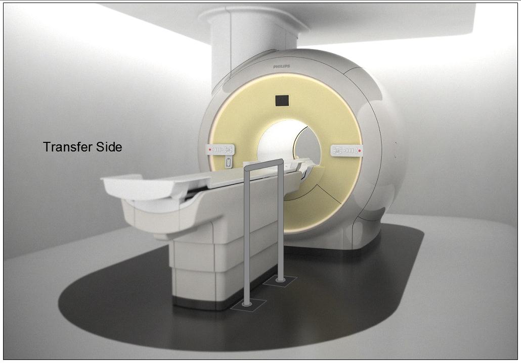
Figure 5.3-10: Illustration of a concept (not to scale) for a detachable floor mounted support. The support could be made to be both height adjustable and detachable at floor level.
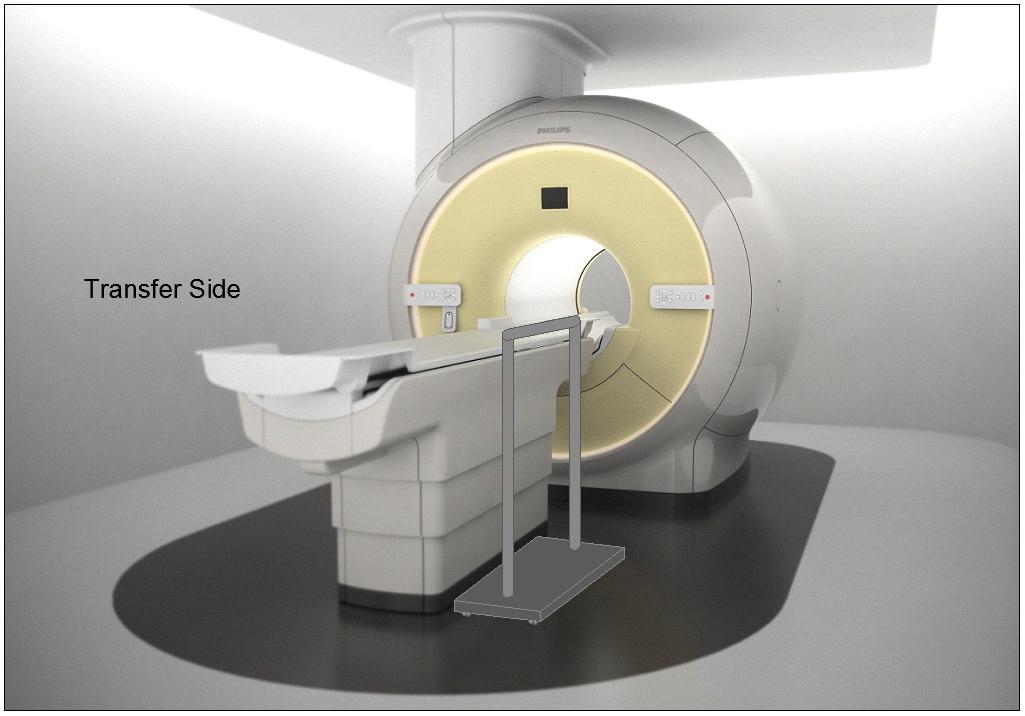
Figure 5.3-11: Illustration of a concept (not to scale) for a wheeled support (wheels would lock and base sufficiently robust and sized for appropriate loadings). The support could be made to be height adjustable.
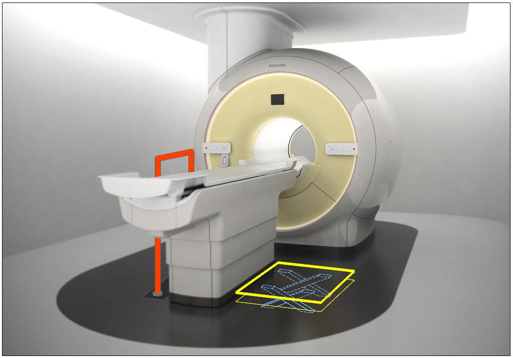
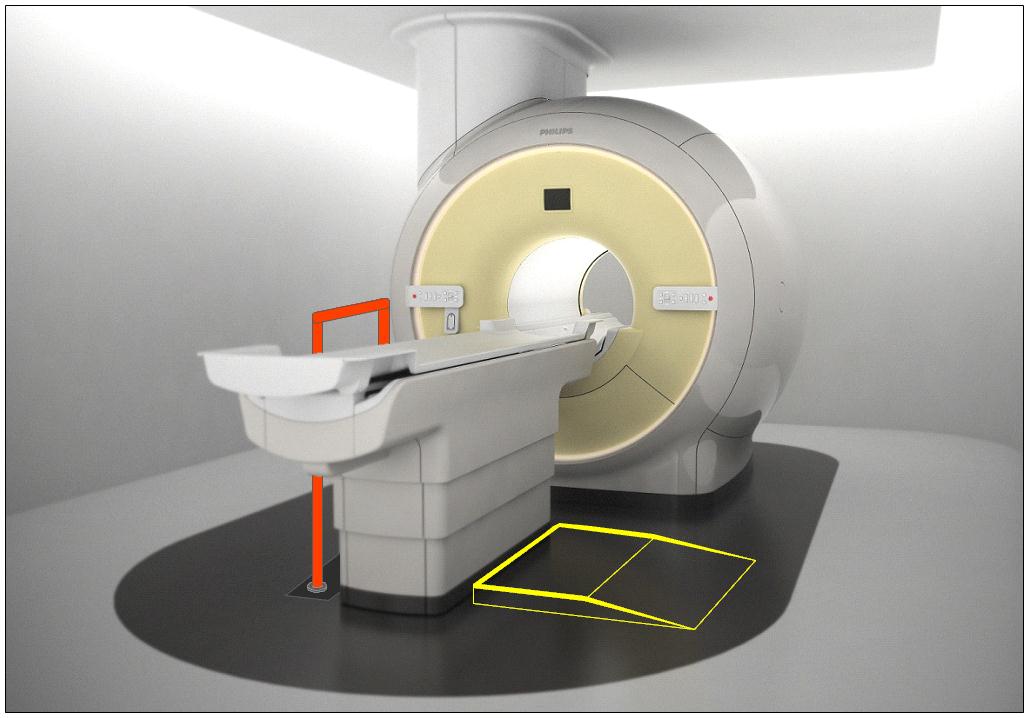
Figure 5.3-12: Illustration of the concept (not to scale) of accessories deployed as part of an accessibility package. The top illustration is shows a floor mounted support combined with scissor lift of Figure 5.3-6. The lower illustration shows the floor mounted support combined with the elevated platform of Figure 5.3-7.
M301.4 Lift Compatibility
Subcommittee Recommendation: (Also agreed to by the full committee.)
An overhead lift (and possibly a gurney-based transfer) may be used in lieu of the provisions for clearances in or around the base of equipment to accommodate the legs of portable floor lifts.
Note: in some circumstances such as in-room MR, the option for a room layout for gurney transfer would be appropriate.
Rationale: The subcommittee recommended the alternate means of using an overhead lift instead of providing clearances for portable lifts because: 1) a ceiling mounted lift can have advantages for better patient transfer and positioning over a portable lift because the portable lift would need to access the diagnostic imaging table from its side or its far foot-end; and 2) table structural design and/or room layout may be such that providing the clearances in and around the base per M301.4.1 and M301.4.2 may be either technically difficult or impractical. Overhead lifts are already currently installed as accessories for some imaging systems.
Overhead lifts are not possible to be used in the MR exam room due to the magnetic fields. Because of this, or for other cases where an overhead lift would be impossible, a gurney-based transfer was considered acceptable provided the gurney met the new standards, even though a double transfer is not ideal.
Below is a picture of an existing CT room with a ceiling mounted overhead lift. Note the degree of flexibility and advantages that this design provides over a portable lift scenario, such as: either side transfer, desired patient orientation prior to transfer, always being available to the patient, no need to manually move the patient by hand, and the ability to move the lift completely out of the way when not needed.
Figure 5.3-13: An existing CT room with a ceiling mounted overhead lift.
6. Transfer Surface Height
6.3 Diagnostic Imaging Equipment
Refer to the Rationale found in Section 5.3 for M301.2.1 and to Section 4.3.
For many types of imaging equipment it will not be feasible to provide a transfer surface meeting the considered minimum height whether it is17, 18, or 19 inches. The same is true for height adjustability for DXA and some X-Ray systems. In those instances an alternate means of access will need to be provided such as the use of auxiliary/ancillary equipment and accessories (“Accessibility Package”).
Given that diagnostic imaging tables are in integral part of the exam and required for accurate results, their design to support very heavy patients, and in some types the existence of imaging components under the table and specialized diagnostic abilities, modifications to the table to go lower and/or be adjustable will always present many design challenges. As such every inch is significant both for designing tables that can go low enough to meet the new standard and in design of accessories or room siting as alternate means to attempt to meet the new standards.
As noted in Section 5.3, the imaging subcommittee did not take a formal position on the transfer surface height. However, during the full committee meeting the manufacturers of diagnostic imaging equipment voted for the “compromise” height of 18 inches.
U.S. Access Board Medical Diagnostic Equipment
Mammography Subcommittee Report:
Final Recommendations on Equipment Criteria
Background: The most frequent type of cancer among women and the second leading cause of cancer-related deaths is breast cancer. A recent study published in the Journal of Women's Health, highlighted that women with disabilities may be less likely to receive a mammogram compared to women without a disability. Prevalence of self-reported mammography use is lower for women with disabilities (72.2% for women 40 years of age or older and 78.1% for women 50 to 74 years of age) than women without a disability (77.8% and 82.6%, respectively), refer to http://www.cdc.gov/features/breastcancerdisabilities/index.html.
Healthcare practitioners find breast-imaging challenging when patients must remain seated in mobility devices such as wheelchairs or scooters for the procedure. In order to obtain a quality image with the needed visualization of the breast tissue, a patient’s ability to approach and position next to the machine is vital. The key equipment barriers arise from the inherent conflict between the mobility device design and the mammography equipment design. The mammography device operation seems designed to require the patient has the ability to stand. Therefore, a woman using a wheelchair will experience two main barriers, the first is that her mobility device cannot get close enough to the mammography machine itself, and secondly, even if she does get close enough to the machine, the breast platform height does not lower enough to image a woman’s breasts while in the seated position.
The Mammography Subcommittee members provided varied expertise. Members included representation from disability advocates, healthcare organizations including technologists, industry designers, and engineers. Industry input provided supporting illustrations, which enhanced the discussion.
Overview: The subcommittee recognized that to get the best accessibility, equipment would need redesign to accommodate persons seated in wheeled mobility devices for the exam. In developing its proposals, the subcommittee considered the physical constraints needed for operation of the equipment, technical feasibility, patient safety, and clinical standards. The subcommittee weighed all the provisions for technical criteria in light of the equipment functionality and the need to image a range of body sizes, functionality, and types.
The subcommittee considered the interaction of mammography devices with individuals using scooter. Due to the need for the woman’s chest wall to be flush with the breast platform, the front scooter components make this position impossible without the person swiveling to the side. Thus, the final recommendations focused on the mammography device’s interaction with wheelchairs. Mammography equipment recommendations are also operable with use of a mammography chair for patients who need to sit for the procedure but do not use a wheelchair.
Mammography imaging involves complex interactions between moving parts. To get the final dimensions, the subcommittee needed to consider the elements “dynamically.” The dynamic angle is necessary because of the way the equipment operates. Recognizing that all operations center on the movable breast platform, recommendations define each component in relationship to the breast platform. The unique aspects of mammography device design and operation requires components to work when the breast platform is at breast height. Since breast platform design affects most of the other device components, defining each in relationship to the breast platform creates proportions that when incorporated into the design process assure that women in mobility devices can get effective imaging.
Ordinarily, the accessibility dimensions are static and measured from a static element such as the floor. Because of the movable breast platform and C-arm, each recommendation defines the other device components in relation to the breast platform. The static point is with the breast platform at the height of 34 inches. This allowed the subcommittee with industry input to consider and maximize the dimensions that improved the accessibility during the equipment’s operation. The result is that this report defines traditional accessibility elements from a different vantage point.
To determine the final criteria for the mammography devices, the subcommittee balanced the knowledge of disability, range of physical characteristics and diversity of body types and sizes with each device component. The members considered industry input on how the dimensions and operation of one element would interact with the other elements. Such input helped interpret how these interactions would affect each other. The subcommittee used the best data available recognizing that the data available did not always match precisely the operations of mammography equipment.
To determine the recommendation, it was critical for all to have an understanding of the equipment components. The diagram below illustrates the set of terminology and the location on a mammography device used to describing the mammography components below. (Figure 1 below)
Figure 1. Overview of the subcomponents of a mammography machine.
In order to get a quality image, the patient’s breast needs to rest on top of the breast platform and the chest wall needs to be flush with the front edge of the breast platform. For this to be possible, the breast platform needs to go low enough to accommodate a patient seated in a wheelchair. There also needs to be enough knee and toe clearance to ensure that the patient can get close enough to the breast platform without knees or feet hitting parts of the equipment. One important feature of mammography equipment is the base support, also shown in Figure 1, which is critical for structural support, seismic stability, and installation safety. This base support must be low enough so that a patient’s footrests can ride over it and it must allow enough unobstructed floor space to ensure that a wheelchair’s front caster wheels do not hit it. Lastly, the configuration of the positioning supports must provide enough flexibility for all patients to be able to reach and hold them. An illustration of each is in Figure 2 below.
Figure 2. Overview of the critical dimensions that impact the accessibility of mammography equipment.
Breast Platform [M303.4.1]
Recommendation: The final recommendation for the minimum height of the breast platform is 26 inches from the floor to the top of the breast platform. The upper height range for the breast platform was not controversial and remained as proposed except for the designation of this as a minimum upper height. The final version of the criteria must clarify that there is no need to limit the height of the breast platform since most are already above the 42-inch measurement at the top end.
Rationale: The subcommittee expressed conflicting perspectives on the minimum breast platform height with members either choosing to support the 26-inch or 28-inch minimum. While all other subcommittee decisions were by group consensus, the group required a formal vote on this issue. Although the subcommittee vote was for 28 inches, during the final public meeting, the full committee supported the 26-inch minimum by a strong majority.
According to industry, equipment currently manufactured ranges anywhere between 25 and 28 inches for the lowest measurement of the breast platform. There were various reasons cited for each of the positions. Recommendations from accessibility experts who developed mammography protocols for women with disabilities identified a need for a breast platform height of 24 inches. Because this recommendation evolved from technologist experience on equipment with less knee space, disability advocates supported the rationale for 26 inches as the minimum. One member cited the diversity of body types and sizes for persons with disabilities as the rationale for the 26 inches. Another member emphasized the importance of considering patients of short stature in addition to considering patients seated in a wheelchair.
Many industry organizations supported the 28-inch minimum. Reasons cited included providing more flexibility for manufacturers and concern that the lower minimum could result in more leg injuries as the technologist lowered the breast platform so close to the lap of the patient using a wheelchair. Informal input from some technologists indicated no problems with imaging patients with disabilities at 28-inch minimum heights. Members disagreed with limiting the height as the method of minimizing the risk of injury since this could happen at any height depending upon the height of the knees of the person.
One member expressed support for the lower height in order to facilitate the Magnified Cranio Caudal (hereinafter “Mag”) view for person needing magnified views of tissue. Mag views require the breast to be located at a specific position in between the x-ray tube and the breast platform. To capture this view, providers place an accessory, often called a “Mag Stand”, on the breast platform, as shown in Figure 3 below. The provider will then position the patient’s breast on top of the mag stand so that the breast is at the correct position between the x-ray tube and the breast platform. The height of the mag stand can vary between 6” and 10”, depending on the characteristics of the x-ray beam and the degree of magnification desired. Since the technologist places this accessory on top of the breast platform, it effectively increases the height and thickness of the breast platform. Beginning with a lower breast platform height could help more patients to have access to the mag view. However, the more significant barrier to patients imaged from a seated position is the increased overall size of the platform (from lap to breast) during a mag view, since it would require the patient to have a very tall torso.
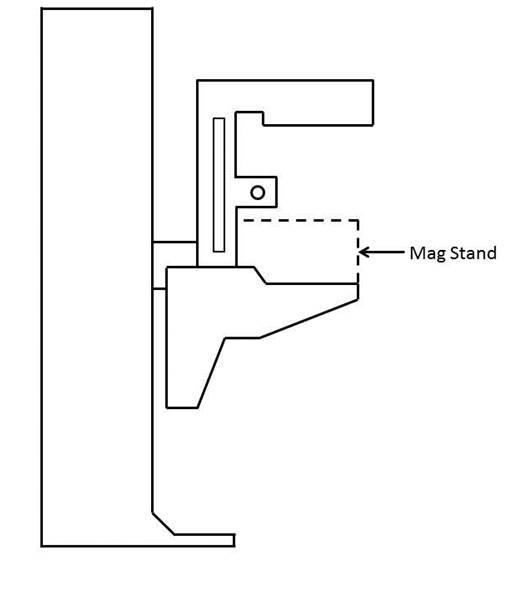
Figure 3. Diagram of a Mag Stand positioning on the breast platform.
Knee & Toe Space [M303.2.4]
Recommendation: The final subcommittee’s recommendations increased the overall knee and toe space to a minimum of 28 inches, from the initially proposed 25-inch absolute dimension. The final recommendation for knee clearance directly underneath the breast platform is a minimum of 18 inches and the final recommendation for the unobstructed floor space in front of the base support is a minimum of 17 inches. Each of these measurements creates a more accessible piece of imaging equipment balanced with the physical attributes and operation of the equipment.
Rationale
The issue of Clearance and Unobstructed Floor Space
The knee and toe clearance dimensions, as well as the unobstructed floor space dimensions, dictate how close a patient in a wheelchair can get to the mammography equipment. The initial NPRM dimensions used information for the clear space under a desk or table as the basis for the proposed regulation. Industry suggested the dimension might be different because mammography procedures require a person’s chest to be flush with the front of the breast platform. The subcommittee reviewed the existing data of wheelchair users1 and industry input on how these elements technically affect one another. Below is an overview of the rationale for each of the final recommended dimensions affecting clearances in front of the gantry. (Table 1)
Table 1. Critical Equipment Dimensions with the relevant Anthropomorphic Data
| Critical Dimension | Anthropomorphic Data /Rationale | Final Decision |
| Height of Breast Platform At Time of Measurement | Set point for assuring knee clearance at 27” above the ground Assures proportionality of each element to each other |
34" |
| Knee Clearance Depth at 27” above the ground | 95th percentile knee clearance measured from abdomen to front of person’s knees, female-only data | 18" minimum |
| Clearance Depth at Toe Height above the ground | 95th percentile knee clearance measured from abdomen to front of person’s legs at toe height above the ground, combined male and female data due to availability | 22" minimum |
| Toe Height | 95th percentile toe height, female-only data; consideration of breast platform moving to lower heights | 16" minimum |
| Overall Knee and Toe Clearance | Abdomen-to-toe depth, female only data; technical information; consideration of positioning methods | 28" minimum |
| Unobstructed Floor Space | Abdomen-to-caster wheel depth, combined male and female; technical information; consideration of positioning methods | 17" minimum |
One issue affecting how close the patient can get to the mammography machine is the base support, an essential equipment element that intrudes into the floor space. As discussed below, the purpose of the base support is to eliminate any instability caused by the weight of the cantilevered c-arm. Moving the c-arm further away from the gantry would increase the overall knee and toe clearance, but would also require an increase in the size of the base support in order to stabilize the equipment. Since the base support obstructs the floor space, resulting gains from increasing the knee and toe clearance are minimized because of the simultaneous increase in the size of the base support. The subcommittee considered this balance when making final decisions about overall knee and toe space and unobstructed floor space.
While discussing these issues, the subcommittee also considered positioning methods for patients using wheelchairs. During a mammography procedure, the patient’s chest is flush with the front edge of the breast platform and the technician positions the patient’s breast on the breast platform. In order to image as much of the breast as possible, patients cannot be seated in the “natural” sitting position. They will need to sit up straight in order to situate as much breast tissue as possible on the breast platform. For patients seated in a wheelchair, a common positioning technique is to place towels, pillows, or other positioning aids behind the patient’s back in order to sustain an upright pose during imaging. This upright pose is necessary regardless of how close the patient can naturally get to the breast platform. The pose reduces the abdomen-to-toe and abdomen-to-caster edge dimensions by a couple inches. The anthropomorphic data shows that 30.5 inches and 19.5 inches are the needed overall knee and toe clearance and unobstructed floor space dimensions, respectively. (Data shown below in Tables 2 and 3).
Table 2. Abdomen Depth Data to determine overall knee and toe clearance
| Percentile Value | |||||
| User Group | Median – 50th | 75th | 90th | 95th | Max |
| Female Manual Wheelchair Users (n=130) | 23.2 | 26.4 | 29.2 | 30.6 | 33.0 |
| Female Power Wheelchair Users (n=89) | 21.6 | 24.8 | 28.1 | 30.4 | 36.7 |
Table 3. Abdomen-Caster Edge Depth
| Percentile Value | |||||||
| User Group | Min | 5th | 10th | 50th | 90th | 95th | Max |
| Manual Wheelchair Users (n=101) | 2.0 | 5.6 | 6.8 | 11.4 | 17.1 | 18.5 | 20.3 |
| Power Wheelchair Users (n=67) | 4.1 | 6.0 | 7.8 | 10.9 | 17.6 | 19.3 | 21.9 |
In applying the various positioning considerations along with the data, measurements of 28 inches (full knee and toe clearance above the base support) and 17 inches (clearance underneath the breast platform) would capture nearly everyone. Looking purely at the anthropomorphic data above, these dimensions accommodate ~90% of the population. In adjusting for the needed upright pose, an adjustment of at least 2.5 inches is likely. If so, the equipment accommodates 95% of the population since the difference is ~2.5 inches less than the 95th percentile of the corresponding anthropomorphic dimensions. Members recognized that these dimensions are an optimal blend of accessibility and technical feasibility2 when balanced with the physical design and operation of the equipment,
Figure 4. Overview of the critical dimensions that define the knee and toe space underneath the breast platform.
Relationship of knee and toe space with breast platform
The shape of the breast platform affects the shape of the knee and toe space. Since the shape of the breast platform varies across different manufacturers and equipment, merely defining the knee clearance as the “knee clearance below the breast platform” would lose the interrelated aspect of these elements. This means a particular feature on the breast platform does not define the required location of the knee clearance. Instead, the knee space dimension is located with the platform at a specified height. By defining the height of the breast platform as the “set point” for the other dimensions, all clearances have a static measurement point that assures maximum clearances during operation of the equipment. Ultimately, the knee dimensions must be determined when the person’s breasts are on top of the breast platform and there must be sufficient clearance at the height of the person’s knees, as is shown in Figure 6 below. By using this approach, the subcommittee was able to maximize the clearances in relationship to the equipment operations.3
The NPRM proposed measuring the knee clearance under the breast platform at 27 inches above the ground. Industry used this dimension and determined the proportionate height of the breast platform at a height of 34 inches. The subcommittee agreed to this as a “set point” (Identified as “Breast Platform Height” in Figure 5 below). Thus, when the patient’s breast is on the breast platform, there must be sufficient knee clearance at 27 inches above the ground (“Knee Height” in Figure 5 below). These dimensions (27 and 34-inch heights) are the same as is defined by the current ADA/ABA accessibility standard to accommodate wheelchair users at desks. The dotted lines in Figure 6 below illustrates this dimension.
Figure 5. Using the height of the top of the breast platform as a set point for the knee and toe clearance measurements.
Figure 6. Illustration of current ADA/ABA standard to accommodate wheelchair users sitting at desks.
The two dimensions define the breast platform requirements for a person with the deep knees and a tall wheelchair. When the breast platform lowers to accommodate shorter patients in wheelchairs, there will be ample knee clearance for those patients. Conversely, as the breast platform moves up for patients who have longer torsos, the breast platform will just be moving away from their knees and legs, thus giving them ample space as well.
Toe Height
The NPRM defined the toe clearance at a height of 9 inches. However, as the breast platform moves up and down, it may intrude on the toe space. The subcommittee recommended that the toe height be set to 16 inches. Looking further at female-specific toe height data, the 95th percentile toe height was 13 inches for manual wheelchair users and 16.1 inches for power wheelchair users. As such, the subcommittee recommended that the toe height be set to 16 inches (when the breast platform is at the 34 inch height discussed above). This higher 16-inch measurement (compared to the originally proposed 9-inch toe height) would also minimize the chance of the breast platform hitting patients’ toes when the breast platform moves to some of its lower heights
Again, normally a toe space dimension defines a static unobstructed space. In this case, in order to get the maximum accessibility out of all the dimensions, the final recommendation requires the dimension of toe clearance is determined at the 34-inch breast platform height (see discussion above). This higher 16 inches measurement (compared to the originally proposed 9 inches toe height) would minimize the chance of the breast platform hitting patients’ toes when the breast platform moves to some of its lower heights. Providing this dimension helps define the outer limits of the breast platform configuration in a way that maximizes the dimensions for accessibility.
When considering toe height, it is more convenient to use the anthropomorphic model that defines toe height specifically, shown below in Figure 7 for manual chairs.
Figure 7. Anthropomorphic model used to analyze toe height.
If the toe height is at 16 inches above the ground when the breast platform is at 34 inches above the ground, we are accommodating the 90-95th percentile person. The toe height is more than enough to accommodate wheelchair users since the 95th percentile toe height is 13 inches. When the breast platform lowers to a 26-inch height, then the toe clearance height would be 8 inches. This maintains proportions likely to accommodate persons needing the breast platform at the lowest height since knee height is also less.
As discussed above, the minimum range of travel for the breast platform is 26 inches to 42 inches. When the top of the breast platform is at its lowest position of 26 inches, there is no need for knee clearance at 27 inches above the ground (knees will be lower than breast height). Defining knee and toe clearances based the lowest height breast platform at 26 inches may compromise taller patients in higher wheelchairs. As such, it is more appropriate to measure the dimensions of the knee and toe space set the breast platform to a higher height to ensure that the greatest required knee and toe clearances. Then, when the breast platform lowers to accommodate smaller patients, there will be more than enough clearance available.
The diagram below illustrates the final knee and toe clearance recommendations (Figure 8).
Figure 8. Summary of knee and toe clearance recommendations.
Notes:
1. Where possible, the subcommittee focused only on the anthropomorphic data of women, the primary group needing mammography.
2. The concept of technical feasibility is one found in other areas of access. It recognizes that there may be physical factors that make create limits to what functions can be achieved even with redesign. In mammography, the physical stability and operation of the equipment fall into this category. The committee recognizes that future visionaries may be able to “re-vision” new devices.
3. Given the differing shapes of mammography devices, defining the dimensions in relationship to each other with a static measurement point for the breast platform assures accessibility despite the varied shapes and dimensions of the breast platform. Otherwise,, it is quite possible to configure a piece of equipment that meets all the clearances yet does not provide accessibility if there is not a defined method of measuring the clearances in relationship to the breast platform.
4. Measured from the point on the floor where a perpendicular line intersects the front edge of breast platform shown in Figure 10.
Base Support [No specific provision—affects M303.2.4]
Recommendation: The final proposal on the base support is for 1½ inch high maximum base support with additional sloping permitted at 25 inches or beyond4 to the gantry if needed for additional structural support.
Rationale
The base support is of fundamental importance to mammography equipment and provides structural support, seismic stability, and installation safety. It does obstruct the floor space in front of the gantry and, thus, may limit how close a wheelchair can get to the equipment. To respond to this issue, industry proposed a configuration that would allow wheelchair footrests to ride over it so it causes minimal obstruction to the floor space in front of the gantry. To discuss the maximum base support height, the sub-committee looked at anthropomorphic data regarding footrest heights. The footrest height data measures the height from the floor to the top surface of the footrest at its proximal outside corner. To determine the necessary clearance for the footrests, the subcommittee used the calculated thickness of the footrests (~0.5 inch) minus the footrest height measurement. The ~0.5” thickness is the recommendation from the data supplied by Steinfeld and D’Souza. The anthropomorphic data, as well as the calculated footrest clearances, are below in Tables 4 and 5.
Table 4. Anthropomorphic data on measured footrest heights
| Device Type | Min | 5% | 10% | 50% | 90% | 95% | Max |
| Manual (n=101) | 1.2 | 1.7 | 2.2 | 4.1 | 7.2 | 10.0 | 36.2 |
| Power (n=67) | 1.8 | 2.7 | 3.1 | 4.8 | 8.8 | 10.5 | 16.9 |
Table 5. Actual footrest height clearances
| Device Type | Min | 5% | 10% | 50% | 90% | 95% | Max |
| Manual (n=101) | 0.7 | 1.2 | 1.7 | 3.6 | 6.7 | 9.5 | 35.7 |
| Power (n=67) | 1.3 | 2.2 | 2.6 | 4.3 | 8.3 | 10 | 16.4 |
A maximum base support height of 1.5 inches will provide room for the structural components necessary for an effective base support design and will also be accessible by ~92% of manual chair users and over 95% of power chair users.
The subcommittee also discussed adding an allowance for a sloped region at the base of the gantry. Many of the mammography machines today also have important informational displays at the base of the gantry, on top of the base support (shown as the checkered region in Figure 9 below) that display information such as compression force and compression thickness.
Industry input on these displays cited customer feedback. The technologists felt that while positioning the patient’s breast, they were naturally looking downward, and by having the display at the base of the gantry, they could watch the compression force and breast thickness readout while positioning the patient. They suggested this location for the display as a method for improving workflow. On other machines, this region has other mechanical and electrical components that are important to the function of the equipment.
At the full committee meeting, there was extensive discussion regarding the additional sloped region. Several members felt strongly that the additional sloped region must be justified by structural stability since displays could be located elsewhere. Members commented that not all equipment has displays in this region, so it seemed possible for industry to redesign the displays to create less interference.
The subcommittee agreed on adding an allowance for a sloped region as defined by Figure 10 below. Figure 11 below illustrates this region overlaid with the anthropomorphic data.
Figure 9. Location of the display area at the base of many mammography machines.
Figure 10. Summary of base support recommendations.
Figure 11. Base support configuration in red shown over the anthropomorphic data.
Steinfeld and D’Souza supplied this chart plotting their study’s findings on the depth of participant’s footrests. The black lines show the areas with no interference between the footrests and base support interface. The black lines illustrate areas where no footrests would intrude. However, based on the technical feasibility and clinical use considerations discussed in the above sections, industry provided the overlay configuration in red. The base support configuration illustrated above is the final recommendation.
The green dots in the above scatter plot illustration represent observed values for footrest height, (on the vertical axis) and footrest depth (on the horizontal axis) measured for manual wheelchair users to the abdomen point. The footrest clearances (calculated in Table 5 above) are ~0.5” lower than the footrest heights defined here. The footrest depth is the horizontal distance from the abdomen to the distal (forward-most) edge of the footrest. The subcommittee used the data for manual chairs because manual chairs are lower than the power chairs.
Summary Figure: Figure 12 shows the final recommended component dimensions in one diagram.
Figure 12. Summary of final clearance recommendations, to be measured when the top of the breast platform is at 34”.
Notes:
4. Measured from the point on the floor where a perpendicular line intersects the front edge of breast platform shown in Figure 10.
Standing Supports [M305.2]
Recommendation: The final recommendation of the subcommittee is to remove the requirement for standing supports in reference to mammography equipment. Instead, positioning supports should be required. To be useful, positioning supports must shaped for grasping, positioned within the reach range of all users, and be 12 inches long minimum when located on the moving c-arm or 18 inches long minimum when in a fixed location.
Rationale
The original criteria proposed in the NPRM included vertical standing supports on both sides of the equipment that were 18 inches in length. During discussion, there was general agreement that the real use of these supports is for positioning, and thus, not meant to support the full weight of the patient or to keep a patient in a standing position during the exam. Industry representatives posited that if a patient has limitations or balance issues severe enough to need standing assistance, then the healthcare provider should position her in a seated position for safe imaging. The primary use of these supports is for positioning of the arms during the imaging process to keep them out of the field of view of the image. For these purposes, the equipment criteria should designate these supports as positioning supports and be designed with the structural strength required for positioning activities.
Furthermore, since many types of mammography equipment mount the supports on the c-arm, they will move up and down with the breast platform. In these cases, they do not need to be as long as 18 inches to provide sufficient flexibility for patients to reach them. Industry representatives also indicated that there are controls in the area where these positioning supports are located. It is important that the patients’ hands do not accidentally hit these controls when they are holding the positioning supports. For this reason, industry will sometimes intentionally shorten the length of these handholds to less than the 18-inch proposal. Considering these factors, the full committee agreed that a 12-inch long positioning support would be sufficient if it moved with the movable breast platform.
Mammography Chair [M302]
Recommendation: The mammography chair is an essential piece of equipment allowing persons who are unable to stand or balance to sit for the diagnostic procedure. The chair must meet the elements of M302 with the additional requirement that any footrests must accommodate and ride over the base support.
References:
The following sources were referenced for the anthropomorphic data presented here. Specific citations are made in the full committee report.
IDeA Center Study at the University of Buffalo, New York: Summary analysis of wheelbase measurements on wheeled mobility devices.
IDeA Center at the University of Buffalo, New York: The Wheeled Mobility Anthropometry Project, Final Report, pages 89-92.
D’Souza, et al. “Clearance Space Envelopes of Wheeled Mobility Device Users for Computer Workstations”. Proceedings of the Human Factors and Ergonomics Society Annual Meeting 2012.
D’Souza, Steinfeld. “Revised Knee Clearance Depth and Footrest Clearance dimensions for sizing of mammography equipment.” Memorandum. April 23, 2013.
Notes:
1. Where possible, the subcommittee focused only on the anthropomorphic data of women, the primary group needing mammography.
2. The concept of technical feasibility is one found in other areas of access. It recognizes that there may be physical factors that make create limits to what functions can be achieved even with redesign. In mammography, the physical stability and operation of the equipment fall into this category. The committee recognizes that future visionaries may be able to “re-vision” new devices.
3. Given the differing shapes of mammography devices, defining the dimensions in relationship to each other with a static measurement point for the breast platform assures accessibility despite the varied shapes and dimensions of the breast platform. Otherwise,, it is quite possible to configure a piece of equipment that meets all the clearances yet does not provide accessibility if there is not a defined method of measuring the clearances in relationship to the breast platform.
4. Measured from the point on the floor where a perpendicular line intersects the front edge of breast platform shown in Figure 10.
Medical Diagnostic Equipment Accessibility Standards
Sub Committee Recommendations
Stretcher Final Report
May 31, 2013
The Subcommittee’s technical recommendations for the stretchers have taken into consideration the following technical criteria proposed in Chapter 3, part 1195 to Title 36 of the Code of Federal Regulations. Specifically, Section M301, Diagnostic Equipment Used by Patients in Supine, Prone, or Side-Lying Position.
Equipment Evaluated: Stretchers
Stretchers are typical equipment used in healthcare settings for patients in supine, prone, or side-lying positions.
Chart from Proposed Accessibility Standards for Medical Diagnostics Equipment Appendix to part 1195
| Patient Positions Equipment Designed to Support | Equipment Features Addressed in Technical Criteria | Types Of Equipment To Which Technical Criteria Applies |
| Supine, prone, or side-lying position (M301) | Transfer surface, including height, size, and transfer sides Transfer supports, stirrups, and head and back support Lift compatibility |
Stretchers |
| Seated Position (M302) | Transfer surface, including height, size, and transfer sides Transfer supports, stirrups, and head and back support Lift compatibility |
Stretcher chairs |
Equipment Evaluated: Stretchers
Sub-Committee Summary of Scope for Recommendations
The Full Committee and Sub-Committee are both in agreement that Beds are excluded from these proposed standards as beds are used for therapeutic and not diagnostic procedures. Stretchers are used not only as transport devices but are heavily used in the healthcare setting to perform diagnosis.
M301.2.1, M302.2.1 Transfer Height
Proposed requirement:
The height of the transfer surface during patient transfer shall be 17 inches (430 mm) minimum and 19 inches (485 mm) maximum measured from the floor to the top of the transfer surface.
• Sub-Committee Recommendation: 17 inches with exceptions.
Exception: During patient transfer, the height of the transfer surface shall have a lower height of 21" maximum and adjustable to a higher height of 25" minimum, measured from the floor to the uncompressed height of the patient support surface.
Rationale: Early studies are showing that achieving a low height for stretchers in the 17"-19" range to be very difficult due to the various roles of stretchers being not only diagnostic pieces of equipment, but as that they are used for transport. The very nature of the mobility systems and components of the stretcher configuration, including wheels, brakes and steering systems as well as their ability to carry portable equipment such as IV's, infusion pumps, monitors, oxygen, foley catheter bags, etc. all of which create serious packaging constraints that limit the low height of the patient support surface.
Patients may utilize stretchers for long periods of time – e.g. emergency room (primary equipment used) or while waiting to have their diagnostic tests performed. Stretchers are also widely used in outpatient surgery centers. Other considerations for stretchers are the surfaces (mattress) that is purchased separate from the stretcher deck. The Standard of Care for healthcare organizations is to have a pressure-relieving surface on the stretcher to help prevent pressure ulcers. These surfaces may range between 4” to 5” in thickness - this will add to the vertical height of a stretcher when measuring from the floor to the top of the surface (uncompressed). The Committee acknowledges this Standard of Care and feels it is important to maintain when measuring overall the height. Stretchers currently have a low deck of 20” – 23”.
This is also coupled with the complication of a 6" tall lift clearance window that forces foot operated controls up. These elements are all competing for the same vertical space and it will take full development of the stretcher to confirm or deny the ability to meet the desired range of 17"-19". Until that time, it is proposed we take a more conservative position and push the low height slightly higher for stretchers until the technology can catch up with the regulations and full feasibility studies can be researched. The recommendation for exception is 21" (with a oxygen holder). When access is unachievable, a portable floor or ceiling lift shall be utilized.
Figure 1: Stretcher Vertical Height Constraints – Configuration of Features
(Picture provided by Hill-Rom)
Note: In the healthcare setting having a single stretcher type that services a majority of patient conditions is desired. Patients may use stretchers for transport only, however many patients may also require supporting oxygen during transport to and from diagnostic procedures.
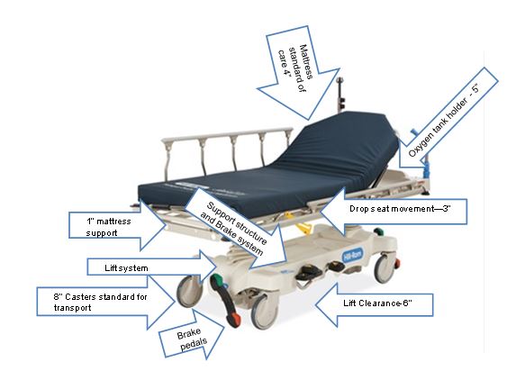
Figure 2: View of Stretcher with Oxygen Tank
Note: Oxygen tanks require a minimum of 5” of vertical height in stretcher configuration
(Picture provided by Stryker)
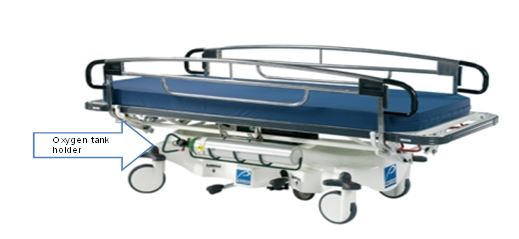
M301.2.2, M302.2.2 Transfer Size
Proposed requirement:
30" wide minimum and 15" deep minimum
• Sub-Committee Recommendation:
28" wide minimum and 17" deep minimum. This transfer surface is located on the longitudinal (long) side of the stretcher—either right or left side
Rationale: Based upon full committee discussion and harmonization with Exam Table Subcommittee.
M301.2.3 Transfer Sides
Proposed requirement:
The transfer surface shall be located to provide options to transfer from a mobility device onto one short side (depth) and one long side (width) of the surface.
• Sub-Committee Recommendation:
The transfer surface shall be located to provide options to transfer from a mobility device onto both long sides (length), right and left, of the surface.
Rationale: Revision is based upon the configuration and use of stretchers. The configuration of stretchers will not allow for unobstructed access to a transfer surface located at either the foot end or head. The location of the Transfer Side will be located on the patient right or patient left at roughly midway between the foot end and head end. This places the position at a desirable location along the length of the stretcher side so as when the transfer is completed, the patient is in the correct location relative to the articulation of the backrest. As a result, a patient can only access one long side of the transfer surface, the one short side will be inaccessible.
Proposed requirement:
Each transfer side shall provide unobstructed access to the transfer surface.
• Sub-Committee Recommendation:
Each transfer side shall minimize obstructions to the transfer surface. Obstructions shall not be vertically less than 1" (25 mm) nor be horizontally more than 3" (75 mm) from the edge of the patient support surface provide unobstructed access to the transfer surface.
Rationale: The position of obstructions has been discussed by the full committee and the Exam Table subcommittee and has established an obstruction protruding no more than 3" beyond the edge of the transfer surface.
It is proposed herein that an additional requirement be added to restrict how high the obstruction can exist in comparison to the top of the transfer surface. Guidance from IEC 60601-2-52 does establish the maximum vertical obstruction of being not less than 1" below the top of the transfer surface.
M301.3 Transfer Supports
Proposed requirement:
Transfer supports shall be provided for use with the transfer sides required by M301.2.3 and shall comply with M305.2.
• Sub-Committee Recommendation:
No revision.
* Other Transfer Support Dimensions: (*not included in the Proposed Rule)
• Sub-committee Recommendation:
Length - At least 15 inches (300 mm) in length and located on the length of the transfer surface. Located on the opposite side of the access point.
Circular cross sections – Circular cross sections must have an outside diameter of 1¼ inches minimum and 2 inches maximum. Section may be discontinuous (see Rationale) along the length of the Gripping Surface not exceeding 20% of the length of the gripping surface.
o Rationale: Discontinuous allows for the vertical support structure that is necessary for supporting the grip.
Non-circular cross sections - Non-circular cross sections must have a cross section dimension of 2 inches maximum and a perimeter dimension of 4 inches minimum and 4.8 inches maximum. Section may be discontinuous* along the length of the Gripping Surface not exceeding 20% of the length of the gripping surface.
Transfer Supports Position
• Sub-Committee Recommendation:
Located longitudinally within the long side of the of the transfer surface. Transfer support will be located on the opposite side of the transfer side.
Length: Minimum of 15" of continuous support.
o Rationale: This is to accommodate the articulation that is necessary for the head and back support on stretchers.
Height: Located no less than 6 inches (150 mm) and no more than 19 inches (482 mm) above the patient support surface
Horizontal Distance from Transfer Surface: No more than 3 inches (75 mm) from the edge of the patient support surface.
o Rationale: Currently, and it is envisioned that transfer supports will continue to be enabled through the side rail systems currently employed on stretchers. Based on the nature of side rail mechanisms to allow them to fold and store properly. Currently, the state of the art for side rail have them placed just under 3" outboard of the mattress surface edge (transfer surface edge). Therefore, it is requested that this horizontal dimension allow for current designs to fall under the proposed rule.
Figure 3: Transfer Support Location – Plan View
(Drawings designef for Access Board by Stryker)
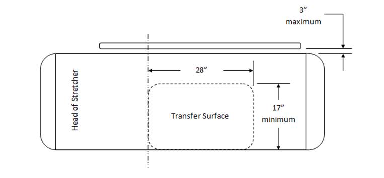
Figure 4: Transfer Support Location – Side View
(Drawings designef for Access Board by Stryker)
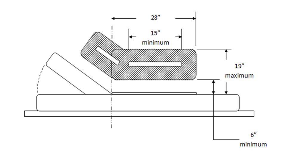
M301.3.2 Stirrups
Proposed requirement:
Where stirrups are provided, they shall provide a method of supporting, positioning, and securing the patient’s legs.
• Sub-committee recommendation:
Where stirrups are provided, a method shall be provided for supporting, positioning, and securing the patient’s legs.
Rationale: Stirrups (also called foot supports) alone may not provide a method of supporting, positioning, and securing the patients legs, but may be supplemented by or used in conjunction with a secondary accessory that provides this function. Typical accessory is a set of calf supports that support the patient legs just below the knee. Recommending a slight revision to this wording. When stirrups are provided "A" method shall be provided for supporting, positioning and securing the patient's legs. This wording change allows for alternate methods to be used for this repositioning, etc Full Sub-committee approval for this change.
M301.3.3 Head and Back Support
Proposed requirement:
Where diagnostic equipment used by patients in a supine, prone, or side-lying position, and diagnostic equipment used by patients in a seated position can be adjusted to reclined positions (M301.3.3 and M302.3.3) would require head and back support to be provided throughout the entire range of the incline. This is consistent with ANSI/AAMI HE 75 which recommends that the “support surface needs to be adjustable or have adjustable features (e.g., for the head, neck, back, lumbar region, leg, knees, and foot, as appropriate) to support patients in various postures and body positions in a manner that optimizes their comfort. See ANSI/AAMI HE 75, section 16.4.7 (h. Although not required by the proposed standards, examination tables that can be adjusted to a sitting position and then reclined to a horizontal position may be easier for patients with disabilities to transfer onto and off of than examination tables that are horizontal only.
• Sub-Committee Recommendation:
No revision.
M301.4 Lift Compatibility
M01.4.1 Clearance in Base
Proposed requirement:
The base of the equipment shall provide a clearance 44 inches (1120 mm) wide minimum, 6 inches (150 mm) high minimum measured from the floor, and 36 inches (915 mm) deep minimum measured from the edge of the examination surface. Where the width of the examination surface is less than 36 inches (915 mm), the clearance depth shall extend the full width of the equipment. Equipment components are permitted to be located within 8 inches (205 mm) maximum of the centerline of the clearance width.
• Sub-Committee Recommendation:
The base of the equipment shall provide a clearance 39 inches (1000 mm) wide minimum, 6 inches (150 mm) high minimum measured from the floor, and 36 inches (915 mm) deep minimum measured from the edge of the examination surface. Where the width of the examination surface is less than 36 inches (915 mm), the clearance depth shall extend the full width of the equipment. Equipment components are permitted to be located within 8 inches (205 mm) maximum of the centerline of the clearance width.
Rationale: Harmonization with IEC 60601-2-52 "Particular requirements for the basic safety and essential performance of medical beds" Change clearance requirement to:
39 inches (1000 mm) from 44 inches (1120 mm). This is the current International standard for clearance. Recommend that this be harmonious with this standard.
For stretchers with a shorter wheelbase than “standard” size stretcher bases, the clearance for a lift may include a lift window that is a combination of “Clearance in Base” and “Clearance Around Base”. With a short wheelbase, one leg of a floor based mobile patient lift will be placed through the base and the second leg of the lift will be placed around the base. The size of the window should still apply as written, these comments are placed here to identify a difference in how product configuration should not affect the clause.
IEC 60601-2-52 Particular requirements for the basic safety and essential performance of medical beds provides a similar requirement for lift clearance in the base. The dimensions there are 150mm x 1000mm. Recommendation here is to shrink the 1120mm dimension to 1000mm (39”) dimension to harmonize with the international standard.
M302 Diagnostic Equipment Used by patients in Seated Position
• Sub-Committee Recommendation
May be seen as applying to some versions of “Stretcher Chairs” used in Emergency Departments. These include products produced by Stryker, Hausted, Transmotion, etc.
Recommendation is that this section does not include “non-clinical” products (general chairs and/or recliners) used to support patients in a sitting position in “Fast Track”, “Urgent Care” or Triage settings.
It is important to create a distinction in the definition of these products so as to ensure that clinical products such as Examination Chairs and Stretcher Chairs fall under the extent of the rule, but that General Chair Seating or Recliners do not fall under the extent of the rule. Discussion regarding if stretchers fall under this criteria. Stretchers have a head & back support that keep the patient in a semi-reclined position, however the patients legs are not in a dependent position such as that when sitting in a chair. Stretchers are accessed when the stretcher is in a flattened position. Recommend that stretchers not be included in Diagnostic Equipment used by patients in a seated position.
M302.2 Transfer Surface
M302.2.3 Transfer Sides
Proposed requirement:
The transfer surface shall be located to provide options to transfer from a mobility device onto one short side (depth) and one long side (width) of the surface.
• Sub-Committee Recommendation: No revision as a stretcher chair should be the equivalent of a mobile examination chair.
M305.2 Transfer Supports
M305.2.2 Transfer Supports Structural Strength
Proposed requirement:
Transfer supports and their connections shall be capable of resisting vertical and horizontal forces of 250 pounds (1,112 N) applied at all points on the transfer support.
• Sub-Committee Recommendation:
Transfer supports and their connections shall be capable of resisting vertical and horizontal forces of 250 pounds (1,112 N) applied at the worst case accessible location without creating an unacceptable risk.
Rationale: Manufacturer shall determine the worst case accessible location(s) and test at these locations.
Acceptance criteria must be defined. It is understood that the Transfer Support will deform to some degree under these loads. This clause should limit elastic deformation and prohibit permanent deformation or breakage.
Possible language as modified from IEC 60601-2-52: “Transfer Supports shall be designed to withstand the forces applied during reasonably foreseeable use without creating an unacceptable RISK.”
As manufactures of medical equipment, ISO 14971 “Application of risk management to medical devices” is a commonly adhered to standard. As a result, product development normally includes the application of risk management practices and will consequently define “unacceptable risk” as it applies here.
M305.2.3 Fittings
Proposed requirement:
Transfer supports shall not rotate within their fittings
• Sub-Committee Recommendation:
Transfer supports shall not rotate within their fittings, when in the use or latched position, to the point of creating an unacceptable risk when subjected to the load conditions as prescribed in M305.2.2.
Rationale: It is understood that transfer supports will be of varying configuration and designs. Some may be removable, some foldable or articulating. In these cases, it may be advantageous to allow them to rotate, translate, fold, etc. but they should not do so at loads below those prescribed in M305.2.2.
References
IEC 60601-2-52 "Particular requirements for the basic safety and essential performance of medical beds"
ANSI/AAMI HE 75, section 16.4.7 (h.
Medical Diagnostic Equipment Accessibility Standards
Sub-Committee Recommendations
Weight Scales - Final Report
May 31, 2013
The Subcommittee’s technical recommendations for the weight scales have taken into consideration the following technical criteria proposed in Chapter 3, part 1195 to Title 36 of the Code of Federal Regulations. Specifically, section M303, patient positions equipment designed to support seated in a wheelchair.
Abbreviated Chart from Proposed Accessibility Standards for Medical Diagnostics Equipment Appendix to part 1195, Section M303.
| Patient Positions Equipment Designed to Support | Equipment Features Addressed in Technical Criteria | Types Of Equipment To Which Technical Criteria Applies |
| Seated in a wheelchair (M303) | Wheelchair space, including orientation, width, depth, knee and toe clearance, and surface slope Changes in level at entry to wheelchair space, including ramps Components capable of examining body parts of patients seated in a wheelchair, including height of breast platforms |
Imaging equipment designed for wheelchair use Weight scales designed for wheelchair use |
| Both seated in a wheelchair (M303) and in a standing position (M304) | Standing supports | Weight scales designed for both patients using wheelchairs and those standing |
Equipment Evaluated: Wheelchair weight scales with single ramps, dual ramps, stand-on scales and stow-a-weigh scales.
Types of Scales
| Single Ramp Scale (Diagram provided by US Access Board) |
Dual Ramp Scale (Picture provided by Scale –Tronix) |
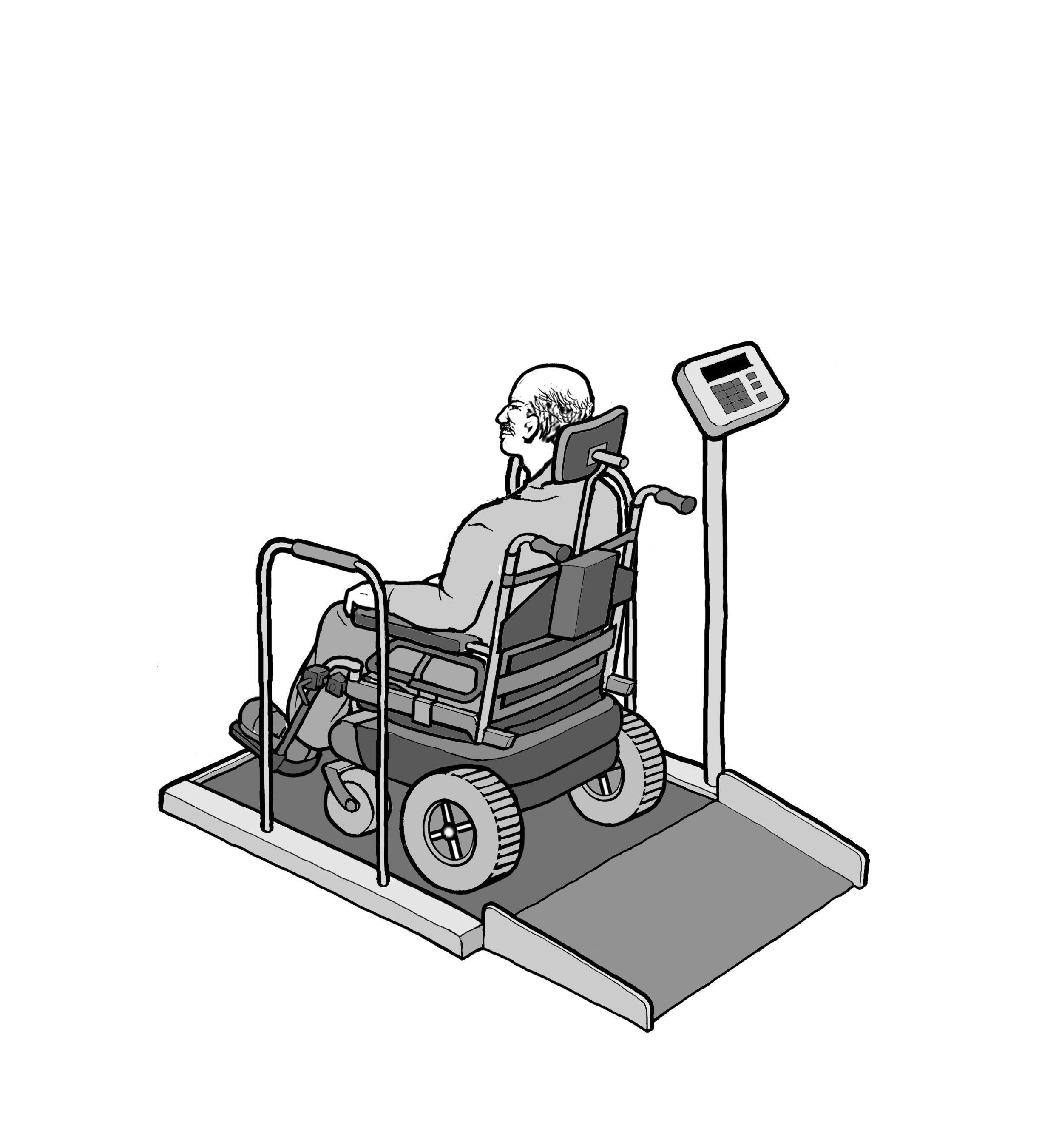 |
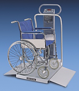 |
| Portable Scales (Picture provided by Scale -Tronix) |
Wall Mounted or “Stow-A-Weigh” (Picture provided by Scale – Tronix) |
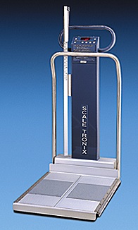 |
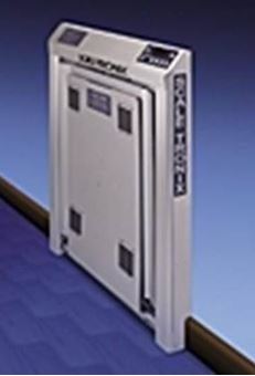 |
Sub-Committee Summary of Scope for Recommendations
Though sometimes avoided, all patients should have their weight taken as it is a basic screening measurement. It is sometimes difficult to take the weight of patients who have mobility or stability issues or for those who use wheeled mobility devices. However, without an accurate and current weight measurement, chances of missing diagnosis or incorrectly prescribing medications increase.
The goal of the sub-committee is to encompass the broadest range of individuals with mobility disabilities including wheeled mobility device users in the following recommendations. All standard size manual wheelchairs, powered wheelchairs, small to mid-range scooters and most bariatric size, extra wide manual chairs can be accommodated as it relates to the platform size recommendations; however, some of the larger roadside scooter models, typically a 4-wheeled base scooter, may not be accommodate by this platform size.
Rationale for including scooters in equipment evaluation: Scooter use is increasing as aging ‘Baby Boomers’ acquire mobility disabilities, etc. In 1994-95, 0.21% of elderly (65+) adults used scooters (64,000 people), according to our analysis of the NHIS-D published in 2000 in "Mobility Device Use in the United States." In 2011, 2.3% of elderly population 65+adults use scooters (about 800,000 people), according to data from the National Health and Aging Trends Study. Trend is more than 10 times as many people in 16 years use scooters.
Compare that to wheelchair usage among the 65+ elderly: 2.9% (900,000 people) in 1994-95, and 6.1% (2.1 million) in 2011. Double the usage.
Percentage of Scooter Users:
(Chart from NHIS-D published in 2000 in “Mobility devices Use in the United Sates”)
| User 65+ | Scooter | Wheelchair |
| Year | % / People | % / People |
| 1994-95 1 | 0.21% (64,000) | 2.90% (900,000) |
| 2011 2 | 2.30% (800,000) | 6.10% (2.1 million) |
| 16 year growth | 10 times | Doubled |
1 NHIS-D published in 2000 in "Mobility Devise Use in the United States"
2 National Health and Aging Trands Study
It is also acknowledged that not all scooter users can easily transfer from their scooters; transfers for scooter users may be just as difficult as those who are wheelchair users. Having an accessible weigh scale that can accommodate a wide range of patient populations and mobility devices is optimal as it saves the patient from having to transfer just to have their weight taken.
Rationale for including alternative equipment for taking weight: The Sub-committee acknowledges alternative types of equipment that have integrated scales to be an effective means of taking a patients weight. Alternative equipment with integrated scales can eliminate the need for unnecessary patient transfers to a weight scale just to capture a patient’s weight. For example, if a patient transfers onto an examination table that has an integrated scale, the healthcare provider can also capture the patient’s weight once the patient has made this single transfer. Such types of equipment with integrated scales may include; examination tables, stretchers, portable lifts and overhead ceiling lifts. The medical diagnostic equipment accessibility standards also apply to the alternative equipment for taking weight for each function if they include an integrated scale for the patient position it supports; prone, sitting, standing, seated in a wheelchair.
Proposed Recommendations and Sub-Committee Recommendations
M303.2.3 Wheelchair Spaces / Depth of Wheelchair Spaces for front or Rear Entry
• Sub-Committee Recommendation: The Sub-committee and Full Committee have decided not to act on the proposed recommendation by the Notice of Proposed Rulemaking (NPRM) and retain the proposed provision as is. Based on recent anthropometric data, NPRM proposes to increase minimum depth dimension from 48 to 58 inches – majority of members have no opinion or anticipation of a situation where requirement is needed.
Exceptions Considered for Wheelchair Spaces on Raised Platforms
M303.2.2 Proposed Exception: The exception to the minimum width in M303.2.2 would apply where ramped surfaces are provided on the opposite sides of the raised platform so that patients using wheelchairs can enter and exit the platform facing the same direction. The exception would permit the width of the wheelchair space between the edge protection to be reduced to 32 inches wide minimum at the platform level. This dimension is based on provisions in the 2004 ADA and ABA Accessibility Guidelines that allow accessible routes, which normally must be 36 inches wide minimum, to be 32 inches wide minimum for short distances such as at door openings. The exception would require a space 36 inches wide minimum to be provided outside the perimeter of the raised platform and above any edge protection so that patients using a manual wheelchair can extend their arms and elbows when they push on the wheel rims to maneuver onto and off of the platforms.
M303.2.3 Proposed Exception: The exception to the minimum depth in M303.2.3 for wheelchair spaces entered from the front or rear would permit a portion of the 48 inch minimum depth of the wheelchair space that accommodates the wheelchair footrests to extend beyond the raised platform and over any edge protection. For example, the wheelchair footrests would be allowed to extend beyond the depth of the raised platform and over any edge protection on wheelchair weight scales used by patients seated in a wheelchair.
• Sub-Committee Recommendation: Platform size shall be clear width of 32 inches minimum and clear length of 40 inches minimum.
(Figure 1 –Clear Platform showing the measurements of 32” wide x 40” inches length
Rationale: Clear platform size of 32 inchesminimum width x 40 inches minimum length accommodates non-powered and powered wheeled mobility devices including scooters; small and mid-size scooters. May not accommodate some larger roadside scooters with 4-wheeled based. This platform dimension is consistent with the recommendations of the IDeA Center Study recommendations for a minimum flat surface of 40 inches length for platforms accommodating wheeled mobility devices including scooters. This size platform allows for maneuverability on the platform for positioning and takes into consideration the operations of the wheelchair / scooter user to not always have the ability to stop precisely in the middle of the platform.
To have an accurate weight the wheelbase* 4 wheels and 3 wheels for some scooters must be on the platform (and make contact). The foot pedals, footrests, scooter deck and tip wheels can overhang or extend beyond the platform and still get an accurate weight.
*The IDeA Center Study defines wheelchair wheelbase as the distance from the center of the primary drive wheel to the center of the caster measured parallel to the floor.
*The IDeA Center Study defines scooter wheelbase as the distance from the center of the primary drive wheels to the center of the back or front wheels measured parallel to the floor.
*The IDeA Center Study findings indicate that a 36 inch length accommodates standard manual and motorized wheelchairs and most, if not all, bariatric size- extra wide manual chairs
IDeA Center Study at the University of Buffalo, New York): Summary analysis of wheelbase measurements on wheeled mobility devices

[Click image above to view HTML version]
IDeA Center (Buffalo Study) Recommendations for Platform Length:
• a minimum flat surface of 40 in. length for platforms accommodating wheeled mobility devices including scooters
• a minimum flat surface of 33 in. length for platforms accommodating wheeled mobility devices excluding scooters
Ramps M303:3.3, 3.3.1, 3.3.2
M303.3 Proposed Provision: Changes in Level at Entry to Wheelchair Spaces includes technical criteria for changes in level at the entry to a wheelchair space as may occur at wheelchair weight scales with raised platforms. The technical criteria are consistent with the 2004 ADA and ABA Accessibility Guidelines. Level changes up to ¼ inch high are permitted to be vertical. Level changes between ¼ inch high and ½ inch high would be required to be beveled with a slope not steeper than 1:2. Level changes greater than ½ inch high would be required to be ramped. Ramp runs would be required to have a running slope not steeper than 1:12 and a cross slope not steeper than 1:48. The clear width of ramp runs would be required to be 36 inches minimum. Ramps with drop offs ½ inch or greater would be required to provide edge protection 2 inches high minimum on each side to prevent users from inadvertently travelling off the sides of the ramped surface.
• Sub-Committee Recommendation: Steepest Slope permitted to be:
• Rise 0 to 1 ½ inches – 1:2 Slope
• Rise >1 ½ to 2 ½ inches – 1:8* Slope
• Rise >2 ½ inches – 1:12 Slope
Rationale: Based on Weight Scales Subcommittee recommendation with full Committee’s input and partly the 2004 ADA and ABA Accessibility Guidelines. *The rise of >1 ½ to 2 ½ inches - 1:8 slope is from section 405.2 Maximum Ramp Slope and Rise for Existing Sites, Buildings, and Facilities - [A steeper ramp for a limited rise is allowable].
A ramp, using a 1:2 slope, will allow for short rise ramps found on stow-a-weigh scales. Space constraints are of consideration in this recommendation, as medical equipment and adequate space in the acute care or in the medical office setting are often competing. Scales that can be wall mounted or that are portable would facilitate where there are space constraints. Patients are always supervised and assisted by a healthcare provider when taking weight.
Current weight cell load technology that exists, allows for a low platform profile between ¾” to 1½”. As the height of the platform decreases, the length of the ramp can also decrease. The trend for the industry is towards lower weight cell technology development; however, this existing low weight cell profile may represent the limits of technology.
• Sub-Committee Recommendation: Edge Protection
o Single ramp scales: 2 inch edge protection absolute is required opposite the entry ramp on the platform as a safety feature to prevent wheeled mobility device drivers from over-shooting the platform as not all devices stop immediately when braking.
o A 2 inch maximum height is recommended so the edge protection does not obstruct the footrest from hanging over.
o Edge protection is required for either side of the platform (front edge and rear edge) and ramp. This is an additional safety recommendation.
Single and dual ramp scales: 2 inches minimum required on both sides (front edge and rear edge) of platform
Single and dual ramp scales: 2 inches minimum required on both sides of entry ramps
Not required where platform is ≤ 1½ inches
Rationale: Edge protection provides additional safety features so user of wheeled mobility devices do not inadvertently drivel off ramp and/or platform.
Single Ramp Scale with 2” Edge Protection
Opposite the ramp entry and on both sides of the platform and ramp
Figure 2: Picture of single ramp scale showing the 2” edge protection at the opposite side of the platform and showing the 2” minimum edge protection on both sides of the ramp and platform
Dual Ramp Scale with 2” Edge Protection
On both sides of the platform and ramp
Figure 3: Picture of a dual ramp scale showing the edge protection on both sides of the platform and ramp
Standing Supports (M304.3 and M305.3)
M304.3 Proposed Provision: Would require standing supports to be provided on each side of the standing surface on diagnostic equipment used by patients in a standing position. M305.3 would require the standing supports to provide continuous support throughout the use of the diagnostic equipment and to not rotate within their fittings.
M305.3 Proposed Provision: Also provides technical criteria for standing supports in horizontal and vertical positions. Standing supports can be provided in a horizontal position, vertical position, or a combination of horizontal and vertical positions, as long as the minimum length of gripping surface is provided for the support position used on each side of the standing surface. Standing supports that adjust from horizontal to vertical positions and at angles in between, such as a bar that folds up and locks into multiple positions, can be used. These kinds of adjustable supports are not required but would accommodate a broad range of patients with disabilities, particularly where a patient needs to assume multiple body positions for a diagnostic procedure or needs to step up onto a surface and then maintain balance afterwards.
• Sub-Committee Recommendation: Standing Supports – Location
• (scales serving both wheelchair and standing users).
o 1 side of platform for dual ramp entry of platform
o 2 sides of platform for single ramp entry with 34” minimum width between standing supports
o The standing supports need to be tied in to the weighing platform for weight accuracy.
Rationale: Standing supports required on one side of dual ramp has relevance for users being able to access either side for entry – user may only have one usable side due to condition such as a stroke, or right or left side paralysis or weakness etc.
Standing supports required on both sides for single ramp entry to assist user to gain access to weight platform.
A 34” minimum width between the supports allows for adequate elbow space to push wheels onto platform and does not infringe on the 32” platform.
Standing Supports (scales serving both wheelchair and standing users)
• Sub-Committee Recommendation: Standing Supports - Length
The length of the standing supports to be 32” minimum for single ramp scale and 40” minimum for dual ramp scale.
o Single Entry Ramp - On both sides of single entry platform for a length of 32 inches minimum starting at platform entry edge.
o Dual Entry Ramp – On one side of dual entry platform for a length of 40 inches minimum.
Rationale: Having standing supports for 80%, or 32 inches minimum length at the platform entry edge on the single entry ramp allows for enough coverage in length to assist the patient for stability to grab on both sides, to gain access to the platform for this one way entry and exit. Standing supports on the dual entry ramp, allows for the full length of the platform to have a standing support available on one side for the patient to provide stability when entering onto the platform and exiting off the platform - a user may select which side of the platform to enter given the limitation of having one strong side due to conditions such as stroke or right or left side paralysis or weakness etc.
Standing Supports - Single Ramp Scale
Figure 4: picture of standing supports on both sides of a single entry ramp scale showing the 80% coverage (or 32” length) starting at the platform edge and the 34” minimum space between supports
Standing supports – Dual Ramp Scale
Figure 5: picture of standing supports on one side of a dual ramp scale of the platform length of 40” minimum
References:
NHIS-D published in 2000 in "Mobility Device Use in the United States."
IDeA Center (Buffalo Study) wheelbase measurements on wheeled mobility devices
IDeA Center, University at Buffalo
Memorandum:
Date: 4/23/2013
From: Clive D’Souza and Edward Steinfeld, IDeA Center, University at Buffalo
To: Rex Pace, Technical Assistance Coordinator, U.S. Access Board
RE: Revised Knee Clearance Depth and Footrest Clearance dimensions for sizing of mammography equipment
Introduction
This memo provides a revised description and analyses examining knee clearance dimensions in mammography equipment (as requested in your email dated: 4/15/2013). The analyses pertain to:
1. Abdomen depth (AD)
2. Footrest clearance height and depth
1. Abdomen depth (AD)
Abdomen depth was analyzed as the overall clearance depth beneath the mammography machine, and measured from the anterior-most aspect of the abdomen to the anterior-most aspect of the occupied wheelchair (e.g., to the footrest or toe-tip). The data were analyzed using both, univariate and multivariate methods.
Univariate analysis
The univariate analysis examines AD alone and is appropriate when no other clearance dimension is constrained or bounded (e.g., knee clearance height, foot clearance height or depth). Table 1 and Figure 1 show the percentiles and maximum observed values for male and female wheelchair users. Within device type, female users had slightly less AD compared to male users. The 95th percentile value for female users of manual and power wheelchairs was approximately 30.5 in. and would accommodate about 95% of female users assuming no other clearance dimensions is restricted or bounded. Based on the current study sample, accommodating the entire user population would require a clearance depth between 33 in. – 37 in.
Table 1: Percentile and maximum values for Abdomen Depth (in.) obtained from univariate analyses
| Percentile Value | |||||
| User Group | Median – 50th | 75th | 90th | 95th | Max |
| Female MWC users (n=130) | 23.2 | 26.4 | 29.2 | 30.6 | 33.0 |
| Male MWC users (n=147) | 24.8 | 28.3 | 31.3 | 32.9 | 37.7 |
| Female PWC users (n=89) | 21.6 | 24.8 | 28.1 | 30.4 | 36.7 |
| Male PWC users (n=100) | 24.6 | 27.7 | 31.2 | 32.0 | 34.0 |
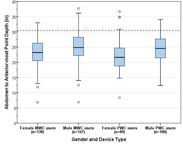
Figure 1: Boxplot showing the distribution for abdomen depth (inches) across wheelchair type and occupant gender. The dotted line (30.5 in) depicts the 95th percentile value for female wheelchair users, both manual and power.
Note on Multivariate Analysis
The above univariate analysis is only applicable in the case of one critical dimension (i.e., abdomen to anterior-most point depth) and all other knee clearance dimensions are unrestricted or unbounded. If more than one dimension is bounded (e.g., combinations of knee clearance height or depth, foot clearance height or depth, occupied width, etc.) then a multivariate analysis which involves simultaneous consideration of multiple dimensions is more appropriate for performing clearance assessments. As the number of dimensions in the multivariate analysis increases it is possible that the resulting space requirements are larger in comparison to the univariate case where each dimension is analyzed separately.
2. Analysis of footrest clearance height and depth
Any base support or flange for the mammography machine at floor level (inside the clear floor space width) would obstruct some wheelchair users from approaching the mammography machine. The purpose of this analysis was to determine suitable dimensions for the base flange depth and thickness at floor level to minimize obstructions in forward approach for such users.
Over 30% of manual wheelchair users in this sample did not use footrests. Detailed footrest measurements (i.e., foot rest height and corner points on the top surface) were collected from 158 manual wheelchair users and 108 power wheelchair users. Footrests were present and recorded on the right-side for 101 (64%) manual wheelchair users and 105 (97%) of power wheelchair users. Front castor and footrest measurements were available for 67 power wheelchair users (excluding front-wheel drives for this analysis, due to time constraints). Three dimensions were computed on the right-side for the sub-set of wheelchairs with footrests:
-
Abdomen-Castor edge depth: measured as the horizontal distance from the abdomen to the distal (forward-most) edge of the front castor measured at castor hub height
-
Abdomen-Footrest distal depth: measured as the horizontal distance from the abdomen to the distal (forward-most) edge of the footrest
-
Footrest height: measured as the height from the floor to the top surface of the footrest at the proximal (near) outside corner
Both depth dimensions are referenced to the abdomen assuming that the wheelchair occupant makes contact with the breast-platform at the abdomen. The range and median values measured on the right-side for these three dimensions are presented in table 2. Critical values are highlighted in yellow. For each dimension, the more conservative estimate across manual and power wheelchairs is recommended. Based on the data in Table 2 we recommend that:
-
The total knee clearance depth should preferably be no less than 30 in. to minimize contact with the footrest (i.e., 95th percentile value for Abdomen-Footrest Distal depth). The abdomen-anterior-most point depth presented in the previous section is a preferred dimension as the feet/toes often go past the footrest.
-
Any flange or base support should preferably be no deeper than the overall clearance depth (e.g., 32 in. or 30 in.) minus the 95th percentile value for abdomen-castor edge depth. For example, for power wheelchair users, recommended flange depth = 30 in. – 19.3 in. = 10.7 in.
-
Any flange or base support thickness should preferably be less than the 5th percentile value of footrest height for manual wheelchair users minus the thickness of the footrest (assuming 0.5 in.), i.e., approx. 1.7-0.5 = 1.2 in.
Table 2: Observed ranges and percentile values for Abdomen-Castor edge depth, Abdomen-Footrest edge depth, and Footrest Height, measured on the right-side for manual and power wheelchair users (Note: combined data for male and female). Critical values are highlighted in yellow.

[Click image above to view HTML version]
Figures 2 and 3 provide scatter-plots showing the relationship between Abdomen-Castor edge depth (and castor hub height) and Abdomen-Footrest distal depth (at footrest height) referenced from the abdomen point measured on the right side for manual wheelchair users (fig. 2) and power wheelchair users (fig. 3) respectively.
Assuming a 30 in. knee clearance depth, sample profiles of flanges based on the footrest measurements for manual and power wheelchair users are also shown. Although the flange depth and thickness is limited (e.g., 1-1.5 in.) the data suggests that the flange thickness could be increased closer to the base of the machine e.g., a triangular profile.
Further, it can be assumed that individuals that did not have a footrest (over 30% of manual wheelchair users) have some lower extremity mobility and would be able to lift and place their feet on top of the flange/base.
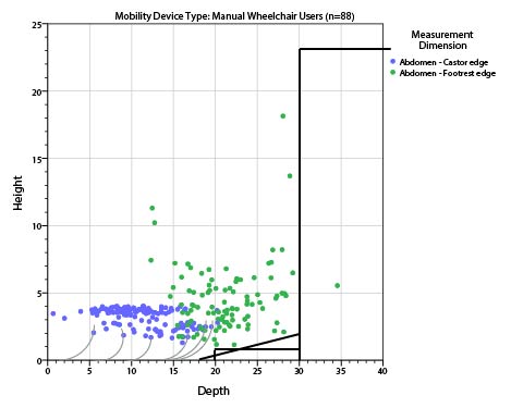
Figure 2: Scatter-plot showing observed values footrest height (on the vertical axis) and Castor-Footrest Depth (on the horizontal axis) measured on the right-side for manual wheelchair users referenced to the abdomen point. The grey curves show sample profiles of castor-wheels.
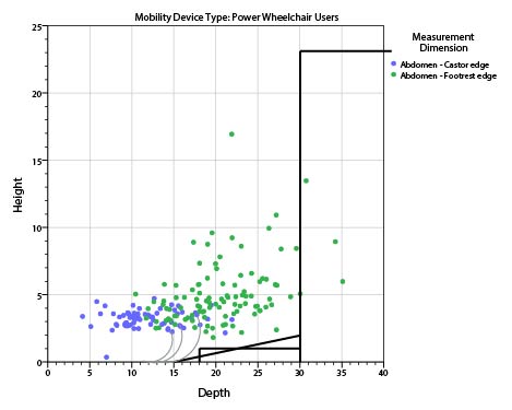
Figure 3: Scatter-plot showing observed values footrest height (on the vertical axis) and Castor-Footrest Depth (on the horizontal axis) measured on the right-side for power wheelchair users referenced to the abdomen point. The grey curves show sample profiles of castors-wheels.
Conclusions
Design criteria based on the univariate analysis of abdomen depth is sufficient if all other clearance dimensions are unbounded (i.e., unrestricted) and abdomen depth is the only relevant dimension. The 95th percentile value for female users of manual and power wheelchairs was approximately 30.5 in. and would provide adequate clearance depth such that approximately 95% of female users can approach the machine up to the abdomen.
Analysis of the footrest clearance height, abdomen-castor depth and abdomen-footrest depth suggests a flange of depth 10-10.7 in. and thickness 1-1.2 in. maximum. However, a graphical plot of the data suggests that the flange thickness could be increased closer to the base of the machine e.g., with a gradient or triangular profile.
IDeA Center, University at Buffalo
Memorandum:
Date: 10/23/2012
From: Clive D’Souza and Edward Steinfeld, IDeA Center, University at Buffalo
To: Rex Pace, Technical Assistance Coordinator, U.S. Access Board
RE: Analysis of Transfer Surface Dimensions Based on Wheeled Mobility User Anthropometry
Summary
The following report provides a brief analysis of four anthropometric dimensions which were considered relevant to the width and depth dimensions of a seating surface for wheeled mobility device users. The data are based on findings from the Anthropometry of Wheeled Mobility (AWM) Project, and comprises of detailed static measurements collected from 500 users of manual wheelchairs, power wheelchairs and scooters.
This analysis focuses only on the adequacy of the proposed transfer surface dimensions as a static seating surface – i.e., no measurements of transfers were recorded. The proposed dimensions for transfer surface 30in. wide and 15in. deep is estimated to be adequate as minimum criteria for a static seating surface. Our
research findings demonstrate that the minimum width of the surface could be as small as 28 in. and still accommodate 95% of our sample. It should be noted that Additional width may be required for accommodating users that are morbidly obese or use bariatric wheelchairs. Furthermore, additional space may be needed to accommodate the task of transferring, depending on the additional features provided, e.g. armrests or railings. User testing is recommended for arriving at more accurate transfer surface dimensions and design features to insure usability for a broad diversity of users, including individuals with mobility impairments.
Introduction
The proposed guidelines for medical diagnostic equipment recommends a minimum transfer surface 30 in. (760mm) wide and 15 in. (381mm) deep. At the request of the U.S. Access Board staff, a brief analysis was performed based on static anthropometry measurements previously collected to evaluate the adequacy of these transfer surface dimensions.
The Center for Inclusive Design and Environmental Access (IDeA) at the University at Buffalo conducted an anthropometric study of 500 individuals who use wheeled mobility devices (WMD)1. The research included the collection of demographic information and WMD characteristics, and the measurement of structural and functional anthropometry. Data collection included 3 dimensional measurements of approximately 90 points located on the body and device. Linear distances between pairs of measured points can be computed to provide dimensional estimates of body and mobility device sizes.
Four static body dimensions considered relevant to the width and depth dimensions of a seating surface were computed and analyzed to serve as a reference. These dimensions include: thigh breadth, shoulder breadth, buttock-popliteal length, and wheelchair seat depth. Dimension values are stratified by gender and mobility device type since significant differences in size and space requirements exist across these sub-groups. All dimensions are based on occupant static postures while seated in their own mobility device. As such, the analysis focuses only on the adequacy of the proposed transfer surface dimensions for a static seating surface. No measurements of transferring to or from the mobility device were recorded. Hence, the dimensions discussed in this report should only be considered as a starting point for accessible design of a seating surface. When determining space requirements for dynamic transfer tasks, there are additional space needs and functional abilities of the user population which must be considered. For example, individuals may need additional space to position their hands when conducting a side transfer. Issues of comfort and security need to be considered. Tasks that are performed on the table, like rolling over, need to be accommodated. Furthermore, the question of how to accommodate morbidly obese individuals still needs to be addressed.
The charts below were developed using a statistical analysis package with some built-in features. The reader will notice data points noted as “extreme values.” The statistical package analyses the data to identify “outliers,” or values that exceed expected values in data with a normal distribution. It then includes those values in the graphics as outside the range of maximum and minimum values in each distribution. The charts serve as a visual aid for understanding how the diversity or spread in measurement values within and between each of the six sub-groups of device users that were studied.
However, the “extreme values” are included in our assessment and recommendations on accommodating 95% of the sample, since these “extreme values” represent genuine cases of individuals (as opposed to errors in measurement) that need to be accommodated by design and hence should not be excluded from the analysis, and, the dimensions that we analyzed were not normal distributed due to a broad diversity in the observed measurements. Hence the percentiles were computed separately based on the observed data and not an implied normal distribution. Readers can assume that these “extreme values” represent unusually large or small dimensions for the population studied that might need special accommodation through design and/or some type of personal assistance.
1. Thigh Breadth
Thigh breadth was used to provide an estimate of the width of the seating surface. Thigh breadth for this analysis was computed as the larger of two dimensions, the horizontal distance between the lateral (outer) aspect of the hips, and the horizontal distance between the lateral aspects of the thighs, when seated in the wheelchair and not considering any wheelchair hardware. Figure 1 provides a box-plot showing the distribution for thigh breadth stratified by gender and mobility device type. It should be noted that the thigh breadth dimension for manual and power wheelchair users may be underestimated due to lateral posture support features (such as double-post armrest, wheelchair side guard). Scooters generally have single post armrests and hence the occupants’ thighs are laterally “unsupported” and tend to be wider reflecting a more natural posture. In wheelchairs, the armrests and side guards could compress overall breadth of the thighs to a certain extent.
Inadequate seat width can be more problematic for individuals that have broader hips and/or thighs. As such, the width dimension should be based on the higher end of the sample distribution to provide a sufficient base of support for as large a proportion of the user population as possible (e.g., 95th or 99th percentile). The 95th percentile and maximum values across the 6 sub-groups were within a range of 22in-28in, and the maximum values were within the 26in-30in. range. A minimum width of 30in would therefore ensure that all individuals of our sample would be accommodated in terms of the width of a static seating surface. If the minimum width were reduced to 28 in. only three individuals in our sample would not be accommodated.
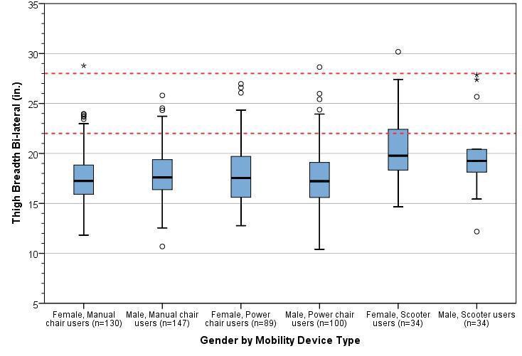
Figure 1: Box-plot showing the distribution for thigh breadth stratified by gender and mobility device type. The horizontal line splitting the box depicts the median, the box length represents the inter-quartile (25th – 75th percentile) range, and the whiskers represent the minimum and maximum values. Extreme values are shown as dots and asterisks. The red dotted lines depict the observed range of 95th percentile values across sub-groups.
2. Shoulder Breadth
Shoulder breadth tends to be slightly greater than hip or thigh breadth and hence was used as an estimate for the width of an examination table when in a reclined position. Shoulder breadth was computed as the horizontal distance between the lateral (outer) aspects of the deltoids. Figure 2 provides a box-plot showing the distribution for shoulder breadth stratified by gender and mobility device type.
Inadequate seat width can be more problematic for individuals that have broader shoulders and/or are obese. As such, the width dimension should be based on the higher end of the sample distribution to provide a sufficient base of support for as large a proportion of the user population as possible (e.g. 95th or 99th percentile). The 95th percentile values across the 6 sub-groups ranged from 23-27.5 in., and the maximum values ranged from 25-34 in. A minimum width of 30in. would ensure that all individuals of our sample would be accommodated in terms of static body width. However, space for tasks such as turning over to the side when reclining is not being considered.
A wider examination table (i.e., greater than 30in.) may be needed if accommodating individuals that are morbidly obese and/or use bariatric wheelchairs is also a priority. Our study sample is not representative in terms of the bariatric wheelchair user population – i.e., we had only one bariatric wheelchair user in the sample although we did have many people who were quite obese. The outlier values across thigh breadth and shoulder breadth might serve as a reference for determining the needs of morbidly obese individuals who use wheeled mobility devices (e.g., 34 in.).
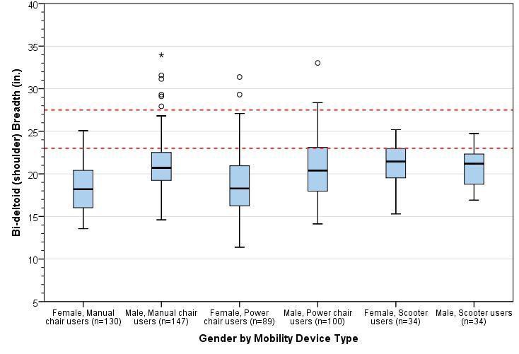
Figure 2: Box-plot showing the distribution for shoulder breadth stratified by gender and mobility device type. The horizontal line splitting the box depicts the median, the box length represents the inter-quartile (25th – 75th percentile) range, and the whiskers represent the minimum and maximum values. Extreme values are shown as dots and asterisks. The red dotted lines depict the observed range of 95th percentile values across sub-groups.
3. Buttock-Popliteal Length
For this study, an estimate of buttock-popliteal length was calculated as the horizontal distance from the proximal (rear) edge of the wheelchair seat cushion to the popliteal fossa (i.e., crease at the back of the knee) of the right leg. The median buttock-popliteal length provides an upper bound for the depth of a seating surface. If seat depth is increased beyond this length, it becomes difficult to engage the backrest as well as exerting pressure to the back of the knees. Figure 3 provides a box-plot showing the distribution for shoulder breadth stratified by gender and mobility device type. The median (50th percentile) values for buttock-popliteal length across the 6 sub-groups ranged from 18.5-19.5 in. Seat depths should preferably not exceed these values (see next section for more information).
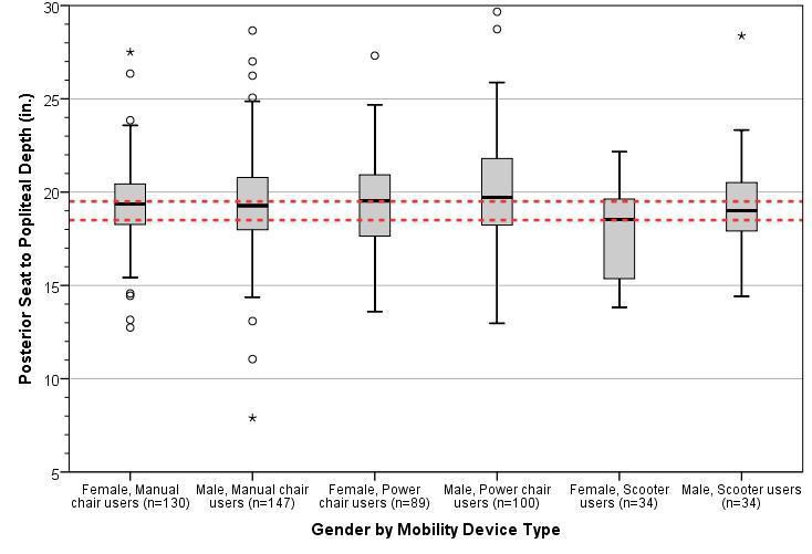
Figure 3: Box-plot showing the distribution for approximate buttock-popliteal length stratified by gender and mobility device type. The horizontal line splitting the box depicts the median, the box length represents the inter-quartile (25th – 75th percentile) range, and the whiskers represent the minimum and maximum values. Extreme values are shown as dots and asterisks. The red dotted lines depict the observed range of 95th percentile values across sub-groups.
4. Wheelchair seat depth
For this study, wheelchair seat depth was calculated as the horizontal distance from the proximal (i.e., towards the rear) edge to the distal (i.e., towards the forward) edge of the wheelchair seat cushion. Individual wheelchair seat depths are generally about 2 in. less than buttock-popliteal length in most case – this is a rough guideline and is quite similar to deciding seat depths for ambulatory individuals e.g., for office chairs. The median seat depth across different wheeled mobility devices would provide a reference value for the depth of other common seating surfaces. Figure 4 provides a box-plot showing the distribution for wheelchair seat depth stratified by gender and mobility device type.
The median (50th percentile) values for wheelchair seat depth across the 6 sub-groups ranged from 14-17 in. The proposed guidelines recommend a transfer surface depth of 15in. which is at about the middle of this range and may be appropriate.
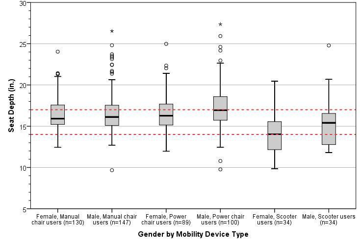
Figure 4: Box-plot showing the distribution for approximate wheelchair seat depth stratified by gender and mobility device type. The horizontal line splitting the box depicts the median, the box length represents the inter-quartile (25th – 75th percentile) range, and the whiskers represent the minimum and maximum values. Extreme values are shown as dots and asterisks. The red dotted lines depict the observed range of 95th percentile values across sub-groups.
Conclusions
The proposed guidelines for medical diagnostic equipment currently recommend a minimum transfer surface
30 in. (760mm) wide and 15 in. (381mm) deep. Our findings support those dimensions but also suggest that
the width could be reduced to 28 in. Our analysis based on static anthropometry measurements. It focuses solely on the adequacy of these transfer surface dimensions for a static seating surface. No studies or measurement of transfers were recorded nor did we collect information on the space needs of other tasks on exam tables like repositioning the body for exams.
Based on an anthropometric analysis of four relevant dimensions, we have the following observations and recommendations:
-
The proposed minimum transfer surface width of 30 in. provides sufficient space as a static seating surface for almost all individuals in our sample of wheeled mobility users based on static measurements of hip and thigh breadth. This width could be reduced to 28 in. and still accommodate 95% of our sample.
-
A width of 30 in. would also accommodate the shoulder breadth of most individuals should this be required, e.g., when the table is in a reclined position. Reducing this width to 28 in. would still accommodate 95% of our sample.
-
Increasing the minimum width is recommended if accommodating individuals that are morbidly obese and/or use bariatric wheelchairs is also a priority. The maximum values recorded for thigh breadth and shoulder breadth serves as a reference value should accommodations for these users be necessary.
-
A depth of 15in. for a seating surface was found to be suitable based on median values of buttock-popliteal length and wheelchair seat depths.
-
These results reflect static anthropometry measurements and should be considered as a starting point for accessible design of a seating surface. User testing is recommended for arriving at more accurate transfer surface dimensions and design features to insure usability for a broad diversity of users and the full range of tasks that might take place on an exam table.
Notes:
1. Steinfeld, E., Paquet, V., D'Souza, C., Joseph, C., Maisel, J., 2010. Final Report: Anthropometry of Wheeled Mobility Project. Prepared for the U.S. Access Board. IDeA Center, Buffalo, NY.
IDeA Center, University at Buffalo
Date: 3/20/2013
From: Clive D’Souza and Edward Steinfeld, IDeA Center, University at Buffalo
To: Marsha Mazz, U.S. Access Board
RE: Summary analysis of wheelbase measurements on wheeled mobility devices
Wheelbase Definition
For the purpose of this analysis, wheelbase is defined as the distance from the center of the primary drive wheel to the center of the caster measured parallel to the floor. The larger of the dimensions measured on the right and left side of the mobility device were considered for the analysis.
The sample considered is the analysis of wheelbase is a sub-set comprising 242 the overall sample of 500 wheeled mobility users. Only one set of casters on mid-wheel drive wheelchairs were measured and so these devices are not excluded in the current analysis.
Table 1 shows the minimum, maximum and percentile values of the wheelbase dimension for manual wheelchairs, front- and rear-wheel drive power chairs, 3- and 4-wheel electric scooters.
Table 1: Range and percentile values for wheelbase (inches) by mobility device type

[Click image above to view HTML version]
Introduction
The following memo is a brief analysis of the wheelbase dimension for wheeled mobility devices in the anthropometry of wheeled mobility database.
Observations:
-
Wheelbase dimensions for manual wheelchairs and rear-wheel drive power chairs were similar to each other but slightly less than the wheelbase for front wheel drive power chairs
-
Both 3- and 4- wheeled electric scooters had a larger wheelbase dimensions compared to manual and power wheelchairs. This sample had just three 4-wheeled scooters which limits detailed comparisons with 3-wheeled scooters
For platforms designed to accommodate wheeled mobility devices, additional space beyond the wheelbase should be provided. It would be very difficult for the occupant to have the powered device come to rest on a platform that is the exact length as its wheelbase or even a few inches more. Fine control (for example less than 1 in. increments) is difficult when operating powered wheelchair and scooter devices.
The wheelchair scale we used had a leveled surface of length 30 in. long with a bevel of 5 in. each at both ends (i.e., total length of 40 in.). Power wheelchair and scooter users often had trouble getting positioned exactly on the leveled portion of the platform requiring additional time and verbal assistance from an assistant/aide to get properly situated. Larger devices including power wheelchairs would often get positioned with two wheels on the bevel edge. We have observed that this causes an uneven weight distribution on the scale and could cause power wheelchairs to tip over when making short quick forward-reverse maneuvers in trying to get positioned on the platform. Including some aids to facilitate positioning would be a good idea also, for example, lines on either end with contrasting color and raised ridges at the ends of the level part of the platform.
Recommendations
Based on the data in Table 1 and the observations above, we recommend:
-
a minimum flat surface of 40 in. length for platforms accommodating wheeled mobility devices including scooters
-
a minimum flat surface of 33 in. length for platforms accommodating wheeled mobility devices excluding scooters
-
aids that can help wheelchair users mount the platform and position their chairs fully on the level surface.
User Comments/Questions
Add Comment/Question