36 CFR Part 1195 Proposed Accessibility Standards for Medical Diagnostic Equipment - Example Applications of Proposed Standards
Example Applications of the Proposed Medical Diagnostic Equipment Accessibility Standards
January 23, 2012
Figure M1: Overview of M301 Diagnostic Equipment for Use by a Patient in a Supine, Prone, or Side-Lying Position
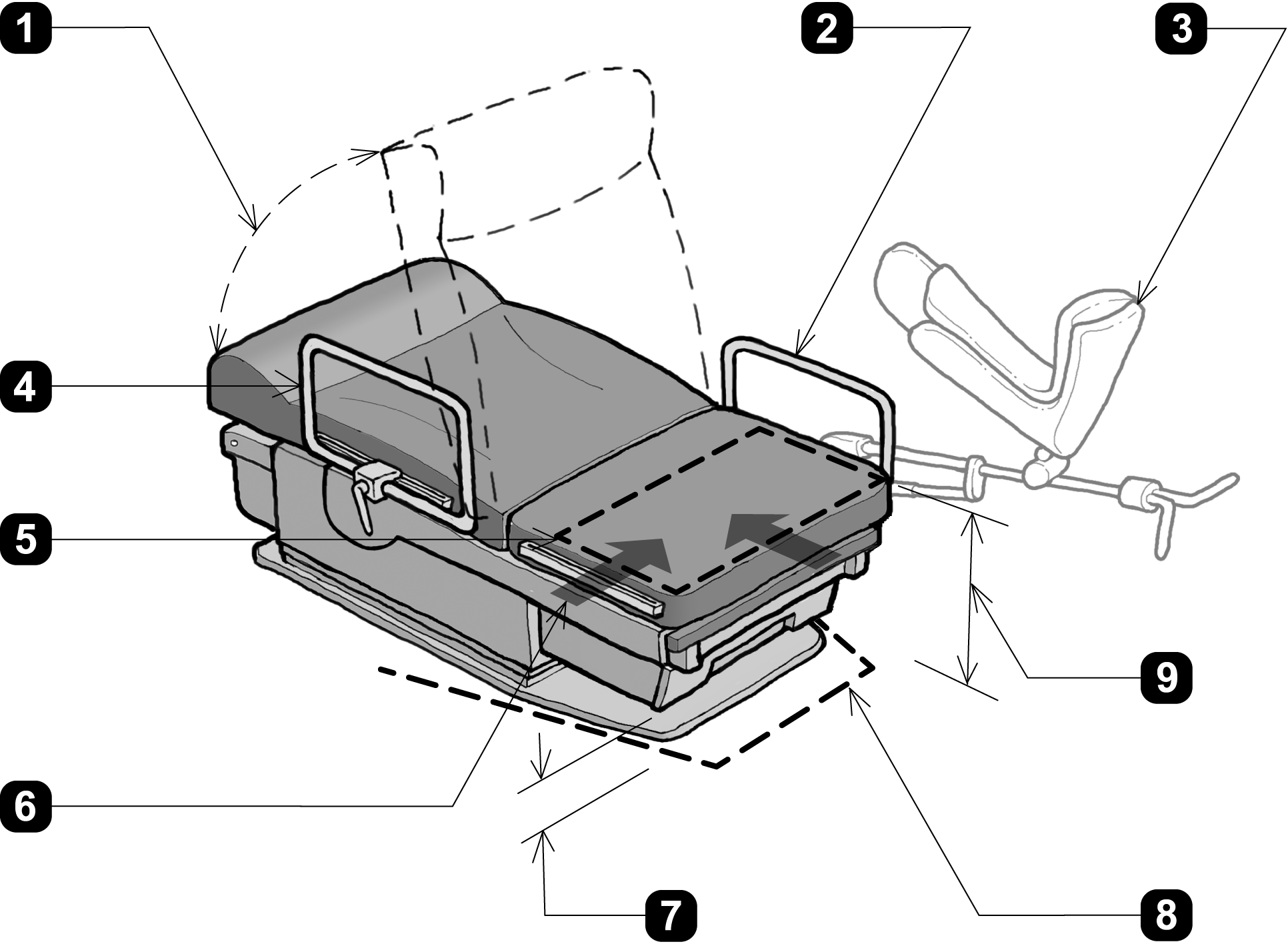
1. when adjustable, head and back support provided throughout the entire range of the incline (M301.3.3)
2.
- transfer support resists vertical and horizontal forces of 250 lbs at all points and does not rotate within it’s fittings (M305.2.2 and M305.2.3)
- rail serves as transfer support within reach of transfer surface (M301.3.1 and M305.2.1)
3. when provided, stirrups provide a method of supporting, positioning, and securing the patient’s leg (M301.3.2)
4. support rail removable / repositioned to permit unobstructed transfer (M301.2.3 EXCEPTION)
5. transfer surface 30 inches (760 mm) wide min. and 15 inches (381 mm) deep min. (M301.2.2)
6. one short side (depth) and one long side (width) of the transfer surface permit unobstructed transfer from a mobility device (M301.2.3)
7. 6 inches (150 mm) high min. clear above finished floor where equipment overhangs clearance (M301.4.1)
8. base permits clearance around base for a patient portable floor lift, see Figure M2 (M301.4 and M301.4.2)
9. transfer surface 17 inches (430 mm) min. and 19 inches (485 mm) max. above floor (M301.2.1), when not needed to facilitate transfer, the transfer surface may be positioned above or below the height range (Advisory M301.2.1)
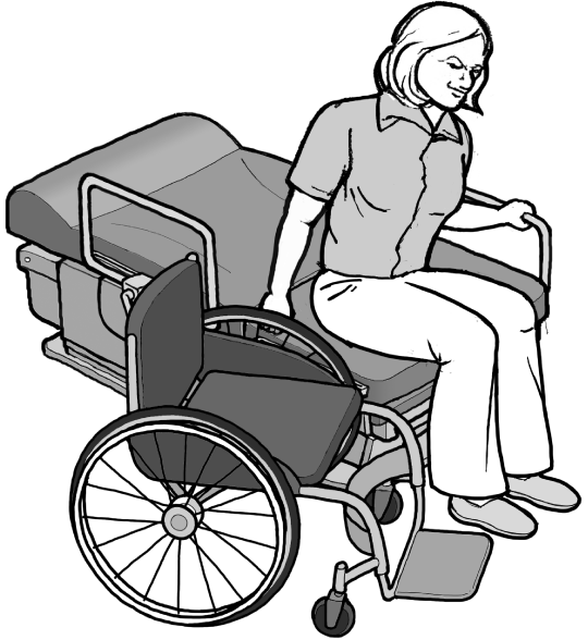
transfer to short side (depth) of transfer surface
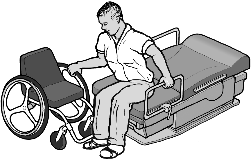
transfer to long side (width) of transfer surface
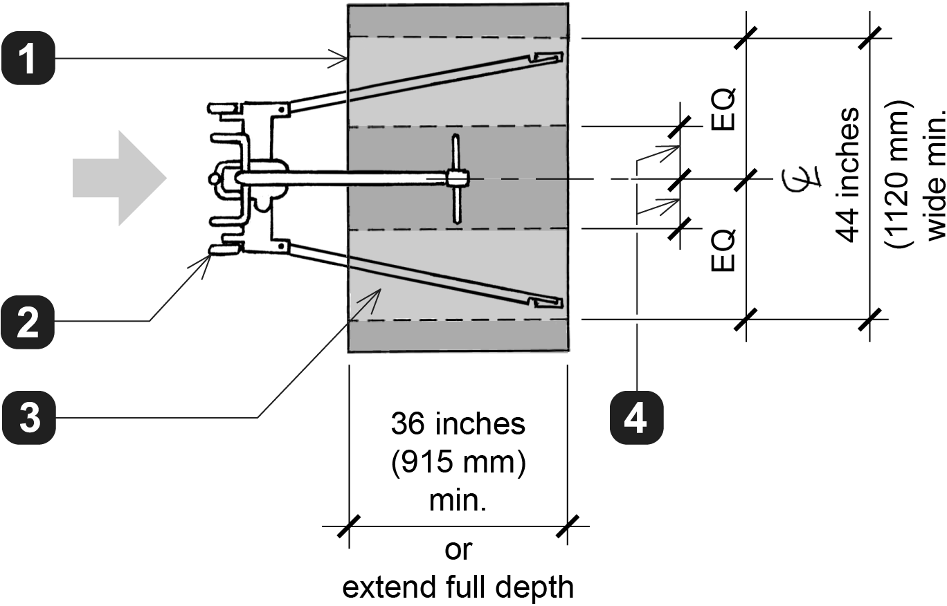
Figure M2: M301.4 Lift Compatibility
(at Diagnostic Equipment for Use by a Patient in a Supine, Prone, or Side-Lying Position)
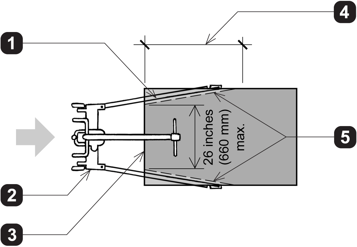
1. 6 inches (150 mm) high min. clear above finished floor
2. patient lift
3. examination surface
4. clearance must extend 36 inches (915 mm) min. deep from the edge of the examination surface
5. base is permitted to increase in width at a rate of 1 inch (25 mm) in width for each 3 inches (75 mm) in depth within clearance
M301.4.1 Clearance in Base
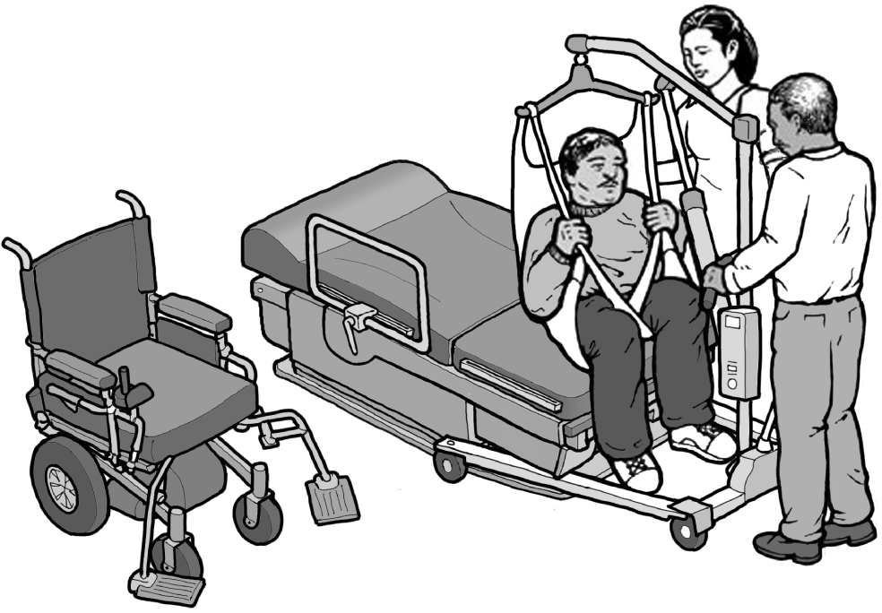
the clearances required for lift compatibility permits equipment to be usable with a patient portable floor lift
M301.4.2 Clearance Around Base
1. examination surface
2. patient lift
3. 6 inches (150 mm) high min. clear above finished floor within clearance
4. 8 inches (205 mm) max.
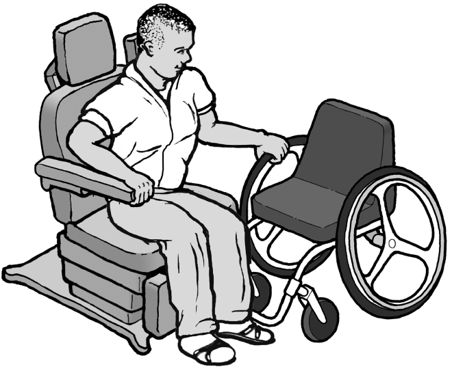
Figure M3: Overview of M302 Diagnostic Equipment for Use by a Patient in a Seated Position
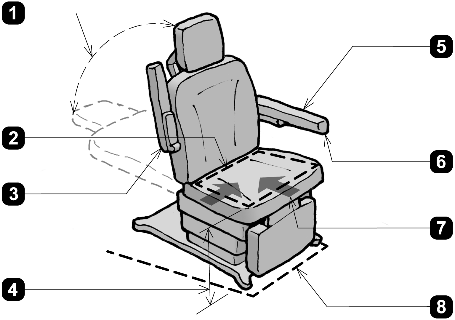
1. when adjustable, head and back support provided throughout the entire range of the incline (M302.3.3)
2. transfer surface 21 inches (760 mm) wide min. and 15 inches (381 mm) deep min. (M302.2.2)
3. armrest folds up to permit unobstructed transfer (M302.2.3 EXCEPTION)
4. transfer surface 17 inches (430 mm) min. and 19 inches (485 mm) max. above floor (M302.2.1), when not needed to facilitate transfer, the transfer surface may be positioned above or below the height range (Advisory M302.2.1)
5. required armrest serves as transfer support within reach of transfer surface (M302.3.1, M302.3.2, and M305.2.1)
6. transfer support resists vertical and horizontal forces of 250 lbs at all points and does not rotate within it's fittings (M305.2.2 and M305.2.3)
7. one short side (depth) and one long side (width) of the transfer surface permit unobstructed transfer from a mobility device (M302.2.3)
8. base permits clearance around base for a patient portable floor lift (M302.4 and M302.4.2)
transfer to short side (depth) of transfer surface
transfer to long side (width) of transfer surface
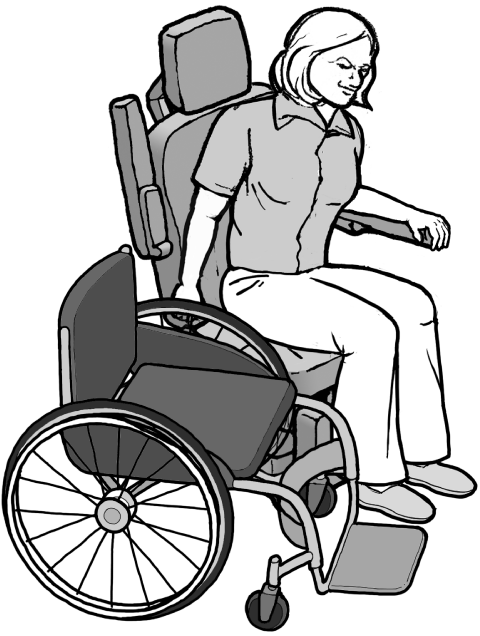
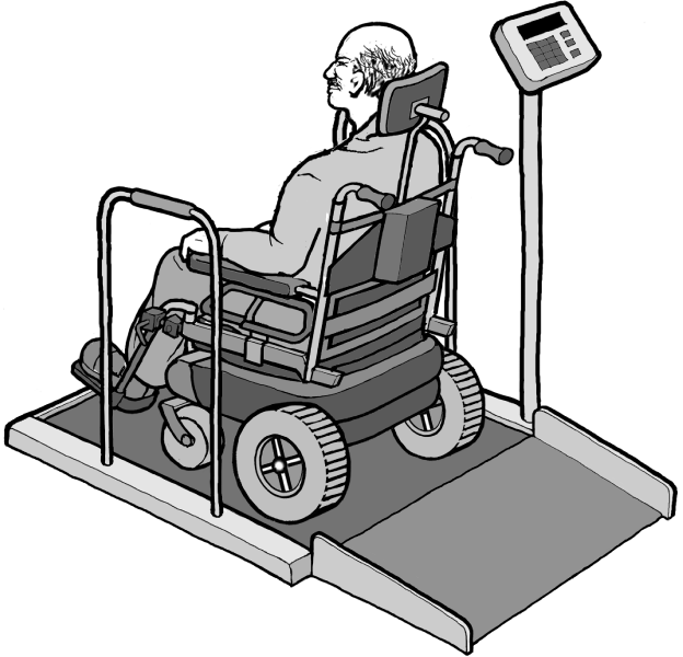
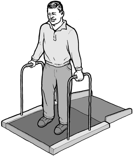
Figure M4: Overview of M303 Diagnostic Equipment for Use by a Patient While Seated in a Wheelchair and M304 Diagnostic Equipment for Use by a Patient in a Standing Position (Weight Scale Example)
Where the primary use of the equipment supports more than one patient position, it must comply with the requirements for each use. The weight scale is usable by both people who are seated in wheelchairs and those who stand and must meet the requirements of both Sections M303 and M304. (M101.2)
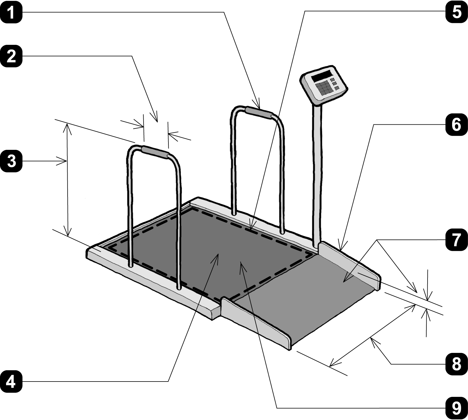
1. standing support on each side of standing surface (M304.3)
2. horizontal supports with gripping surfaces 4 inches (100 mm) min. long (M305.3.1)
3.
- top of gripping surfaces for horizontal supports 34 inches (865 mm) high min. and 38 inches (965 mm) high max. above standing surface (M305.3.1)
- standing supports do not rotate within their fittings (M305.3.3)
4. slip resistant surface (M304.2)
5. 36 inches (915 mm) wide min. and 48 inches (1220 mm) deep min. wheelchair space (M303.2.2 and M303.2.3)
6. 2 inches (50 mm) high min. edge protection on each side of ramp slope for drop-offs exceeding ½ inch (M303.3.3.4)
7. change in level greater than ½ inch is ramped with a running slope no steeper than 1:12 and cross slopes no steeper than 1:48 (M303.3.3, M303.3.3.1, and M303.3.3.2)
8. clear width of ramp run 36 inches (915 mm) min. (M303.3.3.3)
9. wheelchair space surface does not slope more than 1:48 in any direction (M303.2.5)
transfer to short side (depth) of transfer surface
transfer to long side (width) of transfer surface
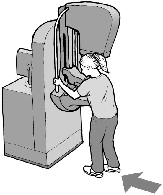
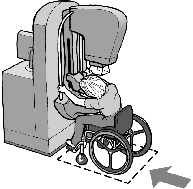
Figure M5: Overview of M303 Diagnostic Equipment for Use by a Patient While Seated in a Wheelchair and 304 Diagnostic Equipment for Use by a Patient in a Standing Position (Mammography Machine Example)
Where the primary use of the equipment supports more than one patient position, it must comply with the requirements for each use. The mammography machine is usable by both people who are seated in wheelchairs and those who stand and must meet the requirements of both Sections M303 and M304. (M101.2)
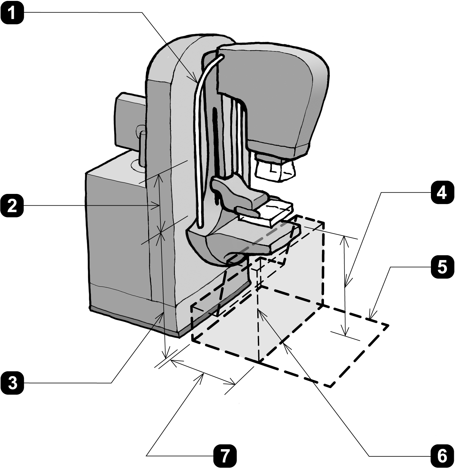
1.
- standing support on each side of standing surface (M304.3)
- standing supports do not rotate within their fittings (M305.3.3)
2. vertical gripping surfaces 18 inches (455 mm) long min. (M305.3.2)
3. bottom of vertical gripping surface 34 inches (865 mm) high min. and 37 inches high (940 mm) max. above standing surface (M305.3.2)
4. breast platform 30 inches (760 mm) high min. and 42 inches (1065 mm) high max. above floor when used by a patient seated in a wheelchair (M303.4 and M303.4.1)
5.
-. 36 inches (915 mm) wide min. and 48 inches (1220 mm) deep min. wheelchair space (M303.2.2 and M303.2.3)
- wheelchair space surface slopes no more than 1:48 in any direction (M303.2.5)
6. wheelchair space includes knee and toe clearance complying with M303.2.4, see Figure M6 (M303.2.4, M303.2.4.1, and M303.2.4.2)
7. knee and toe space under breast platform 25 inches (635 mm) deep (M303.2.4)
wheelchair space orients in the same direction as other patients using the diagnostic equipment (M303.2.1)
Figure M6: M303.2.4 Knee and Toe Clearance
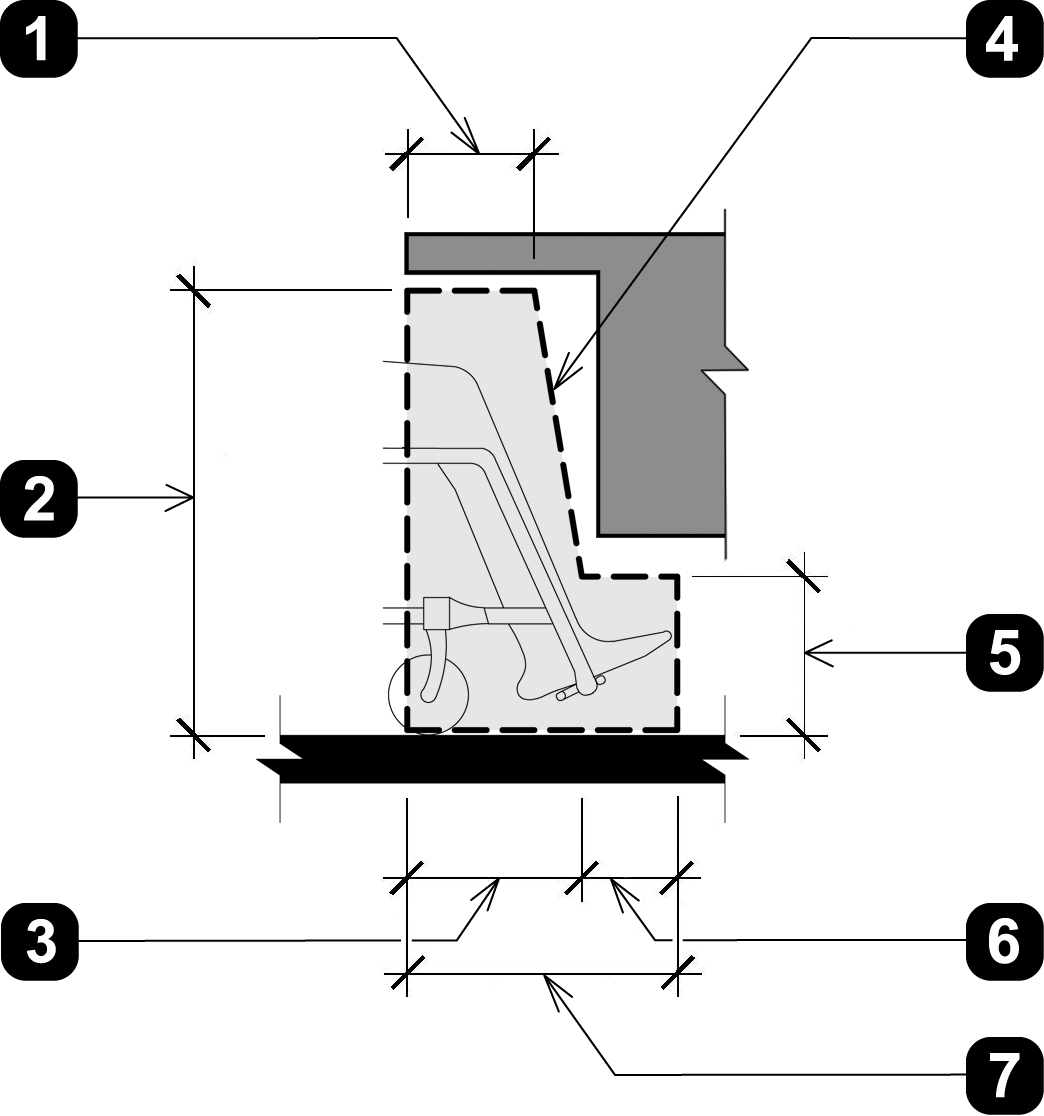
1. 8 inches (205 mm) deep min. knee clearance at 27 inches (685 mm) high min. (M303.2.4.2)
2. 27 inches min. (685 mm)
3. 11 inches (280 mm) min. and 25 inches (635 mm) max. deep knee clearance at 9 inches (230 mm) high (M303.2.4.2)
4. between 9 inches (230 mm) and 27 inches (685 mm) above the floor, the knee clearance is permitted to reduce at a rate of 1 inch (25 mm) in depth for every 6 inches (150 mm) in height (M303.2.4.2)
5. 9 inches (230 mm) high toe clearance (M303.2.4.1)
6. 6 inches (150 mm) deep max. toe clearance (M303.2.4.1)
7. the depth of the wheelchair space (M303.2) must include knee and toe clearance of 17 inches (430 mm) min. and 25 inches (635 mm) max., knee and toe clearance under breast platforms must be 25 inches (635 mm) deep, see Figure M5 (M303.2.4)
User Comments/Questions
Add Comment/Question