2013 California Standards for Accessible Design Pocket Guide
DIVISION 5: GENERAL SITE AND BUILDING ELEMENTS.
ETA Editor's Note
The following hyperlinks are provided to facilitate efficient navigation through this Pocket Guide:
TABLE OF CONTENTS
INTRODUCTION
CHAPTER 11B ACCESSIBILITY TO PUBLIC BUILDINGS, PUBLIC ACCOMMODATIONS, COMMERCIAL BUILDINGS AND PUBLIC HOUSING
DIVISION 1: APPLICATION AND ADMINISTRATION
DIVISION 2: SCOPING REQUIREMENTS
DIVISION 3: BUILDING BLOCKS
DIVISION 4: ACCESSIBLE ROUTES
DIVISION 5: GENERAL SITE AND BUILDING ELEMENTS
11B-501 General
11B-502 Parking Spaces
11B-503 Passenger Drop-Off and Loading Zones
11B-504 Stairways
11B-505 Handrails
DIVISION 6: PLUMBING ELEMENTS AND FACILITIES
DIVISION 7: COMMUNICATION ELEMENTS AND FEATURES
DIVISION 8: SPECIAL ROOMS, SPACES AND ELEMENTS
DIVISION 9: BUILT-IN ELEMENTS
DIVISION 10: RECREATION FACILITIES
INDEX OF FIGURES and TABLES
11B-501.1 Scope.
The provisions of Division 5 shall apply where required by Division 2 or where referenced by a requirement in this chapter.
11B-502.1 General.
Car and van parking spaces shall comply with Section 11B-502. Where parking spaces are marked with lines, width measurements of parking spaces and access aisles shall be made from the centerline of the markings.
Exception: Where parking spaces or access aisles are not adjacent to another parking space or access aisle, measurements shall be permitted to include the full width of the line defining the parking space or access aisle.
11B-502.2 Vehicle spaces.
Car and van parking spaces shall be 216 inches (5486 mm) long minimum. Car parking spaces shall be 108 inches (2743 mm) wide minimum and van parking spaces shall be 144 inches (3658 mm) wide minimum, shall be marked to define the width, and shall have an adjacent access aisle complying with Section 11B-502.3.
[2010 ADAS] 502.2 Vehicle Spaces. Car parking spaces shall be 96 inches (2440 mm) wide minimum and van parking spaces shall be 132 inches wide minimum, shall be marked to define the width, and shall have an adjacent access aisle complying with 502.3.
Exception: Van parking spaces shall be permitted to be 108 inches (2743 mm) wide minimum where the access aisle is 96 inches (2438 mm) wide minimum.
[2010 ADAS] EXCEPTION: Van parking spaces shall be permitted to be 96 inches (2440 mm) wide minimum where the access aisle is 96 inches (2440 mm) wide minimum.
ETA Editor's Note
The 2013 CBC dimensional requirements for accessible parking spaces and van accessible parking spaces are larger than those in 2010 ADAS.
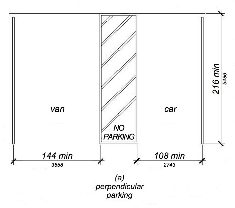
FIGURE 11B-502.2 ‡‡
VEHICLE PARKING SPACES
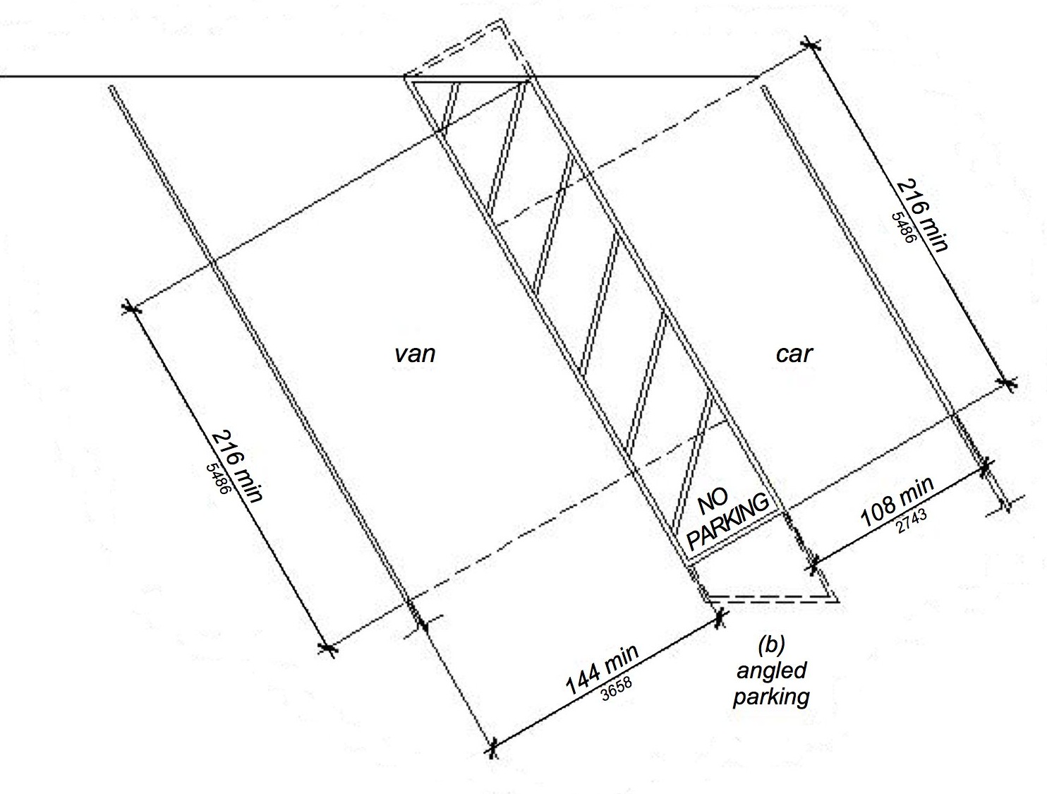
VEHICLE PARKING SPACES
11B-502.3 Access aisle.
Access aisles serving parking spaces shall comply with Section 11B-502.3. Access aisles shall adjoin an accessible route. Two parking spaces shall be permitted to share a common access aisle.
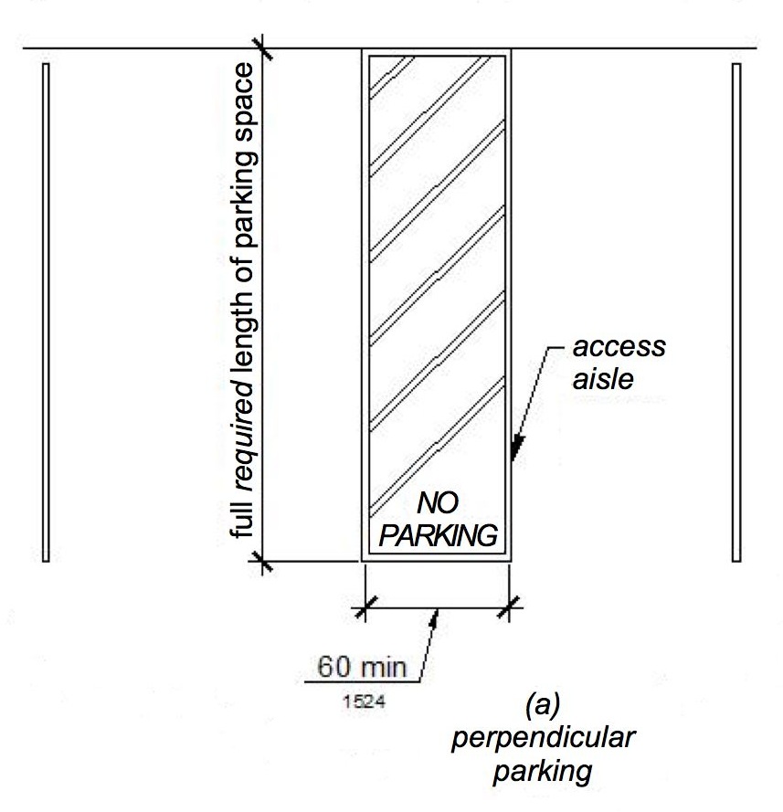
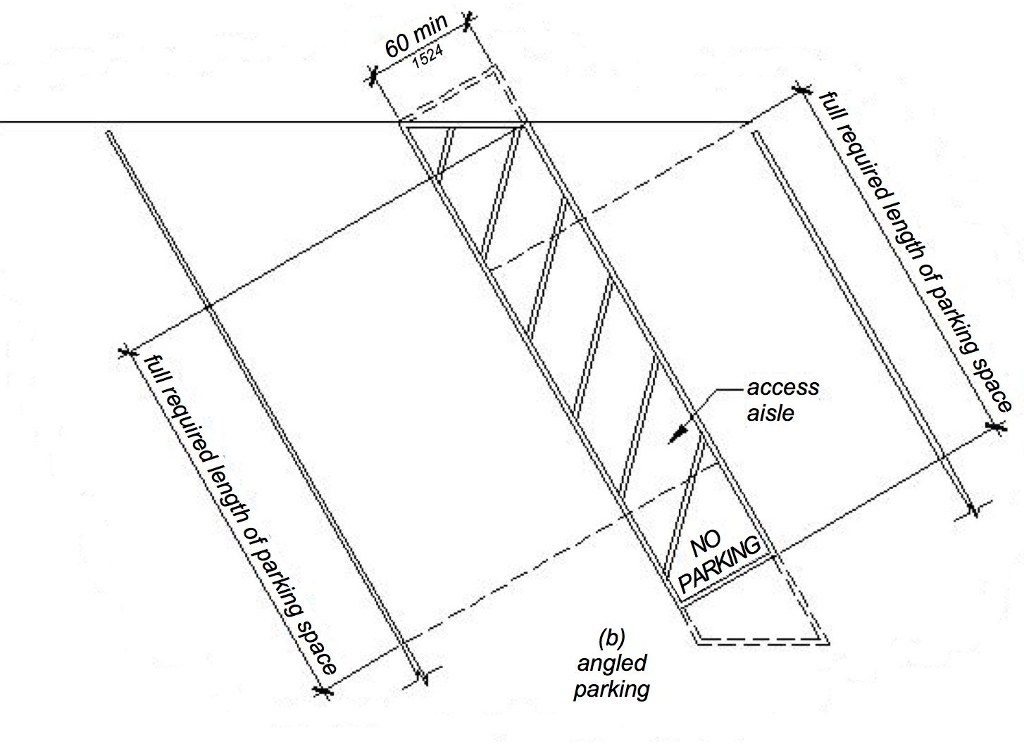
11B-502.3.1 Width.
Access aisles serving car and van parking spaces shall be 60 inches (1524 mm) wide minimum.
11B-502.3.2 Length.
Access aisles shall extend the full required length of the parking spaces they serve.
11B-502.3.3 Marking.
Access aisles shall be marked with a blue painted borderline around their perimeter. The area within the blue borderlines shall be marked with hatched lines a maximum of 36 inches (914 mm) on center in a color contrasting with that of the aisle surface, preferably blue or white. The words "NO PARKING" shall be painted on the surface within each access aisle in white letters a minimum of 12 inches (305 mm) in height and located to be visible from the adjacent vehicular way. Access aisle markings may extend beyond the minimum required length.
[2010 ADAS] 502.3.3 Marking. Access aisles shall be marked so as to discourage parking in them.

Asphalt is often the parking surface material used at accessible parking spaces. Asphalt is generally considered to be fairly dark in appearance. In order to provide a suitable contrasting color at the hatched area of the loading and unloading access aisle, a light color hatching should be used at locations where asphalt is the parking surface material. Although white paint is preferred (and traditionally the color most often used), its use is not mandatory under the California Building Code (CBC).
In order to provide a suitable contrast at the hatched area of the loading and unloading access aisle in locations where light concrete is used as the parking surface material (such as at concrete parking garages), a dark color hatching should be used. Although blue paint is preferred, its use is not mandatory under the California Building Code (CBC).◼
ETA Editor's Note
The 2013 CBC marking requirements for accessible parking spaces and van accessible parking spaces are more extensive than those in 2010 ADAS.
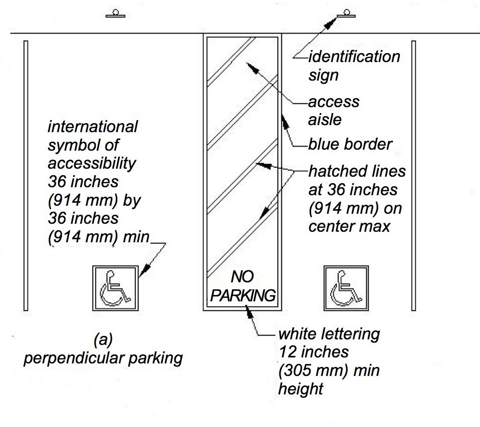
ANGLED AND PERPENDICULAR PARKING IDENTIFICATION
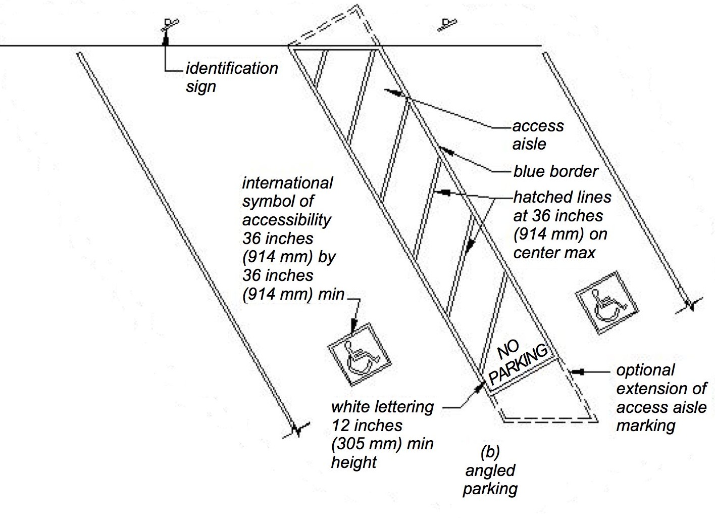
ANGLED AND PERPENDICULAR PARKING IDENTIFICATION
11B-502.3.4 Location.
Access aisles shall not overlap the vehicular way. Access aisles shall be permitted to be placed on either side of the parking space except for van parking spaces which shall have access aisles located on the passenger side of the parking spaces.
[2010 ADAS] 502.3.4 Location. Access aisles shall not overlap the vehicular way. Access aisles shall be permitted to be placed on either side of the parking space except for angled van parking spaces which shall have access aisles located on the passenger side of the parking spaces.
11B-502.4 Floor or ground surfaces.
Parking spaces and access aisles serving them shall comply with Section 11B-302. Access aisles shall be at the same level as the parking spaces they serve. Changes in level are not permitted.
Exception: Slopes not steeper than 1:48 shall be permitted.

11B-502.5 Vertical clearance.
Parking spaces, access aisles and vehicular routes serving them shall provide a vertical clearance of 98 inches (2489 mm) minimum.
[2010 ADAS] 502.5 Vertical Clearance. Parking spaces for vans and access aisles and vehicular routes serving them shall provide a vertical clearance of 98 inches (2490 mm) minimum.
ETA Editor's Note
2013 CBC requires 98 inches minimum vertical clearance at all accessible parking spaces, not solely van accessible parking spaces. This is more stringent than 2010 ADAS.
11B-502.6 Identification.
Parking space identification signs shall include the International Symbol of Accessibility complying with Section 11B-703.7.2.1. Signs identifying van parking spaces shall contain additional language or an additional sign with the designation “van accessible.” Signs shall be 60 inches (1524 mm) minimum above the finish floor or ground surface measured to the bottom of the sign.
[2010 ADAS] 502.6 Identification. Parking space identification signs shall include the International Symbol of Accessibility complying with 703.7.2.1. Signs identifying van parking spaces shall contain the designation "van accessible." Signs shall be 60 inches (1525 mm) minimum above the finish floor or ground surface measured to the bottom of the sign.

Exception: Signs located within an accessible route shall be a minimum of 80 inches (2032 mm) above the finish floor or ground surface measured to the bottom of the sign.
11B-502.6.1 Finish and size.
Parking identification signs shall be reflectorized with a minimum area of 70 square inches (45,161 mm2).
11B-502.6.2 Minimum fine.
Additional language or an additional sign below the International Symbol of Accessibility shall state “Minimum Fine $250.”
11B-502.6.3 Location.
A parking space identification sign shall be visible from each parking space. Signs shall be permanently posted either immediately adjacent to the parking space or within the projected parking space width at the head end of the parking space. Signs may also be permanently posted on a wall at the interior end of the parking space.
11B-502.6.4 Marking.
Each accessible car and van space shall have surface identification complying with either Section 11B-502.6.4.1 or 11B-502.6.4.2.
11B-502.6.4.1 .
The parking space shall be marked with an International Symbol of Accessibility complying with Section 11B-703.7.2.1 in white on a blue background a minimum 36 inches wide by 36 inches high (914 mm by 914 mm) . The centerline of the International Symbol of Accessibility shall be a maximum of 6 inches (152 mm) from the centerline of the parking space, its sides parallel to the length of the parking space and its lower corner at, or lower side aligned with, the end of the parking space length.
11B-502.6.4.2 .
The parking space shall be outlined or painted blue and shall be marked with an International Symbol of Accessibility complying with Section 11B-703.7.2.1 a minimum 36 inches wide by 36 inches high (914 mm by 914 mm) in white or a suitable contrasting color. The centerline of the International Symbol of Accessibility shall be a maximum of 6 inches (152 mm) from the centerline of the parking space, its sides parallel to the length of the parking space and its lower corner at, or lower side aligned with, the end of the parking space.
ETA Editor's Note
The 2013 CBC identification requirements for accessible parking spaces and van accessible parking spaces are more extensive than those in 2010 ADAS.
11B-502.7 Relationship to accessible routes.
Parking spaces and access aisles shall be designed so that cars and vans, when parked, cannot obstruct the required clear width of adjacent accessible routes.
11B-502.7.1 Arrangement.
Parking spaces and access aisles shall be designed so that persons using them are not required to travel behind parking spaces other than to pass behind the parking space in which they parked.

ETA Editor's Note
While 2010 ADAS Advisory 502.3 discourages configuring access aisles to require travel behind other parked vehicles, 2013 CBC 11B-502.7.1 prohibits this.
11B-502.7.2 Wheel stops.
A curb or wheel stop shall be provided if required to prevent encroachment of vehicles over the required clear width of adjacent accessible routes.
11B-502.8 Additional signage.
An additional sign shall be posted either; 1) in a conspicuous place at each entrance to an off-street parking facility or 2) immediately adjacent to on-site accessible parking and visible from each parking space.
11B-502.8.1 Size.
The additional sign shall not be less than 17 inches (432 mm) wide by 22 inches (559 mm) high.
11B-502.8.2 Lettering.
The additional sign shall clearly state in letters with a minimum height of 1 inch (25 mm) the following:
"Unauthorized vehicles parked in designated accessible spaces not displaying distinguishing placards or special license plates issued for persons with disabilities will be towed away at the owner’s expense. Towed vehicles may be reclaimed at _________________________ or by telephoning _______________________."
Blank spaces shall be filled in with appropriate information as a permanent part of the sign.
11B-503 Passenger drop-off and loading zones
[2010 ADAS] 503 Passenger Loading Zones
11B-503.1 General.
Passenger drop-off and loading zones shall comply with Section 11B-503.
[S.H. 1131B.2, Item 1] [Safe Harbor only applies to existing passenger drop-off and loading zones in the vicinity of, and leading to, a primary entrance.]
11B-503.2 Vehicle pull-up space.
Passenger drop-off and loading zones shall provide a vehicular pull-up space 96 inches (2438 mm) wide minimum and 20 feet (6096 mm) long minimum.
11B-503.3 Access aisle.
Passenger drop-off and loading zones shall provide access aisles complying with Section 11B-503 adjacent and parallel to the vehicle pull-up space. Access aisles shall adjoin an accessible route and shall not overlap the vehicular way.
11B-503.3.1 Width.
Access aisles serving vehicle pull-up spaces shall be 60 inches (1524 mm) wide minimum.
11B-503.3.2 Length.
Access aisles shall extend the full length of the vehicle pull-up spaces they serve.
11B-503.3.3 Marking.
Access aisles shall be marked with a painted borderline around their perimeter. The area within the borderlines shall be marked with hatched lines a maximum of 36 inches (914 mm) on center in a color contrasting with that of the aisle surface.
[2010 ADAS] 503.3.3 Marking. Access aisles shall be marked so as to discourage parking in them.
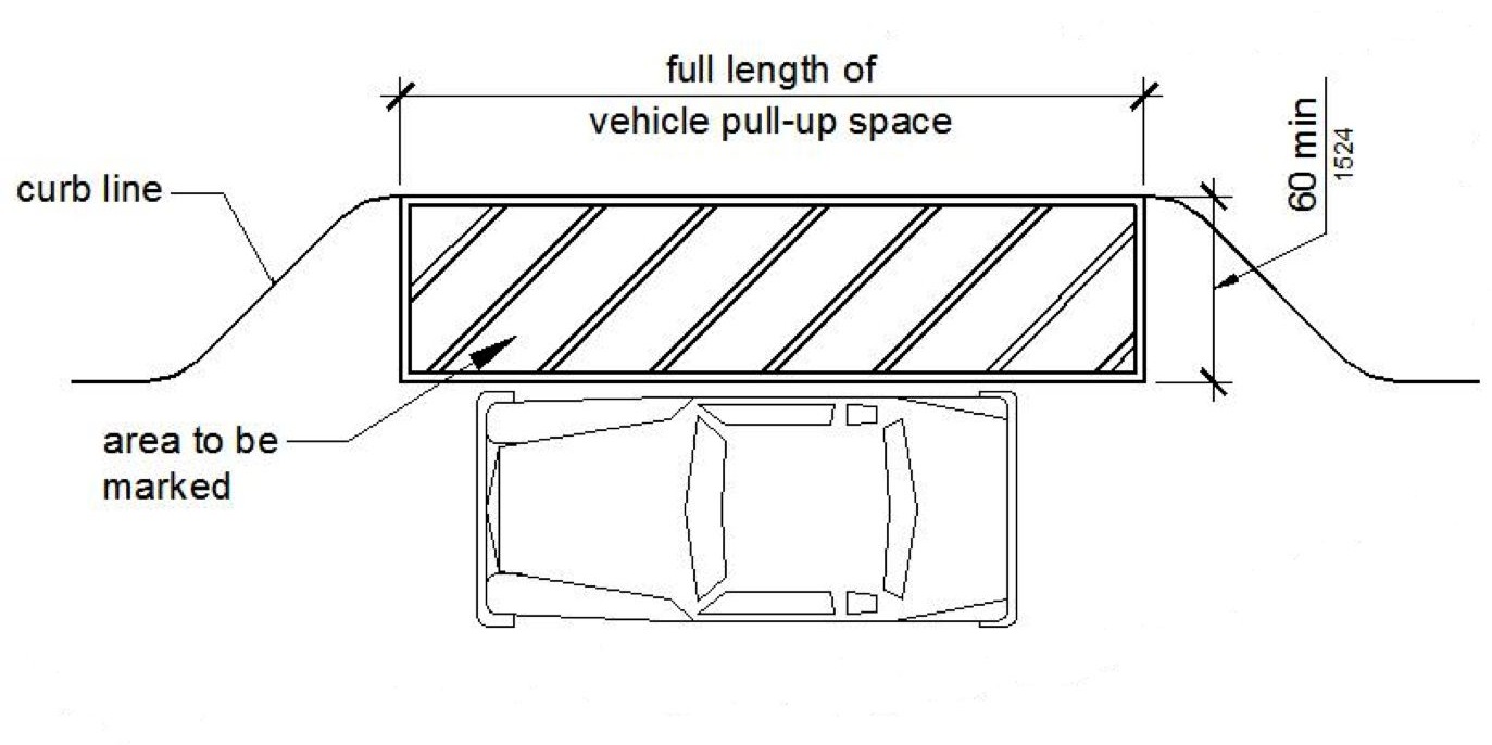
PASSENGER DROP-OFF AND LOADING ZONE ACCESS AISLE
11B-503.4 Floor and ground surfaces.
Vehicle pull-up spaces and access aisles serving them shall comply with Section 11B-302. Access aisles shall be at the same level as the vehicle pull-up space they serve. Changes in level are not permitted.
Exception: Slopes not steeper than 1:48 shall be permitted
11B-503.5 Vertical clearance.
Vehicle pull-up spaces, access aisles serving them, and a vehicular route from an entrance to the passenger loading zone and from the passenger loading zone to a vehicular exit shall provide a vertical clearance of 114 inches (2896 mm) minimum.

11B-503.6 Identification.
Each passenger loading zone designated for persons with disabilities shall be identified with a reflectorized sign complying with Section 11B-703.5. It shall be permanently posted immediately adjacent to and visible from the passenger loading zone stating “Passenger Loading Zone Only” and including the International Symbol of Accessibility complying with Section 11B-703.7.2.1 in white on a dark blue background.
11B-504.2 Treads and risers.
All steps on a flight of stairs shall have uniform riser heights and uniform tread depths. Risers shall be 4 inches (102 mm) high minimum and 7 inches (178 mm) high maximum. Treads shall be 11 inches (279 mm) deep minimum.
Exception: Curved stairways with winder treads are permitted at stairs which are not part of a required means of egress.
11B-504.3 Open risers.
Open risers are not permitted.
Exceptions:
1. On exterior stairways, an opening of not more than ½ inch (12.7 mm) may be permitted between the base of the riser and the tread.
2. On exterior stairways, risers constructed of grating containing openings of not more than ½ inch (12.7 mm) may be permitted.
11B-504.4 Tread surface.
Stair treads shall comply with Section 11B-302. Changes in level are not permitted.
Exception: Treads shall be permitted to have a slope not steeper than 1:48.
11B-504.4.1 Contrasting stripe.
Interior stairs shall have the upper approach and lower tread marked by a stripe providing clear visual contrast. Exterior stairs shall have the upper approach and all treads marked by a stripe providing clear visual contrast.
The stripe shall be a minimum of 2 inches (51 mm) wide to a maximum of 4 inches (102 mm) wide placed parallel to, and not more than 1 inch (25 mm) from, the nose of the step or upper approach. The stripe shall extend the full width of the step or upper approach and shall be of material that is at least as slip resistant as the other treads of the stair. A painted stripe shall be acceptable. Grooves shall not be used to satisfy this requirement.

ETA Editor's Note
The 2013 CBC 11B-504.4.1 requirement for contrasting stripes is not included in 2010 ADAS.
11B-504.5 Nosings.
The radius of curvature at the leading edge of the tread shall be ½ inch (12.7 mm) maximum. Nosings that project beyond risers shall have the underside of the leading edge curved or beveled. Risers shall be permitted to slope under the tread at an angle of 30 degrees maximum from vertical. The permitted projection of the nosing shall extend 1¼ inches (32 mm) maximum over the tread below.
Exception: In existing buildings there is no requirement to retroactively alter existing nosing projections of 1½ inches (38 mm) which were constructed in compliance with the building code in effect at the time of original construction.

Additionally, because it is possible to catch the top of one’s shoe on the underside of stair nosings, access compliance regulations require the underside of nosings to be free of abrupt changes – a beveled slope or non-square underside.◼
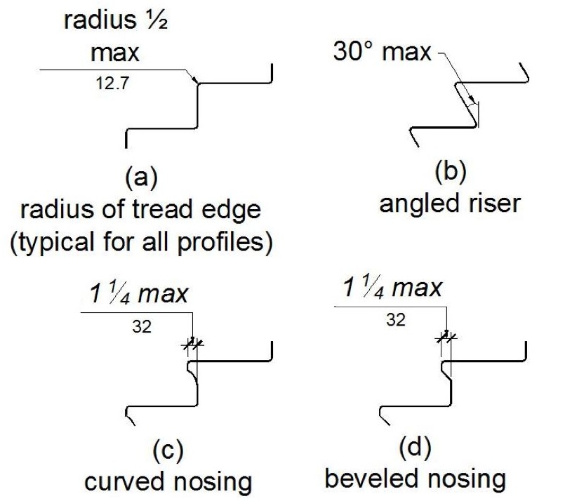
STAIR NOSINGS
11B-504.7 Wet conditions.
Stair treads and landings subject to wet conditions shall be designed to prevent the accumulation of water.
11B-504.8 Floor identification.
Floor identification signs required by Chapter 10, Section 1022.9 complying with Sections 11B-703.1, 11B-703.2 _|Raised Characters|_, 11B-703.3 _|Braille|_ and 11B-703.5 _|Visual Characters|_ shall be located at the landing of each floor level, placed adjacent to the door on the latch side, in all enclosed stairways in buildings two or more stories in height to identify the floor level. At the exit discharge level, the sign shall include a raised five pointed star located to the left of the identifying floor level. The outside diameter of the star shall be the same as the height of the raised characters.
ETA Editor's Note
Stairway signage is among the most frequently-observed barriers in California, because of the prevalent misunderstanding of the requirements. The "Floor Identification Signs" referenced in 2013 CBC 11B-504.8 and in the second paragraph (only) of 1022.9 should not be confused with the "Stairway Identification Signs" (hereinafter termed the "Fire Department Signs," to assist in clarifying) referenced in the first paragraph of 1022.9, and in 1022.9.1.
"Floor Identification Signs" are for routine wayfinding use by vision-impaired persons and others who use the stairs, and these are required at all enclosed stairways of multi-story buildings. They must be tactile, and located at the latch side of the door inside the stairway as prescribed by 2013 CBC Section 11B-703.4.
"Fire Department Signs" are for use by emergency responders, to enable efficient navigation through tall buildings in emergency situations without having to backtrack, losing valuable time. They are required at enclosed stairs in buildings with more than 3 stories above or below the level of exit discharge. They are not required to be, and should not be tactile. They are not required to be, and should not be located adjacent to the latch side of the door. Making them tactile and placing them at the latch side of the door does not benefit emergency responders, and distracts routine vision-impaired stair users by providing information that is of little wayfinding use (e.g., whether the stair connects to the roof level).
It is not possible to meet the requirements for both the "Floor Identification Signs" and the "Fire Department Signs" with a single sign at each stair level, although this is frequently observed. Architects, Signage Consultants and Manufacturers having standard details showing one sign for both purposes are encouraged to change them permanently, indicating two separate and distinct signs. The requirements of 11B-504.8 do not apply to the "Fire Department Signs."
Neither the "Floor Identification Signs" nor the "Fire Department Signs" are required by 2010 ADAS. Note also that neither of these signs is required at open stairways.
11B-505.1 General.
Handrails provided along walking surfaces complying with Section 11B-403, required at ramps complying with Section 11B-405, and required at stairs complying with Section 11B-504 shall comply with Section 11B-505.
11B-505.2 Where required.
Handrails shall be provided on both sides of stairs and ramps.
Exceptions:
1. In assembly areas, handrails shall not be required on both sides of aisle ramps where a handrail is provided at either side or within the aisle width.
2. Curb ramps do not require handrails.
3. At door landings, handrails are not required when the ramp run is less than 6 inches (152 mm) in rise or 72 inches (1829 mm) in length.
11B-505.3 Continuity.
Handrails shall be continuous within the full length of each stair flight or ramp run. Inside handrails on switchback or dogleg stairs and ramps shall be continuous between flights or runs.
Exception: In assembly areas, ramp handrails adjacent to seating or within the aisle width shall not be required to be continuous in aisles serving seating.
[2010 ADAS] EXCEPTION: In assembly areas, handrails on ramps shall not be required to be continuous in aisles serving seating.
11B-505.4 Height.
Top of gripping surfaces of handrails shall be 34 inches (864 mm) minimum and 38 inches (965 mm) maximum vertically above walking surfaces, stair nosings, and ramp surfaces. Handrails shall be at a consistent height above walking surfaces, stair nosings, and ramp surfaces.
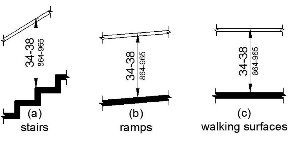
HANDRAIL HEIGHT
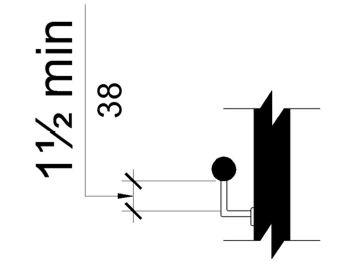
11B-505.5 Clearance.
Clearance between handrail gripping surfaces and adjacent surfaces shall be 1½ inches (38 mm) minimum. Handrails may be located in a recess if the recess is 3 inches (76 mm) maximum deep and 18 inches (457 mm) minimum clear above the top of the handrail.
[2010 ADAS] 505.5 Clearance. Clearance between handrail gripping surfaces and adjacent surfaces shall be 1½ inches (38 mm) minimum.
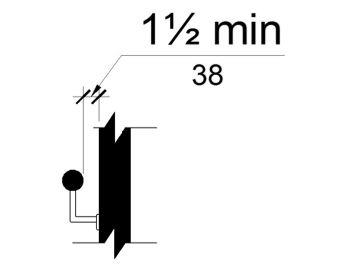
HANDRAIL CLEARANCE
11B-505.6 Gripping surface.
Handrail gripping surfaces shall be continuous along their length and shall not be obstructed along their tops or sides. The bottoms of handrail gripping surfaces shall not be obstructed for more than 20 percent of their length. Where provided, horizontal projections shall occur 1½ inches (38 mm) minimum below the bottom of the handrail gripping surface.
Exceptions:
1. Where handrails are provided along walking surfaces with slopes not steeper than 1:20, the bottoms of handrail gripping surfaces shall be permitted to be obstructed along their entire length where they are integral to crash rails or bumper guards.
2. The distance between horizontal projections and the bottom of the gripping surface shall be permitted to be reduced by 1/8 inch (3.2 mm) for each ½ inch (12.7 mm) of additional handrail perimeter dimension that exceeds 4 inches (102 mm).
HORIZONTAL PROJECTIONS BELOW GRIPPING SURFACE
11B-505.7 Cross section.
Handrail gripping surfaces shall have a cross section complying with Section 11B-505.7.1 or 11B-505.7.2.
11B-505.7.1 Circular cross section.
Handrail gripping surfaces with a circular cross section shall have an outside diameter of 1¼ inches (32 mm) minimum and 2 inches (51 mm) maximum.
11B-505.7.2 Non-circular cross sections.
Handrail gripping surfaces with a non-circular cross section shall have a perimeter dimension of 4 inches (102 mm) minimum and 6¼ inches (159 mm) maximum, and a cross-section dimension of 2¼ inches (57 mm) maximum.
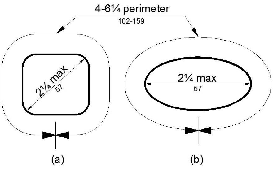
HANDRAIL NON-CIRCULAR CROSS SECTION
11B-505.8 Surfaces.
Handrail gripping surfaces and any surfaces adjacent to them shall be free of sharp or abrasive elements and shall have rounded edges.
11B-505.9 Fittings.
Handrails shall not rotate within their fittings.
11B-505.10 Handrail extensions.
Handrail gripping surfaces shall extend beyond and in the same direction of stair flights and ramp runs in accordance with Section 11B-505.10.
Exceptions:
1. Extensions shall not be required for continuous handrails at the inside turn of switchback or dogleg stairs and ramps.
2. In assembly areas, extensions shall not be required for ramp handrails in aisles serving seating where the handrails are discontinuous to provide access to seating and to permit crossovers within aisles.
3. In alterations, where the extension of the handrail in the direction of stair flight or ramp run would create a hazard, the extension of the handrail may be turned 90 degrees from the direction of stair flight or ramp run.
[2010 ADAS] 3. In alterations, full extensions of handrails shall not be required where such extensions would be hazardous due to plan configuration.
ETA Editor's Note
The 2013 CBC 11B-505.10 Exception 3 is more stringent than 2010 ADAS, which allows the handrail extensions to be eliminated in alterations where they would be hazardous. Handrail extensions are never permitted to turn 90 degrees at new stairs or new ramps, either by CBC or ADAS, except at continuous inside handrails (per Exception 1).
11B-505.10.1 Top and bottom extension at ramps.
Ramp handrails shall extend horizontally above the landing for 12 inches (305 mm) minimum beyond the top and bottom of ramp runs. Extensions shall return to a wall, guard, or the landing surface, or shall be continuous to the handrail of an adjacent ramp run.
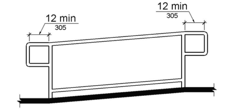
TOP AND BOTTOM HANDRAIL EXTENSION AT RAMPS
11B-505.10.2 Top extension at stairs.
At the top of a stair flight, handrails shall extend horizontally above the landing for 12 inches (305 mm) minimum beginning directly above the first riser nosing. Extensions shall return to a wall, guard, or the landing surface, or shall be continuous to the handrail of an adjacent stair flight.
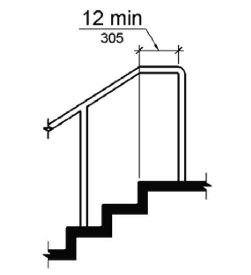
TOP HANDRAIL EXTENSION AT STAIRS
11B-505.10.3 Bottom extension at stairs.
At the bottom of a stair flight, handrails shall extend at the slope of the stair flight for a horizontal distance equal to one tread depth beyond the last riser nosing. The horizontal extension of a handrail shall be 12 inches (305 mm) long minimum and a height equal to that of the sloping portion of the handrail as measured above the stair nosings. Extension shall return to a wall, guard, or the landing surface, or shall be continuous to the handrail of an adjacent stair flight.
[2010 ADAS] 505.10.3 Bottom Extension at Stairs. At the bottom of a stair flight, handrails shall extend at the slope of the stair flight for a horizontal distance at least equal to one tread depth beyond the last riser nosing. Extension shall return to a wall, guard, or the landing surface, or shall be continuous to the handrail of an adjacent stair flight.
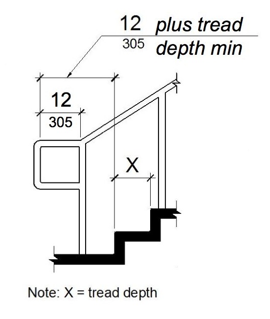
BOTTOM HANDRAIL EXTENSION AT STAIRS
User Comments/Questions
Add Comment/Question