APPENDIX
This appendix contains materials of an advisory nature and provides additional information that should help the reader to understand the minimum requirements of the guidelines or to design buildings or facilities for greater accessibility. The paragraph numbers correspond to the sections or paragraphs of the guideline to which the material relates and are therefore not consecutive (for example, A4.2.1 contains additional information relevant to 4.2.1). Sections of the guidelines for which additional material appears in this appendix have been indicated by an asterisk. Nothing in this appendix shall in any way obviate any obligation to comply with the requirements of the guidelines itself.
A2.2 Equivalent Facilitation.
Specific examples of equivalent facilitation are found in the following sections:
| 4.1.6(3)(c) | Elevators in Alterations |
| 4.31.9 | Text Telephones |
| 7.2 | Sales and Service Counters, Teller Windows, Information Counters |
| 9.1.4 | Classes of Sleeping Accommodations |
| 9.2.2(6)(d) | Requirements for Accessible Units, Sleeping Rooms, and Suites |
A4.1.1(3) Areas Used Only by Employees as Work Areas.
Where there are a series of individual work stations of the same type (e.g., laboratories, service counters, ticket booths), 5%, but not less than one, of each type of work station should be constructed so that an individual with disabilities can maneuver within the work stations. Rooms housing individual offices in a typical office building must meet the requirements of the guidelines concerning doors, accessible routes, etc. but do not need to allow for maneuvering space around individual desks. Modifications required to permit maneuvering within the work area may be accomplished as a reasonable accommodation to individual employees with disabilities under Title I of the ADA. Consideration should also be given to placing shelves in employee work areas at a convenient height for accessibility or installing commercially available shelving that is adjustable so that reasonable accommodations can be made in the future.
If work stations are made accessible they should comply with the applicable provisions of 4.2 through 4.35.
A4.1.2(5)(e) Valet Parking.
Valet parking is not always usable by individuals with disabilities. For instance, an individual may use a type of vehicle controls that render the regular controls inoperable or the driver’s seat in a van may be removed. In these situations, another person cannot park the vehicle. It is recommended that some self-parking spaces be provided at valet parking facilities for individuals whose vehicles cannot be parked by another person and that such spaces be located on an accessible route to the entrance of the facility.
A4.1.3(5) Only full passenger elevators are covered by the accessibility provisions of 4.10. Materials and equipment hoists, freight elevators not intended for passenger use, dumbwaiters, and construction elevators are not covered by these guidelines. If a building is exempt from the elevator requirement, it is not necessary to provide a platform lift or other means of vertical access in lieu of an elevator.
Under Exception 4, platform lifts are allowed where existing conditions make it impractical to install a ramp or elevator. Such conditions generally occur where it is essential to provide access to small raised or lowered areas where space may not be available for a ramp. Examples include, but are not limited to, raised pharmacy platforms, commercial offices raised above a sales floor, or radio and news booths.
A4.1.3(9) Supervised automatic sprinkler systems have built in signals for monitoring features of the system such as the opening and closing of water control valves, the power supplies for needed pumps, water tank levels, and for indicating conditions that will impair the satisfactory operation of the sprinkler system. Because of these monitoring features, supervised automatic sprinkler systems have a high level of satisfactory performance and response to fire conditions.
A4.1.3(10) If an odd number of drinking fountains is provided on a floor, the requirement in 4.1.3(10)(b) may be met by rounding down the odd number to an even number and calculating 50% of the even number. When more than one drinking fountain on a floor is required to comply with 4.15, those fountains should be dispersed to allow wheelchair users convenient access. For example, in a large facility such as a convention center that has water fountains at several locations on a floor, the accessible water fountains should be located so that wheelchair users do not have to travel a greater distance than other people to use a drinking fountain.
A4.1.3(17)(b) In addition to the requirements of section 4.1.3(17)(b), the installation of additional volume controls is encouraged. Volume controls may be installed on any telephone.
A4.1.3(19)(a) Readily removable or folding seating units may be installed in lieu of providing an open space for wheelchair users. Folding seating units are usually two fixed seats that can be easily folded into a fixed center bar to allow for one or two open spaces for wheelchair users when necessary. These units are more easily adapted than removable seats which generally require the seat to be removed in advance by the facility management.
Either a sign or a marker placed on seating with removable or folding arm rests is required by this section. Consideration should be given for ensuring identification of such seats in a darkened theater. For example, a marker which contrasts (light on dark or dark on light) and which also reflects light could be placed on the side of such seating so as to be visible in a lighted auditorium and also to reflect light from a flashlight.
A4.1.6(1)(h) When an entrance is being altered, it is preferable that those entrances being altered be made accessible to the extent feasible.
(1) Space Requirements for Wheelchairs. Many persons who use wheelchairs need a 30 in (760 mm) clear opening width for doorways, gates, and the like, when the latter are entered head-on. If the person is unfamiliar with a building, if competing traffic is heavy, if sudden or frequent movements are needed, or if the wheelchair must be turned at an opening, then greater clear widths are needed. For most situations, the addition of an inch of leeway on either side is sufficient. Thus, a minimum clear width of 32 in (815 mm) will provide adequate clearance. However, when an opening or a restriction in a passageway is more than 24 in (610 mm) long, it is essentially a passageway and must be at least 36 in (915 mm) wide.
(2) Space Requirements for Use of Walking Aids. Although people who use walking aids can maneuver through clear width openings of 32 in (815 mm), they need 36 in (915 mm) wide passageways and walks for comfortable gaits. Crutch tips, often extending down at a wide angle, are a hazard in narrow passageways where they might not be seen by other pedestrians. Thus, the 36 in (915 mm) width provides a safety allowance both for the person with a disability and for others.
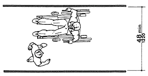
(3) Space Requirements for Passing. Able-bodied persons in winter clothing, walking straight ahead with arms swinging, need 32 in (815 mm) of width, which includes 2 in (50 mm) on either side for sway, and another 1 in (25 mm) tolerance on either side for clearing nearby objects or other pedestrians. Almost all wheelchair users and those who use walking aids can also manage within this 32 in (815 mm) width for short distances. Thus, two streams of traffic can pass in 64 in (1625 mm) in a comfortable flow. Sixty inches (1525 mm) provides a minimum width for a somewhat more restricted flow. If the clear width is less than 60 in (1525 mm), two wheelchair users will not be able to pass but will have to seek a wider place for passing. Forty-eight inches (1220 mm) is the minimum width needed for an ambulatory person to pass a nonambulatory [sic] or semi-ambulatory person. Within this 48 in (1220 mm) width, the ambulatory person will have to twist to pass a wheelchair user, a person with a service animal, or a semi-ambulatory person. There will be little leeway for swaying or missteps (see Fig. A1).
Fig. A1 Minimum Passage Width for One Wheelchair and One Ambulatory Person
A4.2.3 Wheelchair Turning Space.
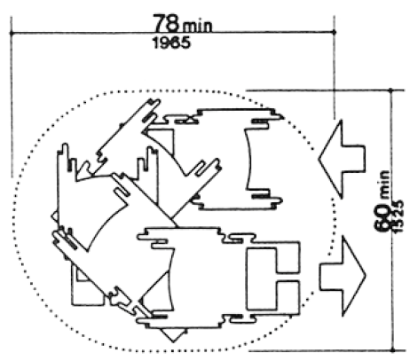
These guidelines specify a minimum space of 60 in (1525 mm) diameter or a 60 in by 60 in (1525 mm by 1525 mm) T-shaped space for a pivoting 180-degree turn of a wheelchair. This space is usually satisfactory for turning around, but many people will not be able to turn without repeated tries and bumping into surrounding objects. The space shown in Fig. A2 will allow most wheelchair users to complete U-turns without difficulty.
Fig. A2 Space Needed for Smooth U-Turn in a Wheelchair
A4.2.4 Clear Floor or Ground Space for Wheelchairs.
The wheelchair and user shown in Fig. A3 represent typical dimensions for a large adult male. The space requirements in this guideline are based upon maneuvering clearances that will accommodate most wheelchairs. Fig. A3 provides a uniform reference for design not covered by this guideline.
Fig. A3 Dimensions of Adult-Sized Wheelchairs
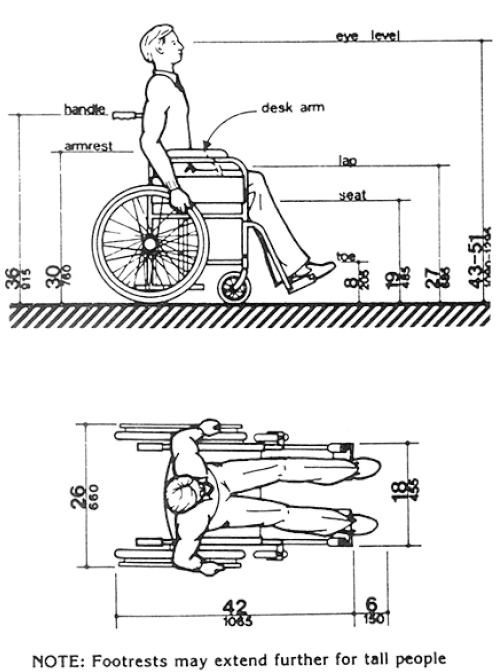
Fig. A3 (a)

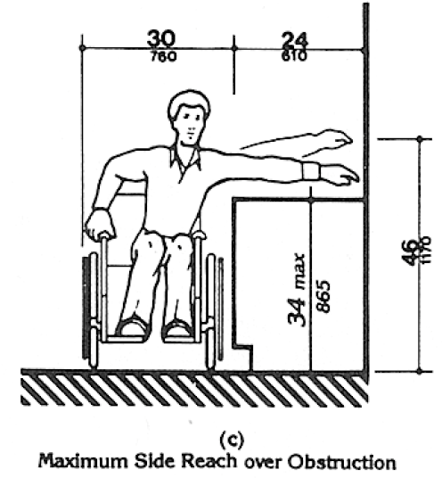
A4.2.5 & A4.2.6 Reach.
Reach ranges for persons seated in wheelchairs may be further clarified by Fig. A3(a). These drawings approximate in the plan view the information shown in Fig. 4, 5, and 6.
Fig. A3 (a)
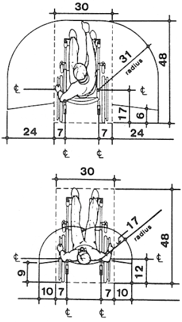
Fig. 4 Minimum Clear Floor Space for Wheelchairs
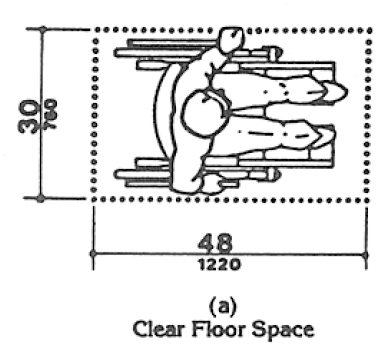
Fig. 4 Minimum Clear Floor Space for Wheelchairs
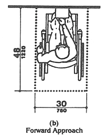
Fig. 4 Minimum Clear Floor Space for Wheelchairs
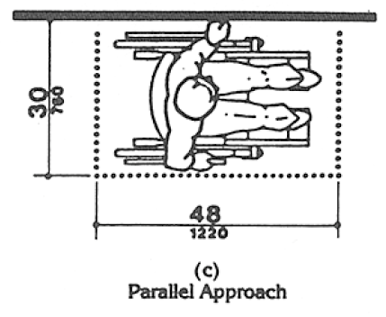
Fig. 4 Minimum Clear Floor Space for Wheelchairs
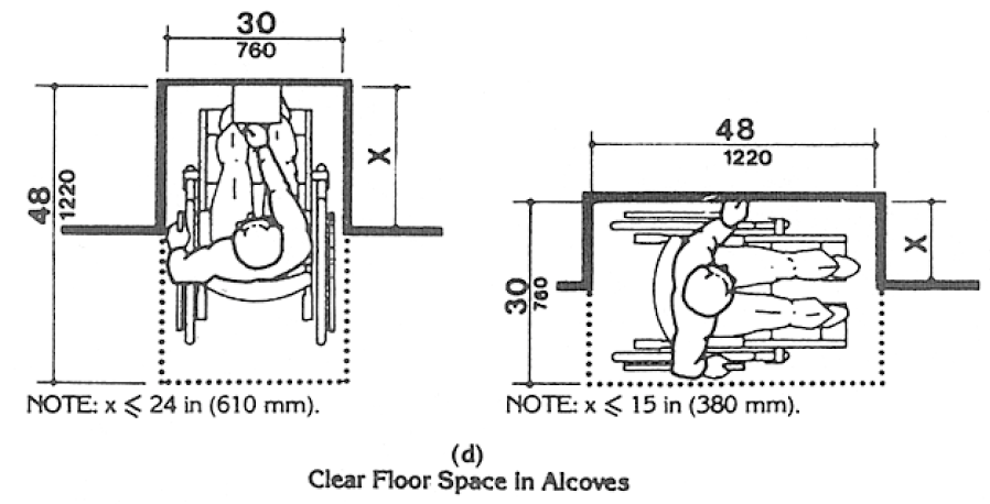
Fig. 4 Minimum Clear Floor Space for Wheelchairs
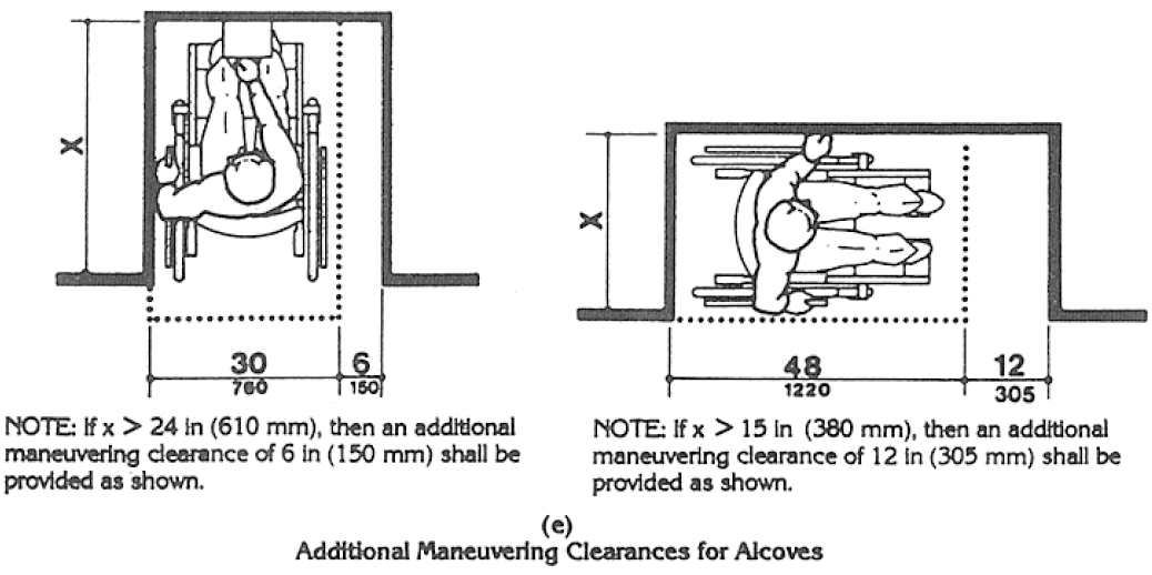
Fig. 5 Forward Reach
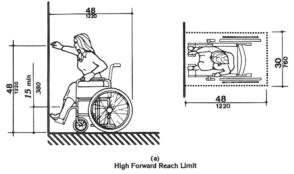
Fig. 5 Forward Reach
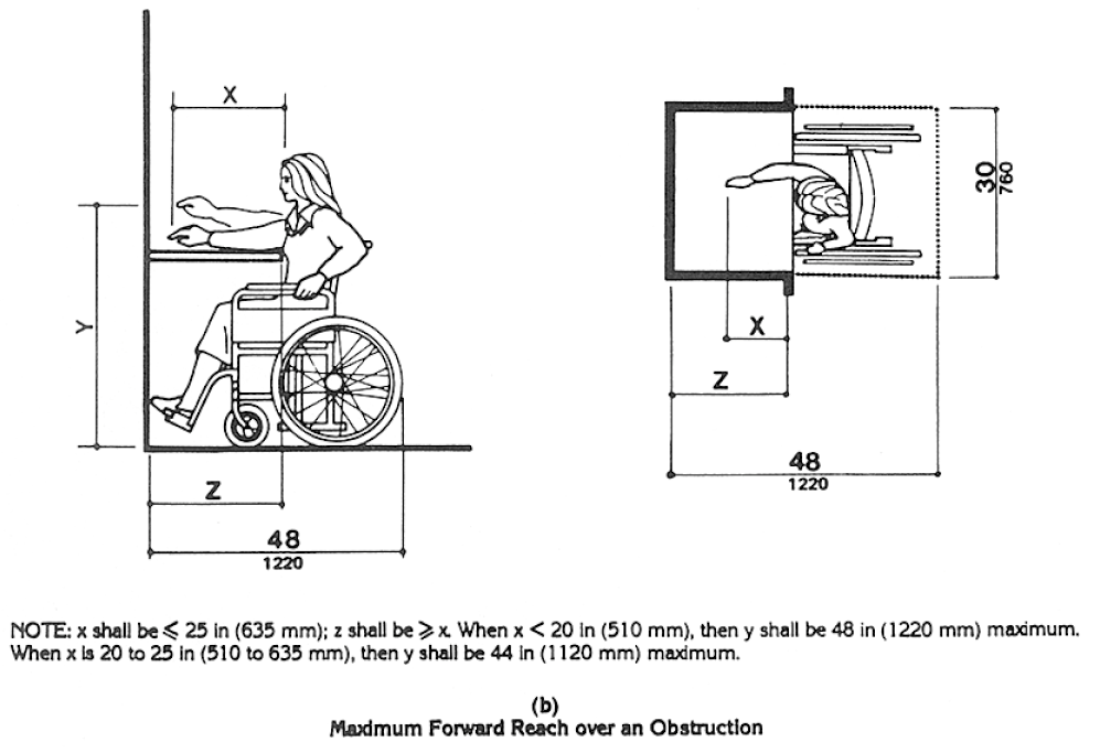
Fig. 6 Side Reach
Fig. 6 Side Reach
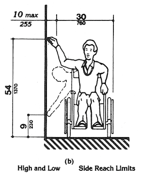
Fig. 6 Side Reach
(1) Travel Distances. Many people with mobility impairments can move at only very slow speeds; for many, traveling 200 ft (61 m) could take about 2 minutes. This assumes a rate of about 1.5 ft/s (455 mm/s) on level ground. It also assumes that the traveler would move continuously. However, on trips over 100 ft (30 m), disabled people are apt to rest frequently, which substantially increases their trip times. Resting periods of 2 minutes for every 100 ft (30 m) can be used to estimate travel times for people with severely limited stamina. In inclement weather, slow progress and resting can greatly increase a disabled person’s exposure to the elements.
(2) Sites. Level, indirect routes or those with running slopes lower than 1:20 can sometimes provide more convenience than direct routes with maximum allowable slopes or with ramps.
A4.3.10 Egress.
Because people with disabilities may visit, be employed or be a resident in any building, emergency management plans with specific provisions to ensure their safe evacuation also play an essential role in fire safety and life safety.
A4.3.11.3 Stairway Width.
A 48 in (1220 mm) wide exit stairway is needed to allow assisted evacuation (e.g., carrying a person in a wheelchair) without encroaching on the exit path for ambulatory persons.
A4.3.11.4 Two-way Communication.
It is essential that emergency communication not be dependent on voice communications alone because the safety of people with hearing or speech impairments could be jeopardized. The visible signal requirement could be satisfied with something as simple as a button in the area of rescue assistance that lights, indicating that help is on the way, when the message is answered at the point of entry.
A4.4.1 General.
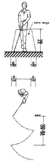
Service animals are trained to recognize and avoid hazards. However, most people with severe impairments of vision use the long cane as an aid to mobility. The two principal cane techniques are the touch technique, where the cane arcs from side to side and touches points outside both shoulders; and the diagonal technique, where the cane is held in a stationary position diagonally across the body with the cane tip touching or just above the ground at a point outside one shoulder and the handle or grip extending to a point outside the other shoulder. The touch technique is used primarily in uncontrolled areas, while the diagonal technique is used primarily in certain limited, controlled, and familiar environments. Cane users are often trained to use both techniques.
Potential hazardous objects are noticed only if they fall within the detection range of canes (see Fig. A4). Visually impaired people walking toward an object can detect an overhang if its lowest surface is not higher than 27 in (685 mm). When walking alongside protruding objects, they cannot detect overhangs. Since proper cane and service animal techniques keep people away from the edge of a path or from walls, a slight overhang of no more than 4 in (100 mm) is not hazardous.
Fig. A4 Cane Technique
A4.5.1 General.
People who have difficulty walking or maintaining balance or who use crutches, canes, or walkers, and those with restricted gaits are particularly sensitive to slipping and tripping hazards. For such people, a stable and regular surface is necessary for safe walking, particularly on stairs. Wheelchairs can be propelled most easily on surfaces that are hard, stable, and regular. Soft loose surfaces such as shag carpet, loose sand or gravel, wet clay, and irregular surfaces such as cobblestones can significantly impede wheelchair movement.
Slip resistance is based on the frictional force necessary to keep a shoe heel or crutch tip from slipping on a walking surface under conditions likely to be found on the surface. While the dynamic coefficient of friction during walking varies in a complex and non-uniform way, the static coefficient of friction, which can be measured in several ways, provides a close approximation of the slip resistance of a surface. Contrary to popular belief, some slippage is necessary to walking, especially for persons with restricted gaits; a truly “non-slip” surface could not be negotiated.
The Occupational Safety and Health Administration recommends that walking surfaces have a static coefficient of friction of 0.5. A research project sponsored by the Architectural and Transportation Barriers Compliance Board (Access Board) conducted tests with persons with disabilities and concluded that a higher coefficient of friction was needed by such persons. A static coefficient of friction of 0.6 is recommended for accessible routes and 0.8 for ramps.
It is recognized that the coefficient of friction varies considerably due to the presence of contaminants, water, floor finishes, and other factors not under the control of the designer or builder and not subject to design and construction guidelines and that compliance would be difficult to measure on the building site. Nevertheless, many common building materials suitable for flooring are now labeled with information on the static coefficient of friction. While it may not be possible to compare one product directly with another, or to guarantee a constant measure, builders and designers are encouraged to specify materials with appropriate values. As more products include information on slip resistance, improved uniformity in measurement and specification is likely. The Access Board’s advisory guidelines on Slip Resistant Surfaces provides additional information on this subject.
Cross slopes on walks and ground or floor surfaces can cause considerable difficulty in propelling a wheelchair in a straight line.
A4.5.3 Carpet.
Much more needs to be done in developing both quantitative and qualitative criteria for carpeting (i.e., problems associated with texture and weave need to be studied). However, certain functional characteristics are well established. When both carpet and padding are used, it is desirable to have minimum movement (preferably none) between the floor and the pad and the pad and the carpet which would allow the carpet to hump or warp. In heavily trafficked areas, a thick, soft (plush) pad or cushion, particularly in combination with long carpet pile, makes it difficult for individuals in wheelchairs and those with other ambulatory disabilities to get about. Firm carpeting can be achieved through proper selection and combination of pad and carpet, sometimes with the elimination of the pad or cushion, and with proper installation. Carpeting designed with a weave that causes a zig-zag effect when wheeled across is strongly discouraged.
A4.6.3 Parking Spaces.
The increasing use of vans with side-mounted lifts or ramps by persons with disabilities has necessitated some revisions in specifications for parking spaces and adjacent access aisles. The typical accessible parking space is 96 in (2440 mm) wide with an adjacent 60 in (1525 mm) access aisle. However, this aisle does not permit lifts or ramps to be deployed and still leave room for a person using a wheelchair or other mobility aid to exit the lift platform or ramp. In tests conducted with actual lift/van/wheelchair combinations, (under a Board-sponsored Accessible Parking and Loading Zones Project) researchers found that a space and aisle totaling almost 204 in (5180 mm) wide was needed to deploy a lift and exit conveniently. The “van accessible” parking space required by these guidelines provides a 96 in (2440 mm) wide space with a 96 in (2440 mm) adjacent access aisle which is just wide enough to maneuver and exit from a side mounted lift. If a 96 in (2440 mm) access aisle is placed between two spaces, two “van accessible” spaces are created. Alternatively, if the wide access aisle is provided at the end of a row (an area often unused), it may be possible to provide the wide access aisle without additional space (see Fig. A5(a)).
Fig. A5 Parking Space Alternatives
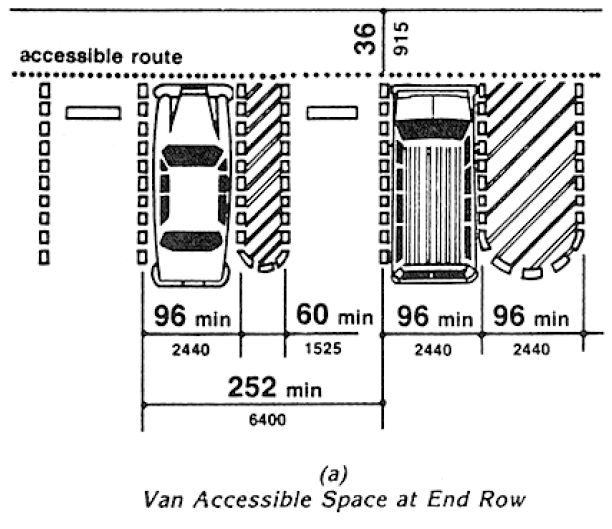
A sign is needed to alert van users to the presence of the wider aisle, but the space is not intended to be restricted only to vans.
“Universal” Parking Space Design. An alternative to the provision of a percentage of spaces with a wide aisle, and the associated need to include additional signage, is the use of what has been called the “universal” parking space design. Under this design, all accessible spaces are 132 in (3350 mm) wide with a 60 in (1525 mm) access aisle (see Fig. A5(b)). One advantage to this design is that no additional signage is needed because all spaces can accommodate a van with a side-mounted lift or ramp. Also, there is no competition between cars and vans for spaces since all spaces can accommodate either. Furthermore, the wider space permits vehicles to park to one side or the other within the 132 in (3350 mm) space to allow persons to exit and enter the vehicle on either the driver or passenger side, although, in some cases, this would require exiting or entering without a marked access aisle.
Fig. A5 Parking Space Alternatives
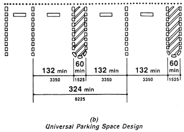
An essential consideration for any design is having the access aisle level with the parking space. Since a person with a disability, using a lift or ramp, must maneuver within the access aisle, the aisle cannot include a ramp or sloped area. The access aisle must be connected to an accessible route to the appropriate accessible entrance of a building or facility. The parking access aisle must either blend with the accessible route or have a curb ramp complying with 4.7. Such a curb ramp opening must be located within the access aisle boundaries, not within the parking space boundaries. Unfortunately, many facilities are designed with a ramp that is blocked when any vehicle parks in the accessible space. Also, the required dimensions of the access aisle cannot be restricted by planters, curbs or wheel stops.
A4.6.4 Signage.
Signs designating parking places for disabled people can be seen from a driver’s seat if the signs are mounted high enough above the ground and located at the front of a parking space.
A4.6.5 Vertical Clearance.
High-top vans, which disabled people or transportation services often use, require higher clearances in parking garages than automobiles.
A4.8.1 General.
Ramps are essential for wheelchair users if elevators or lifts are not available to connect different levels. However, some people who use walking aids have difficulty with ramps and prefer stairs.
A4.8.2 Slope and Rise.
Ramp slopes between 1:16 and 1:20 are preferred. The ability to manage an incline is related to both its slope and its length. Wheelchair users with disabilities affecting their arms or with low stamina have serious difficulty using inclines. Most ambulatory people and most people who use wheelchairs can manage a slope of 1:16. Many people cannot manage a slope of 1:12 for 30 ft (9 m).
A4.8.4 Landings.
Level landings are essential toward maintaining an aggregate slope that complies with these guidelines. A ramp landing that is not level causes individuals using wheelchairs to tip backward or bottom out when the ramp is approached.
A4.8.5 Handrails.
The requirements for stair and ramp handrails in this guideline are for adults. When children are principal users in a building or facility, a second set of handrails at an appropriate height can assist them and aid in preventing accidents.
A4.9.1 Minimum Number.
Only interior and exterior stairs connecting levels that are not connected by an elevator, ramp, or other accessible means of vertical access have to comply with 4.9.
A4.10.6 Door Protective and Reopening Device.
The required door reopening device would hold the door open for 20 seconds if the doorway remains obstructed. After 20 seconds, the door may begin to close. However, if designed in accordance with ASME A17.1‒1990, the door closing movement could still be stopped if a person or object exerts sufficient force at any point on the door edge.
A4.10.7 Door and Signal Timing for Hall Calls.
This paragraph allows variation in the location of call buttons, advance time for warning signals, and the door-holding period used to meet the time requirement.
A4.10.12 Car Controls.
Industry-wide standardization of elevator control panel design would make all elevators significantly more convenient for use by people with severe visual impairments. In many cases, it will be possible to locate the highest control on elevator panels within 48 in (1220 mm) from the floor.
A4.10.13 Car Position Indicators.
A special button may be provided that would activate the audible signal within the given elevator only for the desired trip, rather than maintaining the audible signal in constant operation.
A4.10.14 Emergency Communications.
A device that requires no handset is easier to use by people who have difficulty reaching. Also, small handles on handset compartment doors are not usable by people who have difficulty grasping.
Ideally, emergency two-way communication systems should provide both voice and visual display intercommunication so that persons with hearing impairments and persons with vision impairments can receive information regarding the status of a rescue. A voice intercommunication system cannot be the only means of communication because it is not accessible to people with speech and hearing impairments. While a voice intercommunication system is not required, at a minimum, the system should provide both an audio and visual indication that a rescue is on the way.
A4.11 Platform Lifts (Wheelchair Lifts).
A4.11.2 Other Requirements.
Inclined stairway chairlifts, and inclined and vertical platform lifts (wheelchair lifts) are available for short-distance, vertical transportation of people with disabilities. Care should be taken in selecting lifts as some lifts are not equally suitable for use by both wheelchair users and semi-ambulatory individuals.
A4.12.1 General.
Windows intended to be operated by occupants in accessible spaces should comply with 4.12.
A4.12.2 Window Hardware.
Windows requiring pushing, pulling, or lifting to open (for example, double-hung, sliding, or casement and awning units without cranks) should require no more than 5 lbf (22.2 N) to open or close. Locks, cranks, and other window hardware should comply with 4.27.
A4.13.8 Thresholds at Doorways.
Thresholds and surface height changes in doorways are particularly inconvenient for wheelchair users who also have low stamina or restrictions in arm movement because complex maneuvering is required to get over the level change while operating the door.
A4.13.9 Door Hardware.
Some disabled persons must push against a door with their chair or walker to open it. Applied kickplates on doors with closers can reduce required maintenance by withstanding abuse from wheelchairs and canes. To be effective, they should cover the door width, less approximately 2 in (51 mm), up to a height of 16 in (405 mm) from its bottom edge and be centered across the width of the door.
A4.13.10 Door Closers.
Closers with delayed action features give a person more time to maneuver through doorways. They are particularly useful on frequently used interior doors such as entrances to toilet rooms.
A4.13.11 Door Opening Force.
Although most people with disabilities can exert at least 5 lbf (22.2N), both pushing and pulling from a stationary position, a few people with severe disabilities cannot exert 3 lbf (13.13N). Although some people cannot manage the allowable forces in this guideline and many others have difficulty, door closers must have certain minimum closing forces to close doors satisfactorily. Forces for pushing or pulling doors open are measured with a push-pull scale under the following conditions:
(1) Hinged doors: Force applied perpendicular to the door at the door opener or 30 in (760 mm) from the hinged side, whichever is farther from the hinge.
(2) Sliding or folding doors: Force applied parallel to the door at the door pull or latch.
(3) Application of force: Apply force gradually so that the applied force does not exceed the resistance of the door. In high-rise buildings, air-pressure differentials may require a modification of this specification in order to meet the functional intent.
A4.13.12 Automatic Doors and Power-Assisted Doors.
Sliding automatic doors do not need guard rails and are more convenient for wheelchair users and visually impaired people to use. If slowly opening automatic doors can be reactivated before their closing cycle is completed, they will be more convenient in busy doorways.
A4.15.2 Spout Height.
Two drinking fountains, mounted side by side or on a single post, are usable by people with disabilities and people who find it difficult to bend over.
A4.16.3 Height.
Height preferences for toilet seats vary considerably among disabled people. Higher seat heights may be an advantage to some ambulatory disabled people, but are often a disadvantage for wheelchair users and others. Toilet seats 18 in (455 mm) high seem to be a reasonable compromise. Thick seats and filler rings are available to adapt standard fixtures to these requirements.
A4.16.4 Grab Bars.
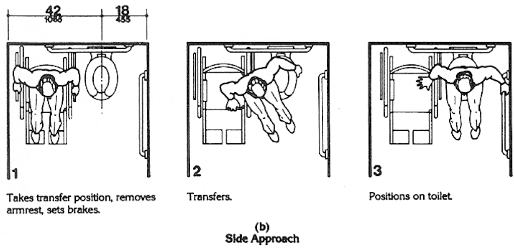
Fig. A6(a) and (b) show the diagonal and side approaches most commonly used to transfer from a wheelchair to a water closet. Some wheelchair users can transfer from the front of the toilet while others use a 90-degree approach. Most people who use the two additional approaches can also use either the diagonal approach or the side approach.
Fig. A6 Wheelchair Transfers

Fig. A6 Wheelchair Transfers
A4.16.5 Flush Controls.
Flush valves and related plumbing can be located behind walls or to the side of the toilet, or a toilet seat lid can be provided if plumbing fittings are directly behind the toilet seat. Such designs reduce the chance of injury and imbalance caused by leaning back against the fittings. Flush controls for tank-type toilets have a standardized mounting location on the left side of the tank (facing the tank). Tanks can be obtained by special order with controls mounted on the right side. If administrative authorities require flush controls for flush valves to be located in a position that conflicts with the location of the rear grab bar, then that bar may be split or shifted toward the wide side of the toilet area.
A4.17.3 Size and Arrangement.
This section requires use of the 60 in (1525 mm) standard stall (Figure 30(a)) and permits the 36 in (915 mm) or 48 in (1220 mm) wide alternate stall (Figure 30(b)) only in alterations where provision of the standard stall is technically infeasible or where local plumbing codes prohibit reduction in the number of fixtures. A standard stall provides a clear space on one side of the water closet to enable persons who use wheelchairs to perform a side or diagonal transfer from the wheelchair to the water closet. However, some persons with disabilities who use mobility aids such as walkers, canes or crutches are better able to use the two parallel grab bars in the 36 in (915 mm) wide alternate stall to achieve a standing position.
Fig. 30 Toilet Stalls
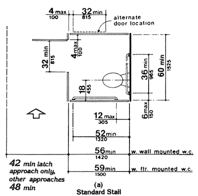
Fig. 30 Toilet Stalls
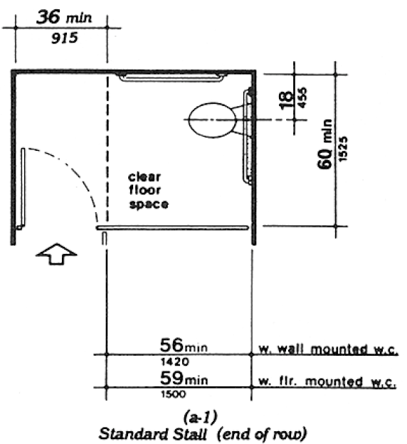
Fig. 30 Toilet Stalls
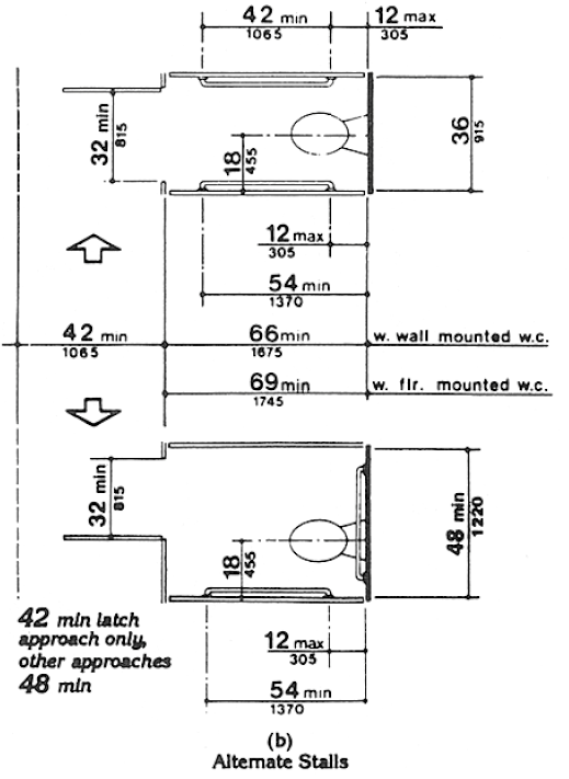
In large toilet rooms, where six or more toilet stalls are provided, it is therefore required that a 36 in (915 mm) wide stall with parallel grab bars be provided in addition to the standard stall required in new construction. The 36 in (915 mm) width is necessary to achieve proper use of the grab bars; wider stalls would position the grab bars too far apart to be easily used and narrower stalls would position the grab bars too close to the water closet. Since the stall is primarily intended for use by persons using canes, crutches and walkers, rather than wheelchairs, the length of the stall could be conventional. The door, however, must swing outward to ensure a usable space for people who use crutches or walkers.
A4.17.5 Doors.
To make it easier for wheelchair users to close toilet stall doors, doors can be provided with closers, spring hinges, or a pull bar mounted on the inside surface of the door near the hinge side.
A4.19.6 Mirrors.
If mirrors are to be used by both ambulatory people and wheelchair users, then they must be at least 74 in (1880 mm) high at their topmost edge. A single full length mirror can accommodate all people, including children.
A4.21.1 General.
Shower stalls that are 36 in by 36 in (915 mm by 915 mm) wide provide additional safety to people who have difficulty maintaining balance because all grab bars and walls are within easy reach. Seated people use the walls of 36 in by 36 in (915 mm by 915 mm) showers for back support. Shower stalls that are 60 in (1525 mm) wide and have no curb may increase usability of a bathroom by wheelchair users because the shower area provides additional maneuvering space.
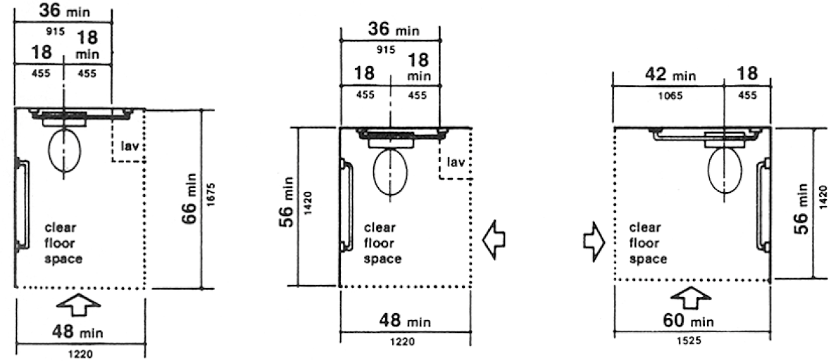
A4.22.3 Clear Floor Space.
In many small facilities, single-user restrooms may be the only facilities provided for all building users.
In addition, the guidelines allow the use of “unisex” or “family” accessible toilet rooms in alterations when technical infeasibility can be demonstrated. Experience has shown that the provision of accessible “unisex” or single-user restrooms is a reasonable way to provide access for wheelchair users and any attendants, especially when attendants are of the opposite sex. Since these facilities have proven so useful, it is often considered advantageous to install a “unisex” toilet room in new facilities in addition to making the multi-stall restrooms accessible, especially in shopping malls, large auditoriums, and convention centers.
Figure 28 (section 4.16) provides minimum clear floor space dimensions for toilets in accessible “unisex” toilet rooms. The dotted lines designate the minimum clear floor space, depending on the direction of approach, required for wheelchair users to transfer onto the water closet. The dimensions of 48 in (1220 mm) and 60 in (1525 mm), respectively, correspond to the space required for the two common transfer approaches utilized by wheelchair users (see Fig. A6). It is important to keep in mind that the placement of the lavatory to the immediate side of the water closet will preclude the side approach transfer illustrated in Figure A6(b).
Fig. A6 Wheelchair Transfers
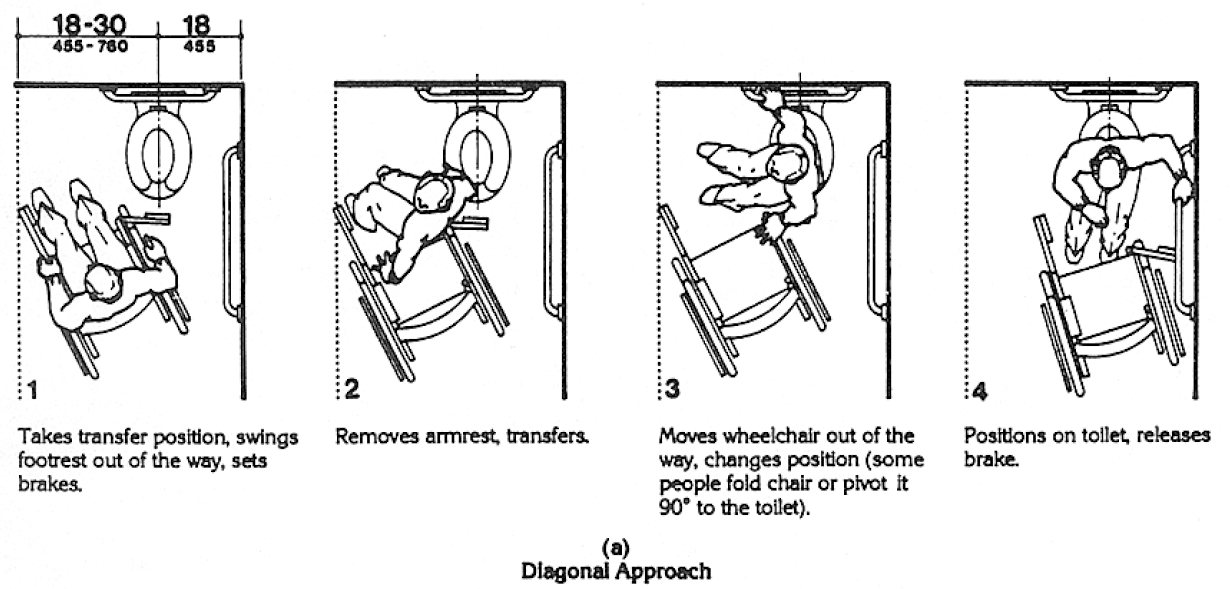
Fig. A6 Wheelchair Transfers

To accommodate the side transfer, the space adjacent to the water closet must remain clear of obstruction for 42 in (1065 mm) from the centerline of the toilet (Figure 28) and the lavatory must not be located within this clear space. A turning circle or T-turn, the clear floor space at the lavatory, and maneuvering space at the door must be considered when determining the possible wall locations. A privacy latch or other accessible means of ensuring privacy during use should be provided at the door.
RECOMMENDATIONS:
1. In new construction, accessible single-user restrooms may be desirable in some situations because they can accommodate a wide variety of building users. However, they cannot be used in lieu of making the multi-stall toilet rooms accessible as required.
2. Where strict compliance to the guidelines for accessible toilet facilities is technically infeasible in the alteration of existing facilities, accessible “unisex” toilets are a reasonable alternative.
3. In designing accessible single-user restrooms, the provisions of adequate space to allow a side transfer will provide accommodation to the largest number of wheelchair users.
Fig. 28 Clear Floor Space at Water Closets
A4.23.3 Clear Floor Space.
Figure A7 shows two possible configurations of a toilet room with a roll-in shower. The specific shower shown is designed to fit exactly within the dimensions of a standard bathtub. Since the shower does not have a lip, the floor space can be used for required maneuvering space. This would permit a toilet room to be smaller than would be permitted with a bathtub and still provide enough floor space to be considered accessible. This design can provide accessibility in facilities where space is at a premium (i.e., hotels and medical care facilities). The alternate roll-in shower (Fig. 57b) also provides sufficient room for the “T-turn” and does not require plumbing to be on more than one wall.
Fig. A7
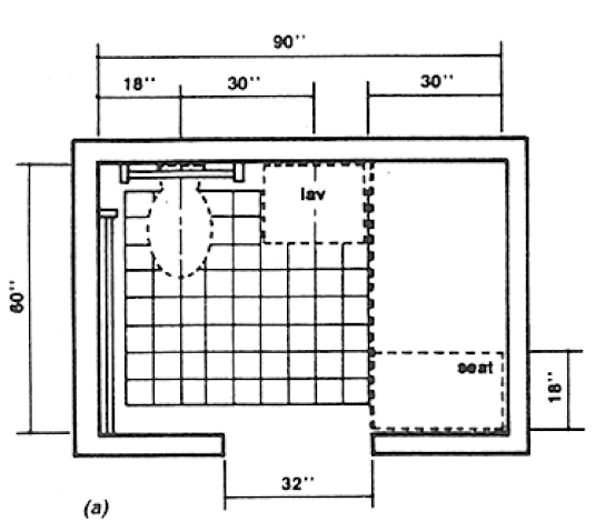
Fig. A7
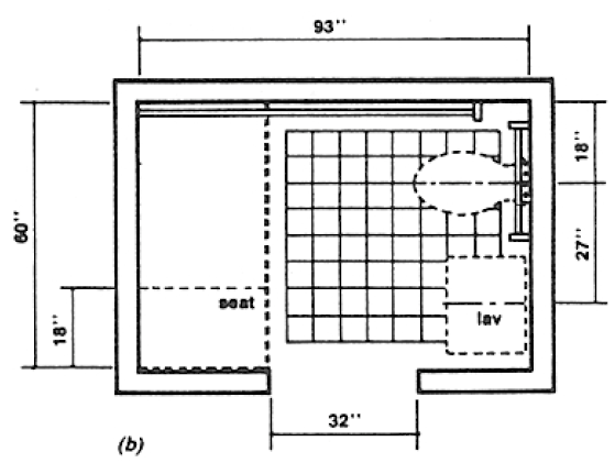
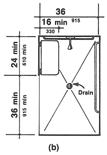
Fig. 57 Roll-in Shower with Folding Seat
A4.23.9 Medicine Cabinets.
Other alternatives for storing medical and personal care items are very useful to disabled people. Shelves, drawers, and floor-mounted cabinets can be provided within the reach ranges of disabled people.
A4.26.1 General.
Many disabled people rely heavily upon grab bars and handrails to maintain balance and prevent serious falls. Many people brace their forearms between supports and walls to give them more leverage and stability in maintaining balance or for lifting. The grab bar clearance of 1‒1/2 in (38 mm) required in this guideline is a safety clearance to prevent injuries resulting from arms slipping through the openings. It also provides adequate gripping room.
A4.26.2 Size and Spacing of Grab Bars and Handrails.
This specification allows for alternate shapes of handrails as long as they allow an opposing grip similar to that provided by a circular section of 1‒1/4 in to 1‒1/2 in (32 mm to 38 mm).
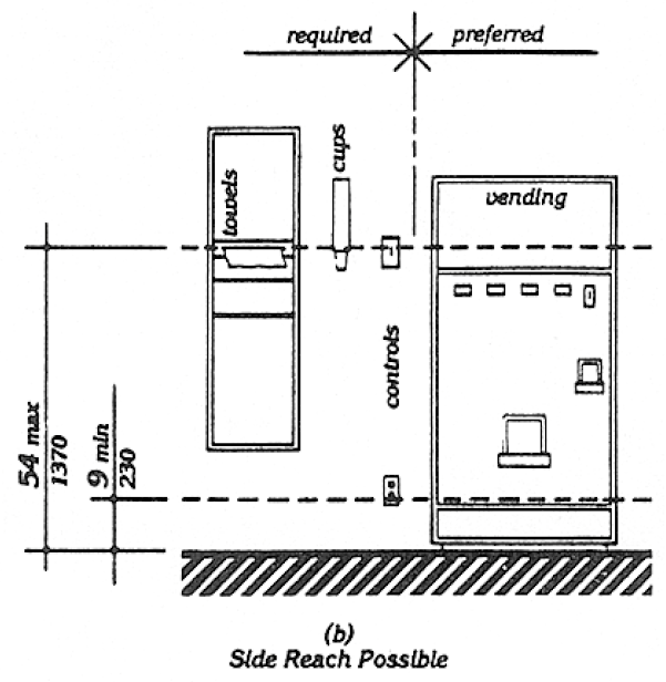
A4.27.3 Height.
Fig. A8 further illustrates mandatory and advisory control mounting height provisions for typical equipment.
Fig. A8 Control Reach Limitations
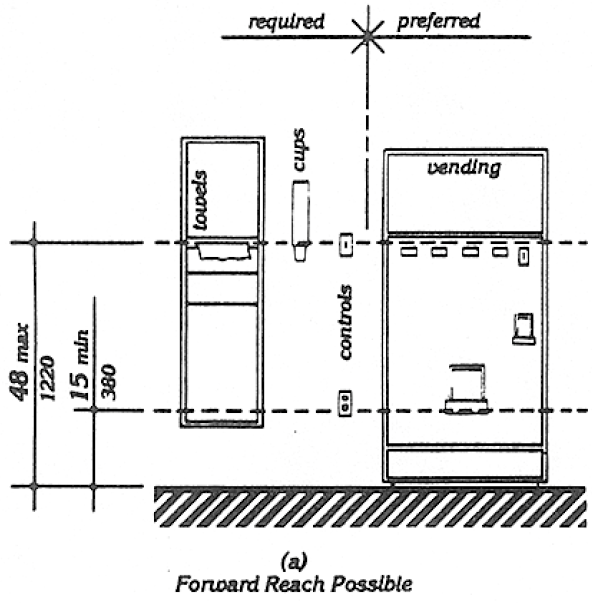
Fig. A8 Control Reach Limitations
Electrical receptacles installed to serve individual appliances and not intended for regular or frequent use by building occupants are not required to be mounted within the specified reach ranges. Examples would be receptacles installed specifically for wall-mounted clocks, refrigerators, and microwave ovens.
A4.28.2 Audible Alarms.
Audible emergency signals must have an intensity and frequency that can attract the attention of individuals who have partial hearing loss. People over 60 years of age generally have difficulty perceiving frequencies higher than 10,000 Hz. An alarm signal which has a periodic element to its signal, such as single stroke bells (clang-pause-clang-pause), hi-low (up-down-up-down) and fast whoop (on-off-on-off) are best. Avoid continuous or reverberating tones. Select a signal which has a sound characterized by three or four clear tones without a great deal of “noise” in between.
A4.28.3 Visual Alarms.
The specifications in this section do not preclude the use of zoned or coded alarm systems.
A4.28.4 Auxiliary Alarms.
Locating visual emergency alarms in rooms where persons who are deaf may work or reside alone can ensure that they will always be warned when an emergency alarm is activated. To be effective, such devices must be located and oriented so that they will spread signals and reflections throughout a space or raise the overall light level sharply. However, visual alarms alone are not necessarily the best means to alert sleepers. A study conducted by Underwriters Laboratory (UL) concluded that a flashing light more than seven times brighter was required (110 candela v. 15 candela, at the same distance) to awaken sleepers as was needed to alert awake subjects in a normal daytime illuminated room.
For hotel and other rooms where people are likely to be asleep, a signal-activated vibrator placed between mattress and box spring or under a pillow was found by UL to be much more effective in alerting sleepers. Many readily available devices are sound-activated so that they could respond to an alarm clock, clock radio, wake-up telephone call or room smoke detector. Activation by a building alarm system can either be accomplished by a separate circuit activating an auditory alarm which would, in turn, trigger the vibrator or by a signal transmitted through the ordinary 110-volt outlet. Transmission of signals through the power line is relatively simple and is the basis of common, inexpensive remote light control systems sold in many department and electronic stores for home use. So-called “wireless” intercoms operate on the same principal.
A4.29 Detectable Warnings.
A4.29.2 Detectable Warnings on Walking Surfaces. The material used to provide contrast should contrast by at least 70%. Contrast in percent is determined by:
Contrast = [(B1 - B2)/B1] x 100
where B1 = light reflectance value (LRV) of the lighter area and B2 = light reflectance value (LRV) of the darker area.
Note that in any application both white and black are never absolute; thus, B1 never equals 100 and B2 is always greater than 0.
A4.30.1 General.
In building complexes where finding locations independently on a routine basis may be a necessity (for example, college campuses), tactile maps or prerecorded instructions can be very helpful to visually impaired people. Several maps and auditory instructions have been developed and tested for specific applications. The type of map or instructions used must be based on the information to be communicated, which depends highly on the type of buildings or users.
Landmarks that can easily be distinguished by visually impaired individuals are useful as orientation cues. Such cues include changes in illumination level, bright colors, unique patterns, wall murals, location of special equipment or other architectural features.
Many people with disabilities have limitations in movement of their heads and reduced peripheral vision. Thus, signage positioned perpendicular to the path of travel is easiest for them to notice. People can generally distinguish signage within an angle of 30 degrees to either side of the centerlines of their faces without moving their heads.
A4.30.2 Character Proportion.
The legibility of printed characters is a function of the viewing distance, character height, the ratio of the stroke width to the height of the character, the contrast of color between character and background, and print font. The size of characters must be based upon the intended viewing distance. A severely nearsighted person may have to be much closer to recognize a character of a given size than a person with normal visual acuity.
A4.30.4 Raised and Brailled Characters and Pictorial Symbol Signs (Pictograms). The standard dimensions for literary Braille are as follows:
| Dot diameter | .059 in. |
| Inter-dot spacing | .090 in. |
|
Horizontal separation between cells |
.241 in. |
| Vertical separation between cells | .395 in. |
Raised borders around signs containing raised characters may make them confusing to read unless the border is set far away from the characters. Accessible signage with descriptive materials about public buildings, monuments, and objects of cultural interest may not provide sufficiently detailed and meaningful information. Interpretive guides, audio tape devices, or other methods may be more effective in presenting such information.
A4.30.5 Finish and Contrast.
An eggshell finish (11 to 19 degree gloss on 60 degree glossimeter) is recommended. Research indicates that signs are more legible for persons with low vision when characters contrast with their background by at least 70 percent. Contrast in percent shall be determined by:
Contrast = [(B1 - B2)/B1] x 100
where B1 = light reflectance value (LRV) of the lighter area and B2 = light reflectance value (LRV) of the darker area.
Note that in any application both white and black are never absolute; thus, B1 never equals 100 and B2 is always greater than 0.
The greatest readability is usually achieved through the use of light-colored characters or symbols on a dark background.
A4.30.7 Symbols of Accessibility for Different Types of Listening Systems.
Paragraph 4 of this section requires signage indicating the availability of an assistive listening system. An appropriate message should be displayed with the international symbol of access for hearing loss since this symbol conveys general accessibility for people with hearing loss. Some suggestions are:
INFRARED
ASSISTIVE LISTENING SYSTEM
AVAILABLE
----PLEASE ASK----
AUDIO LOOP IN USE
TURN T-SWITCH FOR
BETTER HEARING
----OR ASK FOR HELP----
FM
ASSISTIVE LISTENING
SYSTEM AVAILABLE
----PLEASE ASK----
The symbol may be used to notify persons of the availability of other auxiliary aids and services such as: real time captioning, captioned note taking, sign language interpreters, and oral interpreters.
A4.30.8 Illumination Levels.
Illumination levels on the sign surface shall be in the 100 to 300 lux range (10 to 30 footcandles) and shall be uniform over the sign surface. Signs shall be located such that the illumination level on the surface of the sign is not significantly exceeded by the ambient light or visible bright lighting source behind or in front of the sign.
A4.31.3 Mounting Height.
In localities where the dial-tone first system is in operation, calls can be placed at a coin telephone through the operator without inserting coins. The operator button is located at a height of 46 in (1170 mm) if the coin slot of the telephone is at 54 in (1370 mm). A generally available public telephone with a coin slot mounted lower on the equipment would allow universal installation of telephones at a height of 48 in (1220 mm) or less to all operable parts.
A4.31.9 Text Telephones.
A public text telephone may be an integrated text telephone pay phone unit or a conventional portable text telephone that is permanently affixed within, or adjacent to, the telephone enclosure. In order to be usable with a pay phone, a text telephone which is not a single integrated text telephone pay phone unit will require a shelf large enough (10 in (255mm) wide by 10 in (255 mm) deep with a 6 in (150 mm) vertical clearance minimum) to accommodate the device, an electrical outlet, and a power cord. Movable or portable text telephones may be used to provide equivalent facilitation. A text telephone should be readily available so that a person using it may access the text telephone easily and conveniently. As currently designed pocket-type text telephones for personal use do not accommodate a wide range of users. Such devices would not be considered substantially equivalent to conventional text telephones. However, in the future as technology develops this could change.
A4.32 Fixed or Built-in Seating and Tables.
A4.32.4 Height of Tables or Counters. Different types of work require different table or counter heights for comfort and optimal performance. Light detailed work such as writing requires a table or counter close to elbow height for a standing person. Heavy manual work such as rolling dough requires a counter or table height about 10 in (255 mm) below elbow height for a standing person. This principle of high/low table or counter heights also applies for seated persons; however, the limiting condition for seated manual work is clearance under the table or counter.
Table A1 shows convenient counter heights for seated persons. The great variety of heights for comfort and optimal performance indicates a need for alternatives or a compromise in height if people who stand and people who sit will be using the same counter area.
|
Conditions of Use |
Short Women in mm | Tall Men in mm |
|
Seated in a wheelchair: Manual work- Desk or removable armrests |
26 660 | 30 760 |
|
Fixed, full-size armrests2 |
323 815 | 323 815 |
|
Light, detailed work: Desk or removable armrests |
29 735 | 34 865 |
|
Fixed, full-size armrests2 |
323 815 | 34 865 |
|
Seated in a 16 in (405 mm) high chair: Manual work |
26 660 | 27 685 |
|
Light, detailed work |
28 710 | 31 785 |
1All dimensions are based on a work-surface thickness of 1 1/2 in (38 mm) and a clearance of 1 1/2 in (38 mm) between legs and the underside of a work surface.
2This type of wheelchair arm does not interfere with the positioning of a wheelchair under a work surface.
3This dimension is limited by the height of the armrests: a lower height would be preferable. Some people in this group prefer lower work surfaces, which require positioning the wheelchair back from the edge of the counter.
A4.33.2 Size of Wheelchair Locations.
Spaces large enough for two wheelchairs allow people who are coming to a performance together to sit together.
A4.33.3 Placement of Wheelchair Locations.
The location of wheelchair areas can be planned so that a variety of positions within the seating area are provided. This will allow choice in viewing and price categories.
Building/life safety codes set minimum distances between rows of fixed seats with consideration of the number of seats in a row, the exit aisle width and arrangement, and the location of exit doors. “Continental” seating, with a greater number of seats per row and a commensurate increase in row spacing and exit doors, facilitates emergency egress for all people and increases ease of access to mid-row seats especially for people who walk with difficulty. Consideration of this positive attribute of “continental” seating should be included along with all other factors in the design of fixed seating areas.
A4.33.6 Placement of Listening Systems.
A distance of 50 ft (15 m) allows a person to distinguish performers’ facial expressions.
A4.33.7 Types of Listening Systems.
An assistive listening system appropriate for an assembly area for a group of persons or where the specific individuals are not known in advance, such as a playhouse, lecture hall or movie theater, may be different from the system appropriate for a particular individual provided as an auxiliary aid or as part of a reasonable accommodation. The appropriate device for an individual is the type that individual can use, whereas the appropriate system for an assembly area will necessarily be geared toward the “average” or aggregate needs of various indi-viduals [sic]. A listening system that can be used from any seat in a seating area is the most flexible way to meet this specification. Earphone jacks with variable volume controls can benefit only people who have slight hearing loss and do not help people who use hearing aids. At the present time, magnetic induction loops are the most feasible type of listening system for people who use hearing aids equipped with “T-coils,” but people without hearing aids or those with hearing aids not equipped with inductive pick-ups cannot use them without special receivers. Radio frequency systems can be extremely effective and inexpensive. People without hearing aids can use them, but people with hearing aids need a special receiver to use them as they are presently designed. If hearing aids had a jack to allow a by-pass of microphones, then radio frequency systems would be suitable for people with and without hearing aids. Some listening systems may be subject to interference from other equipment and feedback from hearing aids of people who are using the systems. Such interference can be controll-ed [sic] by careful engineering design that anticipates feedback sources in the surrounding area.
Table A2, reprinted from a National Institute of Disability and Rehabilitation Research “Rehab Brief,” shows some of the advantages and disadvantages of different types of assistive listening systems. In addition, the Architectural and Transportation Barriers Compliance Board (Access Board) has published a pamphlet on Assistive Listening Systems which lists demonstration centers across the country where technical assistance can be obtained in selecting and installing appropriate systems. The state of New York has also adopted a detailed technical specification which may be useful.
Table A2. Summary of Assistive Listening Devices
| System | Advantages | Disadvantages | Typical Applications |
|
Induction Loop Transmitter: Transducer wired to induction loop around listening area. Receiver: Self-contained induction receiver or personal hearing aid with telecoil. |
Cost-Effective Low Maintenance Easy to use Unobtrusive May be possible to integrate into existing public address system. Some hearing aids can function as receivers. |
Signal spills over to adjacent rooms. Susceptible to electrical interference. Limited portability Inconsistent signal strength Head position affects signal strength. Lack of standards for induction coil performance. |
Meeting areas Theaters Churches and Temples Conference rooms Classrooms TV viewing |
|
FM Transmitter: Flashlight-sized worn by speaker. Receiver: With personal hearing aid via DAI or induction neck-loop and telecoil; or self-contained with earphone(s). |
Highly portable Different channels allow use by different groups within the same room. High user mobility Variable for large range of hearing losses. | High cost of receivers Equipment fragile Equipment obtrusive High maintenance Expensive to maintain Custom fitting to individual user may be required. | Classrooms Tour groups Meeting areas Outdoor events One-on-one |
| Infrared Transmitter: Emitter in line-of- sight with receiver. Receiver: Self-contained. Or with personal hearing aid via DAI or induction neckloop and telecoil. | Easy to use Insures privacy or confidentiality Moderate cost Can often be integrated into existing public address system. | Line-of-sight required between emitter and receiver. Ineffective outdoors Limited portability Requires installation | Theaters Churches and Temples Auditoriums Meetings requiring confidentiality TV viewing |
Source: Rehab Brief, National Institute on Disability and Rehabilitation Research, Washington, DC, Vol. XII, No. 10, (1990).
A5.1 General.
Dining counters (where there is no service) are typically found in small carry-out restaurants, bakeries, or coffee shops and may only be a narrow eating surface attached to a wall. This section requires that where such a dining counter is provided, a portion of the counter shall be at the required accessible height.
A7.2(3) Assistive Listening Devices.
At all sales and service counters, teller windows, box offices, and information kiosks where a physical barrier separates service personnel and customers, it is recommended that at least one permanently installed assistive listening device complying with 4.33 be provided at each location or series. Where assistive listening devices are installed, signage should be provided identifying those stations which are so equipped.
A7.3 Check-out Aisles.
Section 7.2 refers to counters without aisles; section 7.3 concerns check-out aisles. A counter without an aisle (7.2) can be approached from more than one direction such as in a convenience store. In order to use a check-out aisle (7.3), customers must enter a defined area (an aisle) at a particular point, pay for goods, and exit at a particular point.
A10.3.1(7) Route Signs.
One means of making control buttons on fare vending machines usable by persons with vision impairments is to raise them above the surrounding surface. Those activated by a mechanical motion are likely to be more detectable. If farecard vending, collection, and adjustment devices are designed to accommodate farecards having one tactually distinctive corner, then a person who has a vision impairment will insert the card with greater ease. Token collection devices that are designed to accommodate tokens which are perforated can allow a person to distinguish more readily between tokens and common coins. Thoughtful placement of accessible gates and fare vending machines in relation to inaccessible devices will make their use and detection easier for all persons with disabilities.
User Comments/Questions
Add Comment/Question