Recommendations on Standards for the Design of Medical Diagnostic Equipment for Adults with Disabilities, Advisory Committee Final Report
U.S. Access Board Medical Diagnostic Equipment
Mammography Subcommittee Report:
Final Recommendations on Equipment Criteria
Background: The most frequent type of cancer among women and the second leading cause of cancer-related deaths is breast cancer. A recent study published in the Journal of Women's Health, highlighted that women with disabilities may be less likely to receive a mammogram compared to women without a disability. Prevalence of self-reported mammography use is lower for women with disabilities (72.2% for women 40 years of age or older and 78.1% for women 50 to 74 years of age) than women without a disability (77.8% and 82.6%, respectively), refer to http://www.cdc.gov/features/breastcancerdisabilities/index.html.
Healthcare practitioners find breast-imaging challenging when patients must remain seated in mobility devices such as wheelchairs or scooters for the procedure. In order to obtain a quality image with the needed visualization of the breast tissue, a patient’s ability to approach and position next to the machine is vital. The key equipment barriers arise from the inherent conflict between the mobility device design and the mammography equipment design. The mammography device operation seems designed to require the patient has the ability to stand. Therefore, a woman using a wheelchair will experience two main barriers, the first is that her mobility device cannot get close enough to the mammography machine itself, and secondly, even if she does get close enough to the machine, the breast platform height does not lower enough to image a woman’s breasts while in the seated position.
The Mammography Subcommittee members provided varied expertise. Members included representation from disability advocates, healthcare organizations including technologists, industry designers, and engineers. Industry input provided supporting illustrations, which enhanced the discussion.
Overview: The subcommittee recognized that to get the best accessibility, equipment would need redesign to accommodate persons seated in wheeled mobility devices for the exam. In developing its proposals, the subcommittee considered the physical constraints needed for operation of the equipment, technical feasibility, patient safety, and clinical standards. The subcommittee weighed all the provisions for technical criteria in light of the equipment functionality and the need to image a range of body sizes, functionality, and types.
The subcommittee considered the interaction of mammography devices with individuals using scooter. Due to the need for the woman’s chest wall to be flush with the breast platform, the front scooter components make this position impossible without the person swiveling to the side. Thus, the final recommendations focused on the mammography device’s interaction with wheelchairs. Mammography equipment recommendations are also operable with use of a mammography chair for patients who need to sit for the procedure but do not use a wheelchair.
Mammography imaging involves complex interactions between moving parts. To get the final dimensions, the subcommittee needed to consider the elements “dynamically.” The dynamic angle is necessary because of the way the equipment operates. Recognizing that all operations center on the movable breast platform, recommendations define each component in relationship to the breast platform. The unique aspects of mammography device design and operation requires components to work when the breast platform is at breast height. Since breast platform design affects most of the other device components, defining each in relationship to the breast platform creates proportions that when incorporated into the design process assure that women in mobility devices can get effective imaging.
Ordinarily, the accessibility dimensions are static and measured from a static element such as the floor. Because of the movable breast platform and C-arm, each recommendation defines the other device components in relation to the breast platform. The static point is with the breast platform at the height of 34 inches. This allowed the subcommittee with industry input to consider and maximize the dimensions that improved the accessibility during the equipment’s operation. The result is that this report defines traditional accessibility elements from a different vantage point.
To determine the final criteria for the mammography devices, the subcommittee balanced the knowledge of disability, range of physical characteristics and diversity of body types and sizes with each device component. The members considered industry input on how the dimensions and operation of one element would interact with the other elements. Such input helped interpret how these interactions would affect each other. The subcommittee used the best data available recognizing that the data available did not always match precisely the operations of mammography equipment.
To determine the recommendation, it was critical for all to have an understanding of the equipment components. The diagram below illustrates the set of terminology and the location on a mammography device used to describing the mammography components below. (Figure 1 below)
Figure 1. Overview of the subcomponents of a mammography machine.
In order to get a quality image, the patient’s breast needs to rest on top of the breast platform and the chest wall needs to be flush with the front edge of the breast platform. For this to be possible, the breast platform needs to go low enough to accommodate a patient seated in a wheelchair. There also needs to be enough knee and toe clearance to ensure that the patient can get close enough to the breast platform without knees or feet hitting parts of the equipment. One important feature of mammography equipment is the base support, also shown in Figure 1, which is critical for structural support, seismic stability, and installation safety. This base support must be low enough so that a patient’s footrests can ride over it and it must allow enough unobstructed floor space to ensure that a wheelchair’s front caster wheels do not hit it. Lastly, the configuration of the positioning supports must provide enough flexibility for all patients to be able to reach and hold them. An illustration of each is in Figure 2 below.
Figure 2. Overview of the critical dimensions that impact the accessibility of mammography equipment.
Breast Platform [M303.4.1]
Recommendation: The final recommendation for the minimum height of the breast platform is 26 inches from the floor to the top of the breast platform. The upper height range for the breast platform was not controversial and remained as proposed except for the designation of this as a minimum upper height. The final version of the criteria must clarify that there is no need to limit the height of the breast platform since most are already above the 42-inch measurement at the top end.
Rationale: The subcommittee expressed conflicting perspectives on the minimum breast platform height with members either choosing to support the 26-inch or 28-inch minimum. While all other subcommittee decisions were by group consensus, the group required a formal vote on this issue. Although the subcommittee vote was for 28 inches, during the final public meeting, the full committee supported the 26-inch minimum by a strong majority.
According to industry, equipment currently manufactured ranges anywhere between 25 and 28 inches for the lowest measurement of the breast platform. There were various reasons cited for each of the positions. Recommendations from accessibility experts who developed mammography protocols for women with disabilities identified a need for a breast platform height of 24 inches. Because this recommendation evolved from technologist experience on equipment with less knee space, disability advocates supported the rationale for 26 inches as the minimum. One member cited the diversity of body types and sizes for persons with disabilities as the rationale for the 26 inches. Another member emphasized the importance of considering patients of short stature in addition to considering patients seated in a wheelchair.
Many industry organizations supported the 28-inch minimum. Reasons cited included providing more flexibility for manufacturers and concern that the lower minimum could result in more leg injuries as the technologist lowered the breast platform so close to the lap of the patient using a wheelchair. Informal input from some technologists indicated no problems with imaging patients with disabilities at 28-inch minimum heights. Members disagreed with limiting the height as the method of minimizing the risk of injury since this could happen at any height depending upon the height of the knees of the person.
One member expressed support for the lower height in order to facilitate the Magnified Cranio Caudal (hereinafter “Mag”) view for person needing magnified views of tissue. Mag views require the breast to be located at a specific position in between the x-ray tube and the breast platform. To capture this view, providers place an accessory, often called a “Mag Stand”, on the breast platform, as shown in Figure 3 below. The provider will then position the patient’s breast on top of the mag stand so that the breast is at the correct position between the x-ray tube and the breast platform. The height of the mag stand can vary between 6” and 10”, depending on the characteristics of the x-ray beam and the degree of magnification desired. Since the technologist places this accessory on top of the breast platform, it effectively increases the height and thickness of the breast platform. Beginning with a lower breast platform height could help more patients to have access to the mag view. However, the more significant barrier to patients imaged from a seated position is the increased overall size of the platform (from lap to breast) during a mag view, since it would require the patient to have a very tall torso.
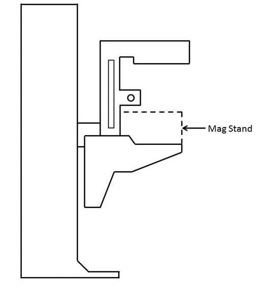
Figure 3. Diagram of a Mag Stand positioning on the breast platform.
Knee & Toe Space [M303.2.4]
Recommendation: The final subcommittee’s recommendations increased the overall knee and toe space to a minimum of 28 inches, from the initially proposed 25-inch absolute dimension. The final recommendation for knee clearance directly underneath the breast platform is a minimum of 18 inches and the final recommendation for the unobstructed floor space in front of the base support is a minimum of 17 inches. Each of these measurements creates a more accessible piece of imaging equipment balanced with the physical attributes and operation of the equipment.
Rationale
The issue of Clearance and Unobstructed Floor Space
The knee and toe clearance dimensions, as well as the unobstructed floor space dimensions, dictate how close a patient in a wheelchair can get to the mammography equipment. The initial NPRM dimensions used information for the clear space under a desk or table as the basis for the proposed regulation. Industry suggested the dimension might be different because mammography procedures require a person’s chest to be flush with the front of the breast platform. The subcommittee reviewed the existing data of wheelchair users1 and industry input on how these elements technically affect one another. Below is an overview of the rationale for each of the final recommended dimensions affecting clearances in front of the gantry. (Table 1)
Table 1. Critical Equipment Dimensions with the relevant Anthropomorphic Data
| Critical Dimension | Anthropomorphic Data /Rationale | Final Decision |
| Height of Breast Platform At Time of Measurement | Set point for assuring knee clearance at 27” above the ground Assures proportionality of each element to each other |
34" |
| Knee Clearance Depth at 27” above the ground | 95th percentile knee clearance measured from abdomen to front of person’s knees, female-only data | 18" minimum |
| Clearance Depth at Toe Height above the ground | 95th percentile knee clearance measured from abdomen to front of person’s legs at toe height above the ground, combined male and female data due to availability | 22" minimum |
| Toe Height | 95th percentile toe height, female-only data; consideration of breast platform moving to lower heights | 16" minimum |
| Overall Knee and Toe Clearance | Abdomen-to-toe depth, female only data; technical information; consideration of positioning methods | 28" minimum |
| Unobstructed Floor Space | Abdomen-to-caster wheel depth, combined male and female; technical information; consideration of positioning methods | 17" minimum |
One issue affecting how close the patient can get to the mammography machine is the base support, an essential equipment element that intrudes into the floor space. As discussed below, the purpose of the base support is to eliminate any instability caused by the weight of the cantilevered c-arm. Moving the c-arm further away from the gantry would increase the overall knee and toe clearance, but would also require an increase in the size of the base support in order to stabilize the equipment. Since the base support obstructs the floor space, resulting gains from increasing the knee and toe clearance are minimized because of the simultaneous increase in the size of the base support. The subcommittee considered this balance when making final decisions about overall knee and toe space and unobstructed floor space.
While discussing these issues, the subcommittee also considered positioning methods for patients using wheelchairs. During a mammography procedure, the patient’s chest is flush with the front edge of the breast platform and the technician positions the patient’s breast on the breast platform. In order to image as much of the breast as possible, patients cannot be seated in the “natural” sitting position. They will need to sit up straight in order to situate as much breast tissue as possible on the breast platform. For patients seated in a wheelchair, a common positioning technique is to place towels, pillows, or other positioning aids behind the patient’s back in order to sustain an upright pose during imaging. This upright pose is necessary regardless of how close the patient can naturally get to the breast platform. The pose reduces the abdomen-to-toe and abdomen-to-caster edge dimensions by a couple inches. The anthropomorphic data shows that 30.5 inches and 19.5 inches are the needed overall knee and toe clearance and unobstructed floor space dimensions, respectively. (Data shown below in Tables 2 and 3).
Table 2. Abdomen Depth Data to determine overall knee and toe clearance
| Percentile Value | |||||
| User Group | Median – 50th | 75th | 90th | 95th | Max |
| Female Manual Wheelchair Users (n=130) | 23.2 | 26.4 | 29.2 | 30.6 | 33.0 |
| Female Power Wheelchair Users (n=89) | 21.6 | 24.8 | 28.1 | 30.4 | 36.7 |
Table 3. Abdomen-Caster Edge Depth
| Percentile Value | |||||||
| User Group | Min | 5th | 10th | 50th | 90th | 95th | Max |
| Manual Wheelchair Users (n=101) | 2.0 | 5.6 | 6.8 | 11.4 | 17.1 | 18.5 | 20.3 |
| Power Wheelchair Users (n=67) | 4.1 | 6.0 | 7.8 | 10.9 | 17.6 | 19.3 | 21.9 |
In applying the various positioning considerations along with the data, measurements of 28 inches (full knee and toe clearance above the base support) and 17 inches (clearance underneath the breast platform) would capture nearly everyone. Looking purely at the anthropomorphic data above, these dimensions accommodate ~90% of the population. In adjusting for the needed upright pose, an adjustment of at least 2.5 inches is likely. If so, the equipment accommodates 95% of the population since the difference is ~2.5 inches less than the 95th percentile of the corresponding anthropomorphic dimensions. Members recognized that these dimensions are an optimal blend of accessibility and technical feasibility2 when balanced with the physical design and operation of the equipment,
Figure 4. Overview of the critical dimensions that define the knee and toe space underneath the breast platform.
Relationship of knee and toe space with breast platform
The shape of the breast platform affects the shape of the knee and toe space. Since the shape of the breast platform varies across different manufacturers and equipment, merely defining the knee clearance as the “knee clearance below the breast platform” would lose the interrelated aspect of these elements. This means a particular feature on the breast platform does not define the required location of the knee clearance. Instead, the knee space dimension is located with the platform at a specified height. By defining the height of the breast platform as the “set point” for the other dimensions, all clearances have a static measurement point that assures maximum clearances during operation of the equipment. Ultimately, the knee dimensions must be determined when the person’s breasts are on top of the breast platform and there must be sufficient clearance at the height of the person’s knees, as is shown in Figure 6 below. By using this approach, the subcommittee was able to maximize the clearances in relationship to the equipment operations.3
The NPRM proposed measuring the knee clearance under the breast platform at 27 inches above the ground. Industry used this dimension and determined the proportionate height of the breast platform at a height of 34 inches. The subcommittee agreed to this as a “set point” (Identified as “Breast Platform Height” in Figure 5 below). Thus, when the patient’s breast is on the breast platform, there must be sufficient knee clearance at 27 inches above the ground (“Knee Height” in Figure 5 below). These dimensions (27 and 34-inch heights) are the same as is defined by the current ADA/ABA accessibility standard to accommodate wheelchair users at desks. The dotted lines in Figure 6 below illustrates this dimension.
Figure 5. Using the height of the top of the breast platform as a set point for the knee and toe clearance measurements.
Figure 6. Illustration of current ADA/ABA standard to accommodate wheelchair users sitting at desks.
The two dimensions define the breast platform requirements for a person with the deep knees and a tall wheelchair. When the breast platform lowers to accommodate shorter patients in wheelchairs, there will be ample knee clearance for those patients. Conversely, as the breast platform moves up for patients who have longer torsos, the breast platform will just be moving away from their knees and legs, thus giving them ample space as well.
Toe Height
The NPRM defined the toe clearance at a height of 9 inches. However, as the breast platform moves up and down, it may intrude on the toe space. The subcommittee recommended that the toe height be set to 16 inches. Looking further at female-specific toe height data, the 95th percentile toe height was 13 inches for manual wheelchair users and 16.1 inches for power wheelchair users. As such, the subcommittee recommended that the toe height be set to 16 inches (when the breast platform is at the 34 inch height discussed above). This higher 16-inch measurement (compared to the originally proposed 9-inch toe height) would also minimize the chance of the breast platform hitting patients’ toes when the breast platform moves to some of its lower heights
Again, normally a toe space dimension defines a static unobstructed space. In this case, in order to get the maximum accessibility out of all the dimensions, the final recommendation requires the dimension of toe clearance is determined at the 34-inch breast platform height (see discussion above). This higher 16 inches measurement (compared to the originally proposed 9 inches toe height) would minimize the chance of the breast platform hitting patients’ toes when the breast platform moves to some of its lower heights. Providing this dimension helps define the outer limits of the breast platform configuration in a way that maximizes the dimensions for accessibility.
When considering toe height, it is more convenient to use the anthropomorphic model that defines toe height specifically, shown below in Figure 7 for manual chairs.
Figure 7. Anthropomorphic model used to analyze toe height.
If the toe height is at 16 inches above the ground when the breast platform is at 34 inches above the ground, we are accommodating the 90-95th percentile person. The toe height is more than enough to accommodate wheelchair users since the 95th percentile toe height is 13 inches. When the breast platform lowers to a 26-inch height, then the toe clearance height would be 8 inches. This maintains proportions likely to accommodate persons needing the breast platform at the lowest height since knee height is also less.
As discussed above, the minimum range of travel for the breast platform is 26 inches to 42 inches. When the top of the breast platform is at its lowest position of 26 inches, there is no need for knee clearance at 27 inches above the ground (knees will be lower than breast height). Defining knee and toe clearances based the lowest height breast platform at 26 inches may compromise taller patients in higher wheelchairs. As such, it is more appropriate to measure the dimensions of the knee and toe space set the breast platform to a higher height to ensure that the greatest required knee and toe clearances. Then, when the breast platform lowers to accommodate smaller patients, there will be more than enough clearance available.
The diagram below illustrates the final knee and toe clearance recommendations (Figure 8).
Figure 8. Summary of knee and toe clearance recommendations.
Notes:
1. Where possible, the subcommittee focused only on the anthropomorphic data of women, the primary group needing mammography.
2. The concept of technical feasibility is one found in other areas of access. It recognizes that there may be physical factors that make create limits to what functions can be achieved even with redesign. In mammography, the physical stability and operation of the equipment fall into this category. The committee recognizes that future visionaries may be able to “re-vision” new devices.
3. Given the differing shapes of mammography devices, defining the dimensions in relationship to each other with a static measurement point for the breast platform assures accessibility despite the varied shapes and dimensions of the breast platform. Otherwise,, it is quite possible to configure a piece of equipment that meets all the clearances yet does not provide accessibility if there is not a defined method of measuring the clearances in relationship to the breast platform.
4. Measured from the point on the floor where a perpendicular line intersects the front edge of breast platform shown in Figure 10.
Base Support [No specific provision—affects M303.2.4]
Recommendation: The final proposal on the base support is for 1½ inch high maximum base support with additional sloping permitted at 25 inches or beyond4 to the gantry if needed for additional structural support.
Rationale
The base support is of fundamental importance to mammography equipment and provides structural support, seismic stability, and installation safety. It does obstruct the floor space in front of the gantry and, thus, may limit how close a wheelchair can get to the equipment. To respond to this issue, industry proposed a configuration that would allow wheelchair footrests to ride over it so it causes minimal obstruction to the floor space in front of the gantry. To discuss the maximum base support height, the sub-committee looked at anthropomorphic data regarding footrest heights. The footrest height data measures the height from the floor to the top surface of the footrest at its proximal outside corner. To determine the necessary clearance for the footrests, the subcommittee used the calculated thickness of the footrests (~0.5 inch) minus the footrest height measurement. The ~0.5” thickness is the recommendation from the data supplied by Steinfeld and D’Souza. The anthropomorphic data, as well as the calculated footrest clearances, are below in Tables 4 and 5.
Table 4. Anthropomorphic data on measured footrest heights
| Device Type | Min | 5% | 10% | 50% | 90% | 95% | Max |
| Manual (n=101) | 1.2 | 1.7 | 2.2 | 4.1 | 7.2 | 10.0 | 36.2 |
| Power (n=67) | 1.8 | 2.7 | 3.1 | 4.8 | 8.8 | 10.5 | 16.9 |
Table 5. Actual footrest height clearances
| Device Type | Min | 5% | 10% | 50% | 90% | 95% | Max |
| Manual (n=101) | 0.7 | 1.2 | 1.7 | 3.6 | 6.7 | 9.5 | 35.7 |
| Power (n=67) | 1.3 | 2.2 | 2.6 | 4.3 | 8.3 | 10 | 16.4 |
A maximum base support height of 1.5 inches will provide room for the structural components necessary for an effective base support design and will also be accessible by ~92% of manual chair users and over 95% of power chair users.
The subcommittee also discussed adding an allowance for a sloped region at the base of the gantry. Many of the mammography machines today also have important informational displays at the base of the gantry, on top of the base support (shown as the checkered region in Figure 9 below) that display information such as compression force and compression thickness.
Industry input on these displays cited customer feedback. The technologists felt that while positioning the patient’s breast, they were naturally looking downward, and by having the display at the base of the gantry, they could watch the compression force and breast thickness readout while positioning the patient. They suggested this location for the display as a method for improving workflow. On other machines, this region has other mechanical and electrical components that are important to the function of the equipment.
At the full committee meeting, there was extensive discussion regarding the additional sloped region. Several members felt strongly that the additional sloped region must be justified by structural stability since displays could be located elsewhere. Members commented that not all equipment has displays in this region, so it seemed possible for industry to redesign the displays to create less interference.
The subcommittee agreed on adding an allowance for a sloped region as defined by Figure 10 below. Figure 11 below illustrates this region overlaid with the anthropomorphic data.
Figure 9. Location of the display area at the base of many mammography machines.
Figure 10. Summary of base support recommendations.
Figure 11. Base support configuration in red shown over the anthropomorphic data.
Steinfeld and D’Souza supplied this chart plotting their study’s findings on the depth of participant’s footrests. The black lines show the areas with no interference between the footrests and base support interface. The black lines illustrate areas where no footrests would intrude. However, based on the technical feasibility and clinical use considerations discussed in the above sections, industry provided the overlay configuration in red. The base support configuration illustrated above is the final recommendation.
The green dots in the above scatter plot illustration represent observed values for footrest height, (on the vertical axis) and footrest depth (on the horizontal axis) measured for manual wheelchair users to the abdomen point. The footrest clearances (calculated in Table 5 above) are ~0.5” lower than the footrest heights defined here. The footrest depth is the horizontal distance from the abdomen to the distal (forward-most) edge of the footrest. The subcommittee used the data for manual chairs because manual chairs are lower than the power chairs.
Summary Figure: Figure 12 shows the final recommended component dimensions in one diagram.
Figure 12. Summary of final clearance recommendations, to be measured when the top of the breast platform is at 34”.
Notes:
4. Measured from the point on the floor where a perpendicular line intersects the front edge of breast platform shown in Figure 10.
Standing Supports [M305.2]
Recommendation: The final recommendation of the subcommittee is to remove the requirement for standing supports in reference to mammography equipment. Instead, positioning supports should be required. To be useful, positioning supports must shaped for grasping, positioned within the reach range of all users, and be 12 inches long minimum when located on the moving c-arm or 18 inches long minimum when in a fixed location.
Rationale
The original criteria proposed in the NPRM included vertical standing supports on both sides of the equipment that were 18 inches in length. During discussion, there was general agreement that the real use of these supports is for positioning, and thus, not meant to support the full weight of the patient or to keep a patient in a standing position during the exam. Industry representatives posited that if a patient has limitations or balance issues severe enough to need standing assistance, then the healthcare provider should position her in a seated position for safe imaging. The primary use of these supports is for positioning of the arms during the imaging process to keep them out of the field of view of the image. For these purposes, the equipment criteria should designate these supports as positioning supports and be designed with the structural strength required for positioning activities.
Furthermore, since many types of mammography equipment mount the supports on the c-arm, they will move up and down with the breast platform. In these cases, they do not need to be as long as 18 inches to provide sufficient flexibility for patients to reach them. Industry representatives also indicated that there are controls in the area where these positioning supports are located. It is important that the patients’ hands do not accidentally hit these controls when they are holding the positioning supports. For this reason, industry will sometimes intentionally shorten the length of these handholds to less than the 18-inch proposal. Considering these factors, the full committee agreed that a 12-inch long positioning support would be sufficient if it moved with the movable breast platform.
Mammography Chair [M302]
Recommendation: The mammography chair is an essential piece of equipment allowing persons who are unable to stand or balance to sit for the diagnostic procedure. The chair must meet the elements of M302 with the additional requirement that any footrests must accommodate and ride over the base support.
References:
The following sources were referenced for the anthropomorphic data presented here. Specific citations are made in the full committee report.
IDeA Center Study at the University of Buffalo, New York: Summary analysis of wheelbase measurements on wheeled mobility devices.
IDeA Center at the University of Buffalo, New York: The Wheeled Mobility Anthropometry Project, Final Report, pages 89-92.
D’Souza, et al. “Clearance Space Envelopes of Wheeled Mobility Device Users for Computer Workstations”. Proceedings of the Human Factors and Ergonomics Society Annual Meeting 2012.
D’Souza, Steinfeld. “Revised Knee Clearance Depth and Footrest Clearance dimensions for sizing of mammography equipment.” Memorandum. April 23, 2013.
Notes:
1. Where possible, the subcommittee focused only on the anthropomorphic data of women, the primary group needing mammography.
2. The concept of technical feasibility is one found in other areas of access. It recognizes that there may be physical factors that make create limits to what functions can be achieved even with redesign. In mammography, the physical stability and operation of the equipment fall into this category. The committee recognizes that future visionaries may be able to “re-vision” new devices.
3. Given the differing shapes of mammography devices, defining the dimensions in relationship to each other with a static measurement point for the breast platform assures accessibility despite the varied shapes and dimensions of the breast platform. Otherwise,, it is quite possible to configure a piece of equipment that meets all the clearances yet does not provide accessibility if there is not a defined method of measuring the clearances in relationship to the breast platform.
4. Measured from the point on the floor where a perpendicular line intersects the front edge of breast platform shown in Figure 10.
User Comments/Questions
Add Comment/Question