Recommendations on Standards for the Design of Medical Diagnostic Equipment for Adults with Disabilities, Advisory Committee Final Report
Accessibility Standards for Medical Diagnostic Equipment
Medical Diagnostic Equipment Accessibility Standards
Sub-Committee Recommendations - Imaging Equipment
Final Report
June 2, 2013
The Subcommittee’s technical recommendations for imaging equipment (except Mammographic equipment) have taken into consideration the following technical criteria proposed in Chapter 3, part 1195 to Title 36 of the Code of Federal Regulations. Especially, Section M301, Diagnostic Equipment Used by Patients in Supine, Prone, or Side-Lying Position. However, given the enormous diversity of imaging equipment needed to achieve the broad range of diagnostic objectives Sections M302, Diagnostic Equipment used by Patients in Seated Position; M303, Diagnostic Equipment used by Patients Seated in a Wheelchair; and M304, Diagnostic Equipment used by Patients in Standing Position were considered and are noted in this report.
4. Perspectives of Equipment Types
4.3 Diagnostic Imaging Equipment
The diagnostic imaging equipment covered by this subcommittee had an extraordinary breadth and depth of its diversity of design, configurations, and principles of operation. This is the direct result of enormous variety of diagnostic tasks, clinical indications, and patient populations this equipment has been designed to serve both in a general manner as well as configurations that are highly optimized to provide optimized results for a particular clinical need.
The types of equipment covered and evaluated by the imaging subcommittee include:
-
Computed Tomography (CT)
-
Magnetic Resonance (MR)
-
Nuclear Medicine (Scintigraphy & Single Photon Emission Computed Tomography) (NM)
-
Positron Emission Tomography (PET)
-
X-Ray Fluoroscopy
-
X-Ray Radiography
-
X-Ray Interventional
-
X-Ray Mobiles
-
X-Ray C-arms
-
Dual-energy X-ray Absorptiometry (DXA)
-
X-Ray Mammography Biopsy Tables
-
PET/CT Combined Systems
-
NM/CT Combined Systems
-
PET/MR Combined System
These represent all virtually all diagnostic imaging systems except conventional Mammographic systems which were addressed by their own subcommittee and Ultrasound systems that due to their portability do not fall under the scope of these proposed standards.
This equipment consist mostly of large capital equipment, uses ionizing radiation (or a very strong magnetic field) to produce the images, has many years of service life, and represents significant investment to the facility. This equipment is also primarily permanently mounted in a fixed installation that special room siting design needs to be performed for. This special siting is the result of a variety of factors that include shielding of ionizing radiation or magnetic fields and specialized high power capacity electrical service. These systems do not have patient “operable parts” (i.e. the patient does not activate, deactivate, or adjust the equipment).
This equipment are all prescription use only devices, meaning that one must have a physician’s order before a person may receive an exam. The devices all must be operated by a trained and qualified technologist, who must be present during the exam to aid all patients onto the table, explain the exam process, and aid in properly positioning the patient.
This equipment represents US Food and Drug Administration (FDA) Class II medical devices that need pre-market notification to FDA (510(k) clearance) prior to being placed on the market. They must be design and manufactured under the Quality System Regulations for medical devices, 21CFR820, that includes design controls and good manufacturing practices. They must be tested and certified by an OSHA credentialed Nationally Recognized Testing Laboratory to demonstrate that they meet the basic safety and essential performance required by IEC60601-1 as well as the applicable IEC 60601-1 series of collateral and particular standards. The devices that produce X-rays must also be certified to FDA to meet the applicable performance standards for radiation safety found in 21CFRSubchapter J. The design process must conform include risk-management in accordance with ISO 14971. Radioactive Sources and Radiopharmaceuticals used for PET and NM are also regulated by the Nuclear Regulatory Commission.
A diagnostic imaging device’s the transfer surface (table) is both imaged through and also positions the patient during the imaging process, hence it plays in integral role in the diagnostic exam and is critical to achieving accurate diagnostic results and controlling radiation exposure to the patient. This, along with the mechanical, electrical, and physics aspects and needs of diagnostic imaging equipment create for a wide variety of designs and some inherent limitations to table (transfer surface) design possibilities.
The following is a rough grouping of diagnostic imaging devices that was used to help evaluate the criteria:
Equipment with bores: CT, PET, PET/CT, NM, NM/CT - Here the table plays an integral part in achieving the sub-mm dynamic positioning accuracy needed during the scan.
MR - This shares same aspects as equipment with bores, but has special considerations due to the very strong magnetic field.
DXA - This equipment necessitates positioning the x-ray source under the patient in a fixed, known geometry for diagnostic effectiveness and radiation dose concerns.
Conventional XR and Fluoroscopy - This equipment has rectangular, radio-translucent tables that may translate in both directions in the horizontal plane.
Mobile XR - These systems can be moved to the patient and can utilize detachable detectors that often can be placed behind the patient anatomy to be imaged without significant patient movement.
Interventional XR - This type of equipment, such as that used in cath labs and C-arms, has virtually all patients under some form of sedation prior to transfer, and is used in an invasive “interventional-like” procedure after initial diagnostic findings.
Prone breast biopsy tables - This unique design needs to accommodate room for the physician underneath the patient, patients may have some form of sedation, and is used in an invasive “interventional-like” procedure after initial diagnostic findings.
Diagnostic imaging tables mostly fall into two main groupings. One group is those tables used with “equipment with bores”, such as CT, MR, and NM systems. These tables tend to be long and relatively narrow in order to move the patient into and fit through the bore. They are typically rated for patients in excess of 400 lbs. They are capable of adjusting with the high precision (sub millimeter) accuracy needed for accurate diagnostic information both vertically for both patient loading and unloading procedures, and horizontally in one direction (into the bore).
The other group is those tables used on X-Ray system. These too are typically rated for patients in excess of 400 lbs, but are wider than those used with equipment with bores and in many cases are able to move horizontally in two directions. The may not be designed to adjust vertically, but some are designed to rotate to place the patient in a more vertical position needed for specific diagnostic exam needs. Tables for DXA equipment present a noteworthy uniqueness because for both diagnostic and mechanical reasons, they are fixed and do not adjust in any direction.
It must be noted that for patient support devices must meet applicable safety factors as delineated in IEC 60601-1. These factors typically range from 4x to 8x. This means a patient table labeled to support a 500 lb patient must actually be designed and tested at up to 4000 lbs. This has significant implications for adjustable height table design as many design loose mechanical advantage as they go lower.
Many X-Ray systems have imaging components such as X-Ray tubes, high voltage generators, and/or detectors located under the table (transfer surface). The fact that the tables used for diagnostic imaging equipment must not only support large weights, precisely position and image, and potentially accommodate imaging components make redesign of imaging tables challenging at best, but perhaps in some cases infeasible. In all cases, due to the complexity of the equipment and the regulatory requirements, a redesign of an imaging system or its table would require a multi-year process.
One type of equipment stood out as unique are systems used for interventional and biopsy procedures. Both interventional procedures and biopsies are technically considered “diagnostic” because they can provide diagnostic information. These systems however, frequently require all patients to under some form of sedation prior to transfer. Because of the use of sedation, their invasiveness, and that these exams are a secondary follow-up to a primary diagnostic finding, they seem more related treatment and hence the subcommittee and the full advisory committee believes they should be considered out of scope for these standards and hence exempted.
For those systems that will be subject to the new standards, there are certain constraints and performance considerations:
-
Must maintain same degree of diagnostic performance for all patients.
-
Huge variation of clinical applications and patient needs.
-
Technical and diagnostic constraints.
-
Must maintain accessibility for all patients and patient conditions.
-
Must maintain health care professional access to patient and patient support equipment.
-
Must maintain infection control constraints.
-
Must continue to adhere to FDA and international standards.
-
There is not a one-size-fits-all solution.
All current diagnostic imaging equipment does not meet a minimum transfer height of 17 inches, however some equipment with bore tables do currently meet 19 inches. However, with equipment redesign there are some that may (e.g. CT), but most will encounter a significant technical or diagnostic barrier if the actual transfer surface (table) must be altered. Creative and alternative solutions are needed to increase independent transfer for maximum adoption by facilities (e.g. “accessibility packages”).
The subcommittee believes alternate criteria or “accessibility packages”, to strive for equivalent facilitation, will be needed to best improve independent access in the most meaningful way while adhering to the above constraints and considerations. Accessibility Packages would include accessory components, ancillary equipment, and/or siting design requirements. Accessibility packages may be able a timely, cost effective solution that may also be able to be applied to existing equipment to increase accessibility.
Section 201(h) of the Federal Food Drug & Cosmetic Act includes accessories with the definition of a medical device, and the IEC 60601-1 international standard for medical electrical equipment also identifies that medical electrical equipment includes those accessories that are necessary to enable the normal use of the equipment which includes facilitation of its use.
Section 5 of this report contains some figures of conceptual ideas for accessibility accessories.
Patient Positions during Diagnostic Imaging
The vast majority of diagnostic imaging exams are conducted while the patient is lying on the table; hence the focus of the subcommittee was for the proposed standards in Section M301. However, given the enormous diversity of imaging equipment needed to achieve the broad range of diagnostic objectives Sections M302, Diagnostic Equipment used by Patients in Seated Position; M303, Diagnostic Equipment used by Patients Seated in a Wheelchair; and M304, Diagnostic Equipment used by Patients in Standing Position were considered and are noted in this report.
There are some Nuclear Medicine systems that have a unique design for convenience where the system’s table can pivot out of the way to allow a scan while a patient seated (in a chair or wheelchair). However, given the clinical input from the radiologist that presented to the advisory committee, an equivalent diagnostic exam, in all cases may be obtained while a patient is on the table. As such both the subcommittee and the full advisory committee agreed that for these types of Nuclear Medicine systems, only the M301 criteria should be applied.
Some specialized MR and possibly other modality devices designed and used for extremity scans may not be provided with a table. In such cases the patient chair should comply with the conclusions of the tables and chairs subcommittee to the extent practical while still meeting the diagnostic needs.
Some X-Rays exams are performed with a wall stand in use where the patient is asked to stand. In these situations M304 would apply. However it is likely that the standing supports may need to be an accessory or a mounting in the room. Additionally, given that these supports may also need to serve the diagnostic purpose of a positioning aid some of the dimensions proposed in M305.3 may need to be adjusted in order to maintain diagnostic efficacy.
5. Recommendations
5.3 Diagnostic Imaging Equipment
One type of equipment stood out as unique are systems used for interventional X-Ray and breast prone biopsy procedures. Both interventional procedures and biopsies are technically considered “diagnostic” because they can provide diagnostic information. These systems however, frequently require all patients to under some form of sedation prior to transfer. Because of the use of sedation, their invasiveness, and that these exams are a secondary follow-up to a primary diagnostic finding, they seem more related treatment and hence the subcommittee and the full advisory committee believes they should be considered out of scope for these standards and hence exempted.
As discussed in Section 4.3, the requirements for diagnostic imaging equipment do not apply to patients in a seated (chair or wheelchair) when the imaging system is provided with and/or intended to be used for patients in prone, supine, or Side-Lying Position. Some X-Rays exams are performed with a wall stand in use where the patient is asked to stand. In these situations M304 would apply. However it is likely that the standing supports may need to be an accessory or a mounting in the room. Additionally, given that these supports may also need to serve the diagnostic purpose of a positioning aid some of the dimensions proposed in M305.3 may need to be adjusted in order to maintain diagnostic efficacy.
M301.2.1 Transfer Surface Height
Subcommittee Recommendation:
The imaging subcommittee decided to not specifically come up with a recommendation for transfer height, rather leaving that to the full committee’s determination and then have it applied to diagnostic imaging equipment.
Rationale: For many types of imaging equipment it will not be feasible to provide a transfer surface meeting the considered minimum height whether it is 17, 18, or 19 inches. The same is true for height adjustability for DXA and some X-Ray systems. In those instances an alternate means of access will need to be provided such as the use of auxiliary/ancillary equipment and accessories (“Accessibility Package”).
Some CT tables can currently meet an 18 or 19 inch height and with redesign, more tables for use with equipment with bores would be able to. Most tables for use with equipment for bores are height adjustable. The limitations with these types of tables are that they are typically designed to accommodate >400 lb patients while performing sub-millimeter diagnostic positioning. These tables need to typically be designed with an 8x safety factor and hence have sizable support mechanisms, some of which are designed such that as the table is lowered, mechanical advantage is lost. Every inch is significant from a design perspective.
Tables used for MR imaging must also meet the requirements of being in very strong magnetic fields. Additionally these magnetic fields also preclude use of a patient’s mobility device in the exam room. However, currently there are MR table designs that are detachable and can be moved outside of the MR room where the patient can transfer. In such cases these tables become very similar to CT tables for accessibility considerations.
Many X-Ray systems have imaging components such as X-Ray tubes, high voltage generators, and/or detectors located under the table (transfer surface). X-Ray tables are also typically rated for patients in excess of 400 lbs, but are wider than those used with equipment with bores and in many cases are able to move horizontally in two directions. The may not be designed to adjust vertically, but some are designed to rotate to place the patient in a more vertical position needed for specific diagnostic exam needs. Tables for DXA equipment present a noteworthy uniqueness because for both diagnostic and mechanical reasons, they are fixed and do not adjust in any direction.
Section 4.3 of this report contains additional considerations from the imaging subcommittee.
Figure 5.3-1: This is picture of a CT system (this one has decals on it for use in a children’s hospital). It is also representative of a MR table. The table on this particular model is 7+ ft long, about 24 inches wide, and has a minimum height of about 18 inches. Note the emergency extraction handle at the foot end of the table. Also note that there is not structural material under the table side covers where transfer supports could sufficiently be anchored.
Figure 5.3-2: This is a picture of a PET/CT system. The PET gantry is located behind the CT gantry, under a single cover. The patient table is virtually identical to the CT table in Figure 5.3-1, however it must be mounted on a transporter (adding 4-5 inches it the minimum height) in order to move it closer to the gantry for the PET scan. Simply having a longer cradle is not done because the cradle must be of material that is virtually transparent to X-rays, and this requirement results in there being some table “sag” when it is extended with a patient on it. A longer cradle will have more sag to the point of not being diagnostically acceptable…hence the transporter.
Figure 5.3-3: This is a picture of a NM/CT system. The NM detector heads are located in front of the CT scanner. These heads are able to rotate 360 degrees. The patient table top design is similar to that of a CT system; it is about 24 inches wide in total. On this model the minimum height is 23.2 inches. This is due to the different type of lifting mechanism employed because the table base just needs to move straight up and down. This type of design is also found on other manufactures’ CT and MR tables. The table side covers have the same issues discussed for the CT table in Figure 5.3-1.
Figure 5.3-4a
Figure 5.3-4c
Figure 5.3-4c
Figure 5.3-4: These pictures show an Angulating Radiographic and Fluoroscopic Exam Table whose fixed height is approximately 34.5 inches. The height is the result of the design being able to angulate to perform certain types of diagnostic exams and also to accommodate imaging components under the table such as X-Ray tubes, high voltage generators, and detectors. The table surface is also able to move in two directions horizontally. Also note the equipment imaging components on the opposite side of where the patient transfers.
Figure 5.3-5a
Figure 5.3-5b
Figure 5.3-5: These pictures show a Dual Energy X-ray Absorptiometry (DXA) system for Osteoporosis assessment. The table heights are fixed due to the diagnostic need for a fixed geometry. The table heights are typically 25 - 28 inches and are dictated by the needing the X-Ray source below the table for diagnostic and radiation dose considerations. Also note the equipment imaging components on the opposite side of where the patient transfers.
The subcommittee and full committee believes alternate criteria or “accessibility packages”, to strive for equivalent facilitation, will be needed to best improve independent access in the most meaningful way while adhering to the above constraints and considerations. Accessibility Packages would include accessory components, ancillary equipment, and/or siting design requirements. Accessibility packages may be able a timely, cost effective solution that may also be able to be applied to existing equipment to increase accessibility.
The following figures show some concepts of accessories to address table height that could be included an accessibility package. The accessory or installation would result in decreasing the distance between the transfer surface and the surface where the mobility device is located.
Figure 5.3-6: Flush mounted scissors lift concept (not to scale). The left side shows a flush mounted lift as in the down position while the right side shows it in its elevated position. The lift would need to appropriately sized and ramped and include edge protection.
Figure 5.3-7: Elevated platform or possibly “full” floor concept (not to scale). This drawing illustrates the idea of raising the floor instead of lowering the table. This could possibly be accomplished either by a raised platform on the transfer side as shown in the drawing or by building up the floor in the entire room. If an installation is new, it may also be possible to lower the mounting surface of the equipment. An elevated platform would need to appropriately sized and ramped and include edge protection.
M301.2.2 Transfer Surface Size
Subcommittee Recommendation: (Also agreed to by the full committee).
A. The minimum size of the transfer surface is 28 inches wide minimum and 21 inches deep minimum and is located such that the long dimension of 28 inches is be located parallel to the patient scanning/imaging table side at a location designated by the equipment manufacturer.
B. When the transfer surface is located as described above in “A”, the width of the patient scanning/imaging table (side to side) at the designated transfer location should be 28 inches minimum or the maximum possible/practicable, but in all cases a minimum of 21 inches. Note: Alternate means of temporarily widening the table at the designated transfer location during transfer may be feasible.
Rationale: Diagnostic imaging equipment is accessed by all individuals from one of the long sides of the table. Dependent on room layout and other ancillary equipment, both long sides of equipment with a bore tables may be available for transfer. However, many X-Ray system tables and all DXA tables will have part of the imaging equipment support located on one of the long sides and only all transfers are made from the other.
Because diagnostic imaging equipment uses tables for imaging and the tables are always accessed from their long sides, all current equipment meets the 28 inch minimum width and also meets the 21 inch minimum depth for item “A”.
All X-Ray tables meet the 28 inch table width for item “B”. However, because of considerations such as bore size, not all tables used with equipment with bores meet the 28 inch width criteria from “B” (but they do all meet the 21 inch minimum).
The subcommittee created the additional 28 inch table width criteria in “B” because the transfer surface in diagnostic imaging equipment is different than that of exam tables or chairs. With an exam table or chair there is additional table or chair “beyond” the transfer depth. However, with some imaging equipment, due to the transfer from the long side of the table, there may not be any more table beyond the transfer depth.
The subcommittee understands the potential practical limitations that may be encountered on tables used with equipment with bores and therefore only had the 28 inch width criteria for “B” be located at the manufacture designated transfer location.
The possible narrowness of some diagnostic imaging tables was addressed by the subcommittee by their recommendations for M301.3 for transfer supports. The subcommittee sees their recommendations for M301.2.2 transfer surface size and M301.3 to work together to facilitate independent transfers.
Below is a schematic to help illustrate the proposed requirements.
Figure 5.3-8: Schematic of Transfer Surface Size for Diagnostic Imaging Equipment
M301.2.3 Transfer Surface Transfer Sides
Subcommittee Recommendation: (Also agreed to by the full committee.)
The option to transfer will be required only on one long side of the patient scanning/imaging table and not at the “foot” or “head” end of such surfaces.
Note: most installations can accommodate transfer from either long side for equipment with bores (siting and site dependent). However X-ray systems are likely to, and DXA systems will have equipment obstructions on one long side. Therefore, where feasible within the medical equipment design, the ability to have transfer access from two sides (either two long sides or a long and short side) is desired.
Rationale: Diagnostic imaging equipment is accessed by all individuals from one of the long sides of the table. Dependent on room layout and other ancillary equipment, both long sides of equipment with a bore tables may be available for transfer. However, many X-Ray system tables and all DXA tables will have part of the imaging equipment support located on one of the long sides and only all transfers are made from the other.
The head and foot ends of the table are likely to have obstructions such as extraction handles, the gantry, or patient positioning devices. Imaging tables are usually not intended to be access from the head or foot end because the patient would need to “scoot” a long distance to get into the proper position for their exam.
M301.3.1 Transfer Supports
Subcommittee Recommendation: (Also agreed to by the full committee.)
A) For transfer depths less than or equal to 24 inches a transfer support will be located opposite the transfer side.
Note: if transfer is possible from either of the long sides of the table, then a transfer support should be able to be located (or relocated) to the side opposite where the actual transfer is occurring.)
A.1) A transfer support will extend horizontally along the side of the patient scanning/imaging table at least the minimum width of the transfer surface, but in all cases a 28 inches minimum. It will be located at the designated transfer location.
Note: The transfer support will likely need to be separate from the patient imaging table and this is acceptable if such a support meets all relevant technical criteria and is designed to address entrapment hazards. Also note that some equipment has bi-directional table movement which may complicate or in some cases possibly prevent location of a support.
B) For transfer depths greater than 24 inches a positioning support will be located opposite the transfer side.
Note 1: As with other patient positioning aids, a positioning support’s load bearing design may be different than that of a transfer support. These requirements are already addressed by international standards that medical device manufacturers need to follow (e.g. risk management (ISO 14971); IEC60601-1; and use of IEC60601-2-52 as a possible reference.
Note 2: if transfer is possible from either of the long sides of the table, then a positioning support should be able to be located (or relocated) to the side opposite where the actual transfer is occurring.
B.1) A positioning support will extend horizontally along the side of the patient scanning/imaging bed/table and be 12 - 16 inches in length and 3 - 6 inches above the transfer surface. It will be located at a position designated by the manufacturer for optimal positioning assistance.
Note: The positioning support may need to be separate from the patient imaging table and this is acceptable if such a support meets all relevant technical criteria and is designed to address entrapment hazards. Also note that some equipment has bi-directional table movement which may complicate or in some cases possibly prevent location of a support.
C) The maximum distance from the transfer surface to either the transfer support or the positioning support is 1.5 inches. However, an exception of up to 3 inches is acceptable for foldable, collapsible, removable, and articulating supports.
Rationale: The subcommittee created this two part standard because the transfer surface in diagnostic imaging equipment is different than that of exam tables or chairs. With an exam table or chair there is additional table or chair “beyond” the transfer depth. However, with some imaging equipment, due to the transfer from the long side of the table, there may not be any more table beyond the transfer depth. Hence for the cases of narrow (≤ 24”) tables a larger and more substantial transfer support is called for. This transfer support is intended to be used to facilitate transfers and as a prevention for a patient from falling over the table’s opposite side. It there must be designed for this use case. 24 inches was chosen based on input of a person’s maximum reach.
For wider tables (>24”), a transfer support would not be usable because of its distance from the patient using a mobility device. However, the subcommittee saw the need to still have some form of support bar on the opposite side of the table to be used as a positioning aid once the transfer is completed. Because the patient would now be primarily supported by the table, this positioning aid would need to be designed for the loadings of positioning-only use case. The location of this positioning aid will be determined by the manufacture because they have the best knowledge of the particular equipment’s clinical use cases and positioning needs.
The subcommittee recognizes that diagnostic imaging tables either due to bi-directional horizontal movement such as for some X-Ray tables or a lack of sufficient structural integrity on the side of the table may either make it technically very challenging to provide a positioning or transfer support. One means to address this may be by not mounting the support to the table itself, rather the support could be an accessory as part of an accessibility package.
Another critical factor that must be considered is the ability of HCP’s to access the patient during an imaging exam for proper position, administration of imaging agents or other drugs, patient monitoring, etc. Additionally, because in most cases the tables on diagnostic imaging move during the exam and there may be both moveable and stationary parts of the table, design consideration must be given to avoid tubing and other such items that may be attached to the patient from getting caught in a tableside support and pulled out of a patient.
The allowed distance to the transfer or positioning support was chosen to consistent with that of developed by the stretchers subcommittee.
Below is a schematic to help illustrate the proposed requirements.

Figure 5.3-9: Schematic of Transfer Surface Size and Patient Support for Diagnostic Imaging Equipment
The following figures show some concepts of accessories to address transfer and positioning supports that could be included an accessibility package.
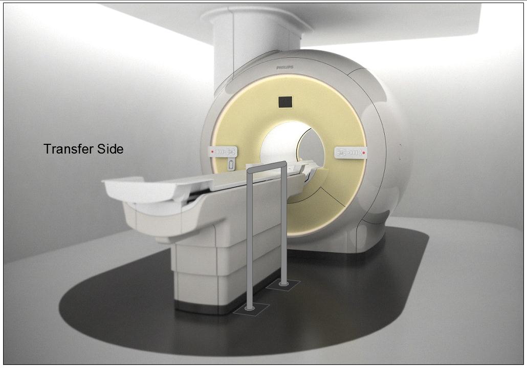
Figure 5.3-10: Illustration of a concept (not to scale) for a detachable floor mounted support. The support could be made to be both height adjustable and detachable at floor level.
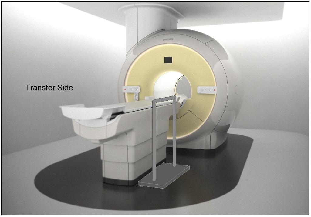
Figure 5.3-11: Illustration of a concept (not to scale) for a wheeled support (wheels would lock and base sufficiently robust and sized for appropriate loadings). The support could be made to be height adjustable.
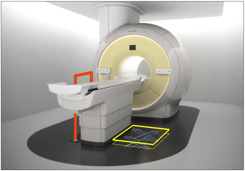
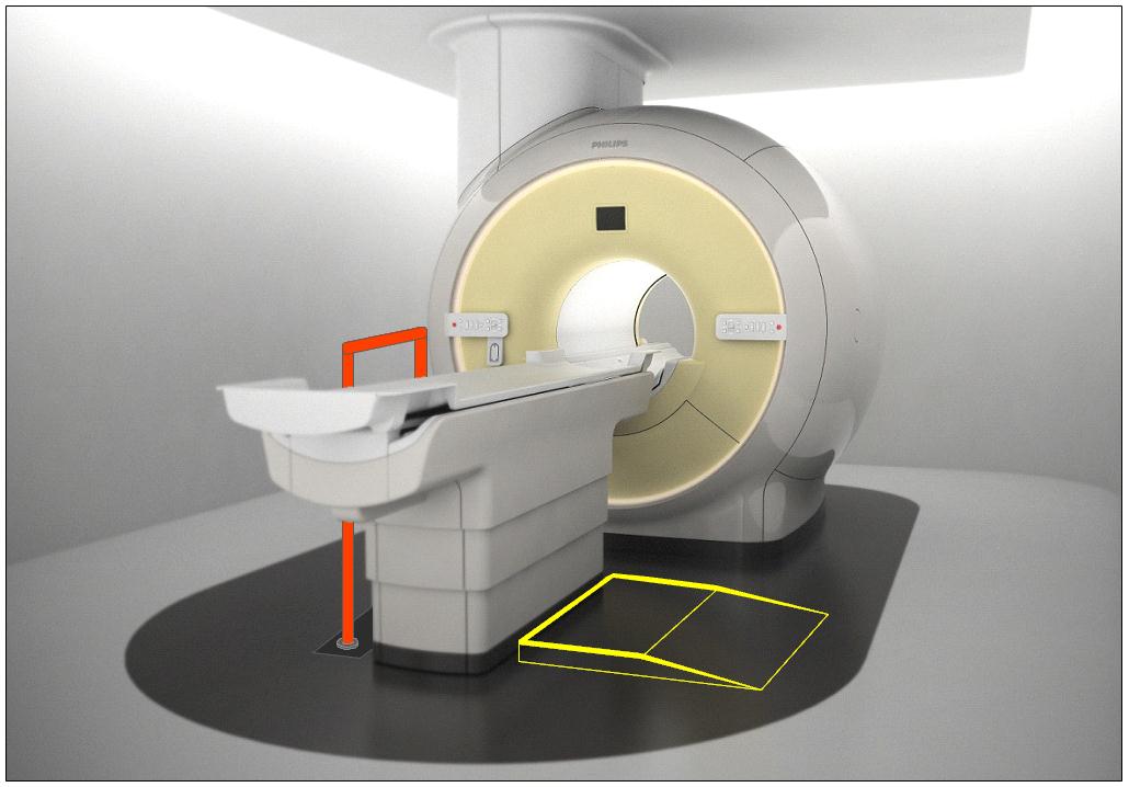
Figure 5.3-12: Illustration of the concept (not to scale) of accessories deployed as part of an accessibility package. The top illustration is shows a floor mounted support combined with scissor lift of Figure 5.3-6. The lower illustration shows the floor mounted support combined with the elevated platform of Figure 5.3-7.
M301.4 Lift Compatibility
Subcommittee Recommendation: (Also agreed to by the full committee.)
An overhead lift (and possibly a gurney-based transfer) may be used in lieu of the provisions for clearances in or around the base of equipment to accommodate the legs of portable floor lifts.
Note: in some circumstances such as in-room MR, the option for a room layout for gurney transfer would be appropriate.
Rationale: The subcommittee recommended the alternate means of using an overhead lift instead of providing clearances for portable lifts because: 1) a ceiling mounted lift can have advantages for better patient transfer and positioning over a portable lift because the portable lift would need to access the diagnostic imaging table from its side or its far foot-end; and 2) table structural design and/or room layout may be such that providing the clearances in and around the base per M301.4.1 and M301.4.2 may be either technically difficult or impractical. Overhead lifts are already currently installed as accessories for some imaging systems.
Overhead lifts are not possible to be used in the MR exam room due to the magnetic fields. Because of this, or for other cases where an overhead lift would be impossible, a gurney-based transfer was considered acceptable provided the gurney met the new standards, even though a double transfer is not ideal.
Below is a picture of an existing CT room with a ceiling mounted overhead lift. Note the degree of flexibility and advantages that this design provides over a portable lift scenario, such as: either side transfer, desired patient orientation prior to transfer, always being available to the patient, no need to manually move the patient by hand, and the ability to move the lift completely out of the way when not needed.
Figure 5.3-13: An existing CT room with a ceiling mounted overhead lift.
6. Transfer Surface Height
6.3 Diagnostic Imaging Equipment
Refer to the Rationale found in Section 5.3 for M301.2.1 and to Section 4.3.
For many types of imaging equipment it will not be feasible to provide a transfer surface meeting the considered minimum height whether it is17, 18, or 19 inches. The same is true for height adjustability for DXA and some X-Ray systems. In those instances an alternate means of access will need to be provided such as the use of auxiliary/ancillary equipment and accessories (“Accessibility Package”).
Given that diagnostic imaging tables are in integral part of the exam and required for accurate results, their design to support very heavy patients, and in some types the existence of imaging components under the table and specialized diagnostic abilities, modifications to the table to go lower and/or be adjustable will always present many design challenges. As such every inch is significant both for designing tables that can go low enough to meet the new standard and in design of accessories or room siting as alternate means to attempt to meet the new standards.
As noted in Section 5.3, the imaging subcommittee did not take a formal position on the transfer surface height. However, during the full committee meeting the manufacturers of diagnostic imaging equipment voted for the “compromise” height of 18 inches.
User Comments/Questions
Add Comment/Question