Recommendations on Standards for the Design of Medical Diagnostic Equipment for Adults with Disabilities, Advisory Committee Final Report
M301.3.1 Transfer Supports
Subcommittee Recommendation: (Also agreed to by the full committee.)
A) For transfer depths less than or equal to 24 inches a transfer support will be located opposite the transfer side.
Note: if transfer is possible from either of the long sides of the table, then a transfer support should be able to be located (or relocated) to the side opposite where the actual transfer is occurring.)
A.1) A transfer support will extend horizontally along the side of the patient scanning/imaging table at least the minimum width of the transfer surface, but in all cases a 28 inches minimum. It will be located at the designated transfer location.
Note: The transfer support will likely need to be separate from the patient imaging table and this is acceptable if such a support meets all relevant technical criteria and is designed to address entrapment hazards. Also note that some equipment has bi-directional table movement which may complicate or in some cases possibly prevent location of a support.
B) For transfer depths greater than 24 inches a positioning support will be located opposite the transfer side.
Note 1: As with other patient positioning aids, a positioning support’s load bearing design may be different than that of a transfer support. These requirements are already addressed by international standards that medical device manufacturers need to follow (e.g. risk management (ISO 14971); IEC60601-1; and use of IEC60601-2-52 as a possible reference.
Note 2: if transfer is possible from either of the long sides of the table, then a positioning support should be able to be located (or relocated) to the side opposite where the actual transfer is occurring.
B.1) A positioning support will extend horizontally along the side of the patient scanning/imaging bed/table and be 12 - 16 inches in length and 3 - 6 inches above the transfer surface. It will be located at a position designated by the manufacturer for optimal positioning assistance.
Note: The positioning support may need to be separate from the patient imaging table and this is acceptable if such a support meets all relevant technical criteria and is designed to address entrapment hazards. Also note that some equipment has bi-directional table movement which may complicate or in some cases possibly prevent location of a support.
C) The maximum distance from the transfer surface to either the transfer support or the positioning support is 1.5 inches. However, an exception of up to 3 inches is acceptable for foldable, collapsible, removable, and articulating supports.
Rationale: The subcommittee created this two part standard because the transfer surface in diagnostic imaging equipment is different than that of exam tables or chairs. With an exam table or chair there is additional table or chair “beyond” the transfer depth. However, with some imaging equipment, due to the transfer from the long side of the table, there may not be any more table beyond the transfer depth. Hence for the cases of narrow (≤ 24”) tables a larger and more substantial transfer support is called for. This transfer support is intended to be used to facilitate transfers and as a prevention for a patient from falling over the table’s opposite side. It there must be designed for this use case. 24 inches was chosen based on input of a person’s maximum reach.
For wider tables (>24”), a transfer support would not be usable because of its distance from the patient using a mobility device. However, the subcommittee saw the need to still have some form of support bar on the opposite side of the table to be used as a positioning aid once the transfer is completed. Because the patient would now be primarily supported by the table, this positioning aid would need to be designed for the loadings of positioning-only use case. The location of this positioning aid will be determined by the manufacture because they have the best knowledge of the particular equipment’s clinical use cases and positioning needs.
The subcommittee recognizes that diagnostic imaging tables either due to bi-directional horizontal movement such as for some X-Ray tables or a lack of sufficient structural integrity on the side of the table may either make it technically very challenging to provide a positioning or transfer support. One means to address this may be by not mounting the support to the table itself, rather the support could be an accessory as part of an accessibility package.
Another critical factor that must be considered is the ability of HCP’s to access the patient during an imaging exam for proper position, administration of imaging agents or other drugs, patient monitoring, etc. Additionally, because in most cases the tables on diagnostic imaging move during the exam and there may be both moveable and stationary parts of the table, design consideration must be given to avoid tubing and other such items that may be attached to the patient from getting caught in a tableside support and pulled out of a patient.
The allowed distance to the transfer or positioning support was chosen to consistent with that of developed by the stretchers subcommittee.
Below is a schematic to help illustrate the proposed requirements.
Figure 5.3-9: Schematic of Transfer Surface Size and Patient Support for Diagnostic Imaging Equipment
The following figures show some concepts of accessories to address transfer and positioning supports that could be included an accessibility package.
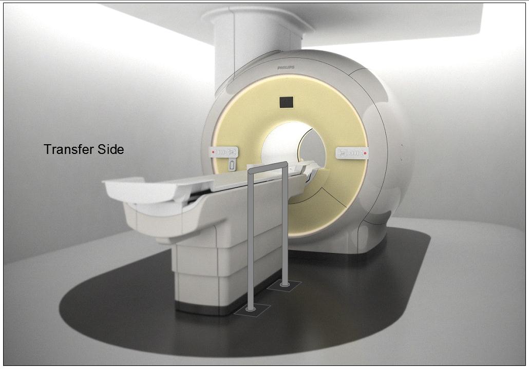
Figure 5.3-10: Illustration of a concept (not to scale) for a detachable floor mounted support. The support could be made to be both height adjustable and detachable at floor level.
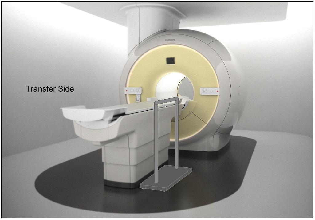
Figure 5.3-11: Illustration of a concept (not to scale) for a wheeled support (wheels would lock and base sufficiently robust and sized for appropriate loadings). The support could be made to be height adjustable.
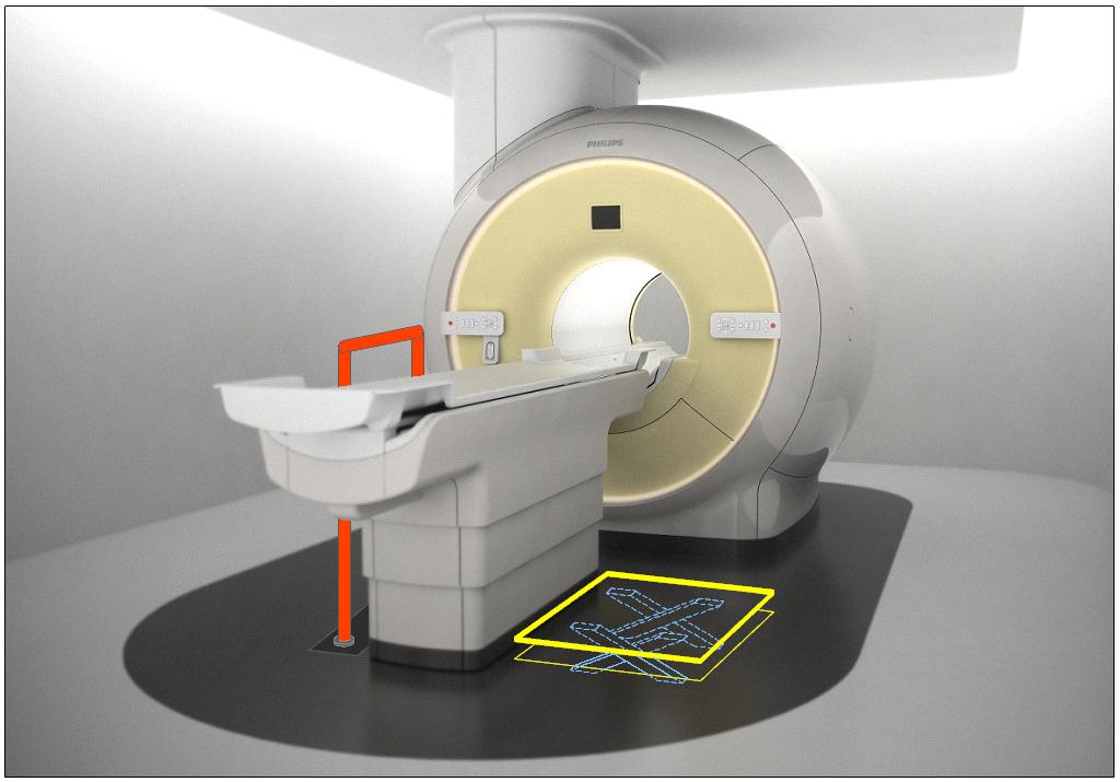
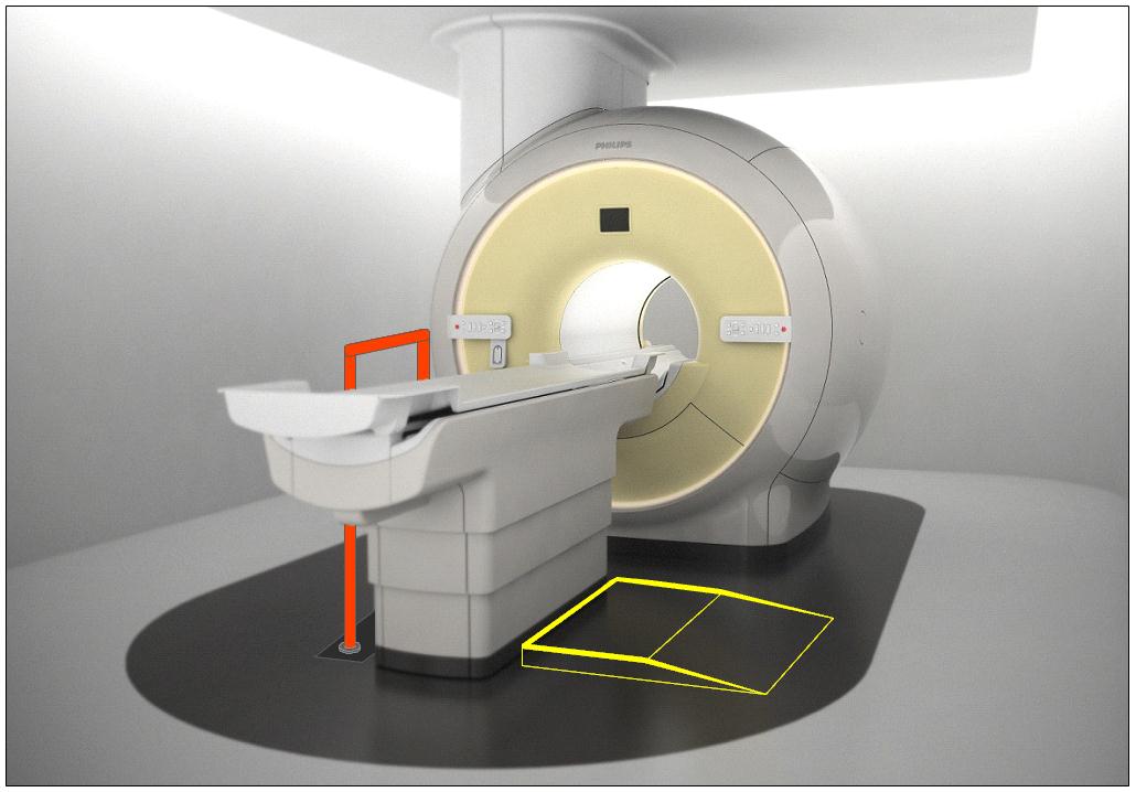
Figure 5.3-12: Illustration of the concept (not to scale) of accessories deployed as part of an accessibility package. The top illustration is shows a floor mounted support combined with scissor lift of Figure 5.3-6. The lower illustration shows the floor mounted support combined with the elevated platform of Figure 5.3-7.
User Comments/Questions
Add Comment/Question