Recommendations on Standards for the Design of Medical Diagnostic Equipment for Adults with Disabilities, Advisory Committee Final Report
M301.2.1 Transfer Surface Height
Subcommittee Recommendation:
The imaging subcommittee decided to not specifically come up with a recommendation for transfer height, rather leaving that to the full committee’s determination and then have it applied to diagnostic imaging equipment.
Rationale: For many types of imaging equipment it will not be feasible to provide a transfer surface meeting the considered minimum height whether it is 17, 18, or 19 inches. The same is true for height adjustability for DXA and some X-Ray systems. In those instances an alternate means of access will need to be provided such as the use of auxiliary/ancillary equipment and accessories (“Accessibility Package”).
Some CT tables can currently meet an 18 or 19 inch height and with redesign, more tables for use with equipment with bores would be able to. Most tables for use with equipment for bores are height adjustable. The limitations with these types of tables are that they are typically designed to accommodate >400 lb patients while performing sub-millimeter diagnostic positioning. These tables need to typically be designed with an 8x safety factor and hence have sizable support mechanisms, some of which are designed such that as the table is lowered, mechanical advantage is lost. Every inch is significant from a design perspective.
Tables used for MR imaging must also meet the requirements of being in very strong magnetic fields. Additionally these magnetic fields also preclude use of a patient’s mobility device in the exam room. However, currently there are MR table designs that are detachable and can be moved outside of the MR room where the patient can transfer. In such cases these tables become very similar to CT tables for accessibility considerations.
Many X-Ray systems have imaging components such as X-Ray tubes, high voltage generators, and/or detectors located under the table (transfer surface). X-Ray tables are also typically rated for patients in excess of 400 lbs, but are wider than those used with equipment with bores and in many cases are able to move horizontally in two directions. The may not be designed to adjust vertically, but some are designed to rotate to place the patient in a more vertical position needed for specific diagnostic exam needs. Tables for DXA equipment present a noteworthy uniqueness because for both diagnostic and mechanical reasons, they are fixed and do not adjust in any direction.
Section 4.3 of this report contains additional considerations from the imaging subcommittee.
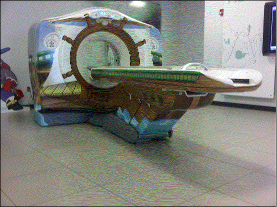
Figure 5.3-1: This is picture of a CT system (this one has decals on it for use in a children’s hospital). It is also representative of a MR table. The table on this particular model is 7+ ft long, about 24 inches wide, and has a minimum height of about 18 inches. Note the emergency extraction handle at the foot end of the table. Also note that there is not structural material under the table side covers where transfer supports could sufficiently be anchored.
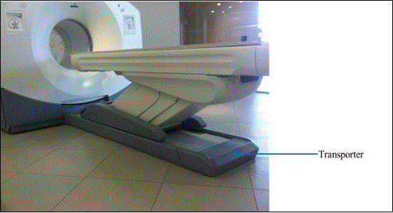
Figure 5.3-2: This is a picture of a PET/CT system. The PET gantry is located behind the CT gantry, under a single cover. The patient table is virtually identical to the CT table in Figure 5.3-1, however it must be mounted on a transporter (adding 4-5 inches it the minimum height) in order to move it closer to the gantry for the PET scan. Simply having a longer cradle is not done because the cradle must be of material that is virtually transparent to X-rays, and this requirement results in there being some table “sag” when it is extended with a patient on it. A longer cradle will have more sag to the point of not being diagnostically acceptable…hence the transporter.
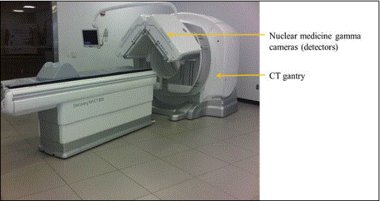
Figure 5.3-3: This is a picture of a NM/CT system. The NM detector heads are located in front of the CT scanner. These heads are able to rotate 360 degrees. The patient table top design is similar to that of a CT system; it is about 24 inches wide in total. On this model the minimum height is 23.2 inches. This is due to the different type of lifting mechanism employed because the table base just needs to move straight up and down. This type of design is also found on other manufactures’ CT and MR tables. The table side covers have the same issues discussed for the CT table in Figure 5.3-1.
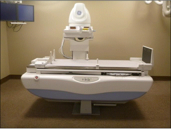
Figure 5.3-4a
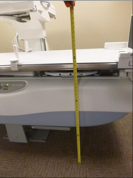
Figure 5.3-4c
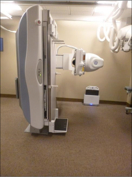
Figure 5.3-4c
Figure 5.3-4: These pictures show an Angulating Radiographic and Fluoroscopic Exam Table whose fixed height is approximately 34.5 inches. The height is the result of the design being able to angulate to perform certain types of diagnostic exams and also to accommodate imaging components under the table such as X-Ray tubes, high voltage generators, and detectors. The table surface is also able to move in two directions horizontally. Also note the equipment imaging components on the opposite side of where the patient transfers.
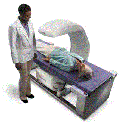
Figure 5.3-5a
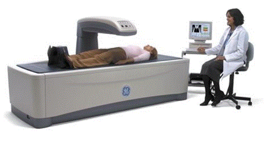
Figure 5.3-5b
Figure 5.3-5: These pictures show a Dual Energy X-ray Absorptiometry (DXA) system for Osteoporosis assessment. The table heights are fixed due to the diagnostic need for a fixed geometry. The table heights are typically 25 - 28 inches and are dictated by the needing the X-Ray source below the table for diagnostic and radiation dose considerations. Also note the equipment imaging components on the opposite side of where the patient transfers.
The subcommittee and full committee believes alternate criteria or “accessibility packages”, to strive for equivalent facilitation, will be needed to best improve independent access in the most meaningful way while adhering to the above constraints and considerations. Accessibility Packages would include accessory components, ancillary equipment, and/or siting design requirements. Accessibility packages may be able a timely, cost effective solution that may also be able to be applied to existing equipment to increase accessibility.
The following figures show some concepts of accessories to address table height that could be included an accessibility package. The accessory or installation would result in decreasing the distance between the transfer surface and the surface where the mobility device is located.
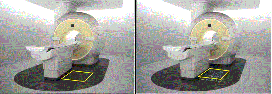
Figure 5.3-6: Flush mounted scissors lift concept (not to scale). The left side shows a flush mounted lift as in the down position while the right side shows it in its elevated position. The lift would need to appropriately sized and ramped and include edge protection.
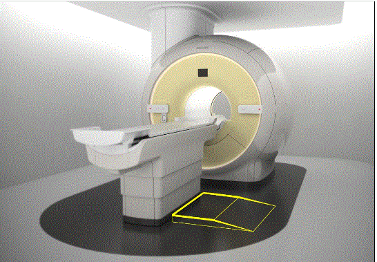
Figure 5.3-7: Elevated platform or possibly “full” floor concept (not to scale). This drawing illustrates the idea of raising the floor instead of lowering the table. This could possibly be accomplished either by a raised platform on the transfer side as shown in the drawing or by building up the floor in the entire room. If an installation is new, it may also be possible to lower the mounting surface of the equipment. An elevated platform would need to appropriately sized and ramped and include edge protection.

User Comments/Questions
Add Comment/Question