4.3.4 Knee and Toe Clearances
Adequate space without an obstruction under a design element to the floor is essential for WhMD users to approach sufficiently close in a forward direction to access equipment, controls, goods and other items, and to participate effectively in activities such as eating and work. Such clearance space is also critical when using building elements like bathroom sinks, drinking fountains, kitchen countertops, information kiosks and ATM machines.
In the current ADA-ABA standards, the clearances for knee and toe space are treated separately. But, in other countries, they are addressed together. We believe that they work together and that it would be more effective to present them in this way to avoid confusion in design application and compliance reviews. None of the standards we reviewed addressed the relationship of knee and toe clearances to anatomical and equipment reference points or landmarks. This makes it difficult to take anthropometric data and apply it to the existing standards. For example, the ADA-ABA has a sloped line indicating the depth of knee clearance at the plane of the knees and the depth somewhere above the ankles. But neither top nor bottom landmark is clearly specified. In fact, up to now, we did not have research information on the angle of the slope. Moreover, the standards do not address this design issue in practical terms. For example, the ADA-ABA has a minimum knee clearance depth of 280 mm (11 in.), but the combined knee and toe clearance depth required for an individual to bring their torso to the edge of a table or counter is not specified.
Therefore, we developed a new representation method for knee and toe clearances that can be related directly to landmarks on the body and device. Four different accommodation models were developed depicting knee and foot clearance spaces for different positions of the individual in relationship to the built element:
1. The forward-most point of the body or equipment touching a facing wall (Anterior-most point as reference);
2. The crease of the foot and lower leg in contact with the built element (Dorsal foot point as reference);
3. The forward-most point of the knee in contact with the element (Distal Knee point as reference);
4. The forward-most point of the abdomen in contact with the element (Anterior-most abdomen point as reference).
Shown below are the first (figure 4- 2) and fourth (figure 4‒3) accommodation models developed for manual wheelchair users. The shaded areas in the figures depict the envelope of the space required by a specified proportion of manual wheelchair users. These graphical representations provide information on the minimum knee and foot clearance height and depth needed in order to accommodate a specific proportion of the sample (e.g. 95%, 90%, 75%, etc.).
Each model applies to a different design scenario. The designer should select the model that is most appropriate for the task or activity to be conducted at a location and physical constraints in the environment. For example, a safe under an ATM may restrict the depth of the toe clearance, thus the first model would be used. But, in designing a desk for filling out a job application, there is no technical reason for restricting the depth of toe clearance but the leading edge of the desk should be as close to the abdomen as possible. Thus the fourth model is more appropriate.
The accommodation models are very useful for designers and product manufacturers. For simplicity, it would be good if standards had only one illustration. The following dimensions on knee and toe clearances should be used to accommodate 95% of our study sample on all four dimensions:
• Toe clearance depth: 127 mm (5 in.) maximum, measured from wall
• Toe clearance height: 356 mm (14 in.) minimum , measured from the floor
• Knee clearance height: 711 mm (28 in.) minimum, measured from the floor
• Knee clearance depth: 305 mm (12 in.) minimum, measured from the leading edge of the toe clearance or 406 (16 in.) minimum, measured from the wall if there is no separate toe clearance.
• Knee clearance depth for workstations, lunch counters and dining tables: 813 mm (32 in.) minimum, measured from the wall.
Knee clearance should not be sloped, in other words, it should be the same depth throughout.
Toe clearances at cabinets and other locations without knee clearance should be a minimum 127 mm (5 in.) high but a minimum or maximum limit is not necessary.
Overlap of toe clearance and turning clearances can be allowed.
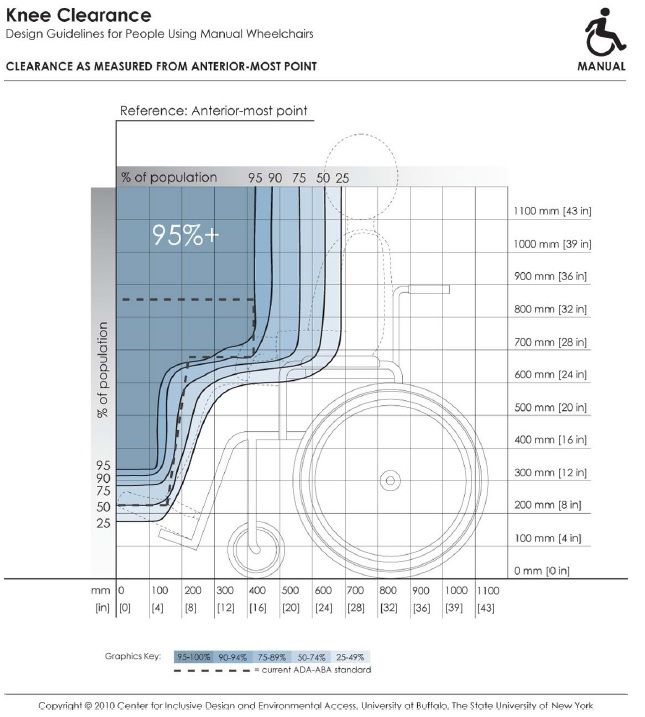
Figure 4-2: Knee and toe clearances with the forward‐most point of the body or equipment touching a facing wall (Anterior‐most point as reference)
Long Description: This depicts knee and toe clearance required by manual chair users for forward approach to elements in the built environment (e.g., light switches). It references dimensions of clearance height and depth to the forward-most point on the person or mobility device (e.g., toe, footrest). Shaded areas depict the envelope of space required by the specified percentage of people if positioned with the forward-most point touching the wall. Hence, to accommodate a particular percentage of users, the side profile of a design element (shown by dotted line) should not extend outside the corresponding shaded area.
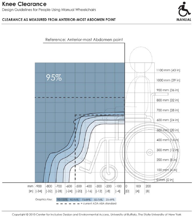
Figure 4-3: The forward‐most point of the abdomen in contact with the element (Anterior-most abdomen point as reference).
Note: In order to accommodate a specified proportion of users (e.g. 95% of the sample), the side profile of a design element shown by the dotted line should not extend beyond the corresponding envelope (e.g., the solid line marked 95%). For a given design scenario, specific dimension values for clearance height and depths can be read off the horizontal and vertical axis of the figure.
Long Description: This depicts knee and toe clearance required by manual chair users for forward approach to elements in the built environment (e.g., dining tables). It references dimensions of clearance height and depth to the forward-most abdomen point on a person. Shaded areas depict the envelope of space required by the specified percentage of people if positioned with the abdomen touching an obstruction. Hence, to accommodate a particular percentage of users, the side profile of a design element (shown by dotted line) should not extend outside the corresponding shaded area.
User Comments/Questions
Add Comment/Question