4.3 Specific Recommendations
4.3.1 Reference WhMD Users
The original ADAAG included, in its Appendix, only one reference WhMD user – a male in a manual wheelchair, while the ADA-ABA does not have any. Our results demonstrate that the WhMD population is quite diverse in terms of sizes and functional abilities and that there are significant differences between users of different types of WhMDs. Including Reference WhMD Users in the document helps designers and officials understand the basis for many design criteria in standards and also to address design issues that may not appear in the standards at all. Having a set of multiple Reference Users as opposed to one can benefit designers significantly, and our data can be used to develop many different Reference WhMD Users. We recommend that at minimum three be provided, one each for manual wheelchairs, power wheelchairs and scooters. The Reference Users should include plan and elevation drawings and have key dimensions coded with a corresponding table of values for each code showing the 5th, 25th, 50th, 75th and 95th percentile for both men and women. At minimum, the Reference WhMD Users should have data on unoccupied and occupied length and width, total occupied height, eye height and armrest height. They should also have data on accessories and equipment often attached to WhMD.
Three examples illustrate the need for the incorporation of this information in standards:
1. Occupied Height: Information on the occupied height of WhMDs is often needed in design of amusement attractions, playground equipment, museum exhibits and vehicles.
2. Lines of Sight: Currently, the ADA-ABA has requirements for clear sight lines from seating areas reserved for WhMD users. But, there are no anthropometric data provided to evaluate compliance with those requirements. Basic data on eye height is needed in the standard to help designers determine whether lines of sight are adequate.
3. Armrest height: The height of armrests on WhMD is useful for design of work stations, dining areas and other equipment and furnishings that WhMD users approach as close as possible. A Reference WhMD User could provide that information which is currently unavailable.
Tables showing results from the structural measurements of these three dimensions are provided in Appendix 2.
4.3.2 Seat Height
Seat height is an important dimension for establishing the height of built-in seating, toilet heights, tub heights, shower seat heights and other transfer related surfaces. Keeping the height of a transfer surface close to the height of a wheelchair seat reduces the effort necessary to transfer and provides a safer environment, especially in bathing and toilet rooms. However, seat height for wheelchair users can be significantly different than comfortable seat height for ambulant people. Seat heights for transfer surfaces in the ADA-ABA are 430 mm - 485 mm (17 in. - 19 in.) for water closets, shower seats and tub seats and 405 mm - 485 mm (16 in. −19 in.) for pool transfer lifts.
Our research results indicate that a range of seat heights is appropriate to accommodate the wide variety of different needs. Ranges for built elements should accommodate ambulatory individuals as well because they are the vast majority of the population. Designing only for WhMD users would cause discomfort and safety problems for too many people. Our findings show that the values of the current U.S. accessibility standards are below the mean values of each of the three WhMD user groups. The mean occupied seat heights were 495 mm (19.5 in.) for manual chair users, 538 mm (21.2 inches) for power chair users and 549 mm (21.6 in.) for scooter users. For the manual chair users, the 5th −95th percentile range was 430 mm - 566 mm (17 in. - 22.3 in.). Therefore, the current accessibility standards are more accommodating to those WhMD users with low occupied seat heights. If the goal is to accommodate the mean seat height for each of the WhMD user groups, a range of 495 mm – 549 mm (19.5 in. - 21.6 in.) is likely to be more accommodating. An application of these results could be in the design of fixed toilet heights. If the goal is to accommodate the 5th percentile occupied manual chair user seat height and the 95th percentile scooter user seat height, a range of 430 mm - 635 mm (17 in. - 25 in.) is needed. Conventional seating heights are within a ranch of 381 mm - 406 mm (15 in. −16 in.) for adults. Thus, designing even for the range of WhMD users would cause a problem for everyone else. This finding suggests that the solution to the problem should be sought in technology rather than building standards, just like it has with ergonomic office chairs. The findings could be applied to establish the range of height adjustable seat and support surfaces. Meanwhile, we recommend that the current top of the acceptable range be increased to 508 mm (20 in.) and that consideration be given to providing an assistive technology solution, a seat riser, in temporary lodging settings.
4.3.3 Clear Floor Area
Clear floor area dimensions are the basis for the minimum required size of spaces used by wheeled mobility users (e.g. platform/wheelchair lifts) and for spaces/locations that are designated for wheeled mobility users such as in seating areas of movie theatres and sports stadiums and in securement spaces of vehicles like transit buses. The clear floor area width also informs the minimum clearance width for successful passage through corridors, doorways and ramps. In some of these applications, adding more space for maneuvering may be required.
The accommodation model (Figure 4‒1) illustrates the 50th, 75th, 90th and 95th percentile values for the research results computed for occupied length and width across manual chair, powered chair and scooter users using data from our study. The 95th percentile dimension values for occupied length and breadth provide a reasonable threshold value for determining the dimensions for clear floor area length and breadth. Details about the measurement methodology and study sample can be found in (D’Souza et al., 2010b; Steinfeld et al., 2010a; 2010b).
To accommodate the 95th percentile values of both occupied width and length requires a minimum clear floor area dimensions of 786 mm x 1362 mm (31 in. x 54 in.) for manual chairs, 827 mm x 1415 mm (33 in. x 56 in.) for powered chairs, 837 mm x 1435 mm (33 in. x 56 in.) for scooters. These sets of dimensions are most applicable when the objective is to accommodate one of the dimensions, i.e., either occupied length or occupied width. For example, when designing an alcove at the side of a large open space where the length of a device must be addressed but the width is not an issue because there is plenty of room to one side.
But, one individual may have a very wide occupied length but narrow occupied width. Thus, use of results from an analysis that considers both dimensions at once when computing percentiles (a bi-variate approach) is more preferable when the goal is to accommodate 95% of the total population (see D’Souza et al., 2010b). Using this method, the minimum clear floor area dimensions recommended for accommodating 95% of the WhMD users based on a bi-variate analysis are: 820 mm x 1420 mm (32 in. x 56 in.) for manual chair users, 850 mm x 1480 mm (33.5 in. x 58 in.) for powered chair users, and 860 mm x 1440 mm (34 in. x 57 in.) for scooter users.
For applications where all of three types of mobility devices (i.e., manual chair, powered chair and scooters) need to be accommodated, the largest of the occupied length and width values across the three device categories should be used. Thus, a “universal space” to accommodate 95% of the total population would be 860 mm x 1480 mm (34 in. x 58 in.).
The implications of these dimensions are that most of the current dimensions used in the ADA-ABA are inadequate for the larger mobility device users, especially power chair and scooter users. The basic clear floor space requirement, 760 mm x 1220 mm (30 in. x 48 in.), should be increased. However, the required wheelchair seating space sizes in public assembly areas are actually about the same size as the “universal space” with one exception, the front or rear entry condition. The depth of this space should be increased from 1220 mm (48 in.) to 1480 mm (58 in.), or, to be consistent with the side entry condition, 1525 mm (60 in.) required by the ADA-ABA. While this would still make it a tight fit for maneuvering into the space for the largest users, it would only inconvenience a few people. Requiring some rear or front entry seating areas in each facility could be an alternative strategy.
Where aisles and other spaces adjoin the clear floor area, the real need for the “universal space” may be minimal. For example, the occasional very long occupied device can be accommodated without too much inconvenience to people passing by or interference with minimum egress requirements. Also, where several wheelchair seating spaces are provided at once, it is unlikely that all the occupants approach or exceed the 95th percentile in both length and width. In other words, a certain amount of overlap with other spaces and between spaces could be provided to reduce the impact on space utilization without serious consequences. Thus, in the ADA-ABA clear floor space for two devices, a lower overall width of 1676 mm (66 in.) is probably sufficient.
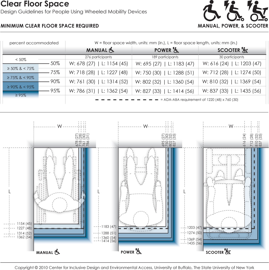
Figure 4-1: Accommodation model depicting the clear floor space for users of manual wheelchairs, powered wheelchairs, and scooters.
Long Description: This data provides the minimum dimensions for the rectangular floor area required by occupied wheeled mobility devices (i.e., with the occupant seated in their own wheeled mobility device) when stationary. Clear floor area dimensions are used for determining the size of spaces designated for wheeled mobility users (such as on buses, in movie theaters, sports stadiums). The clear floor area width dimension also informs the minimum clearance width for successful passage through corridors, doorways, and wheelchair ramps. Currently, the ADA accessibility guidelines prescribe a minimum floor area of 760 x 1220 mm (30 x 48 in.) for wheeled mobility access. Dimensions are based on length and width measurements obtained from occupied wheeled mobility devices as part of the Anthropometry of Wheeled Mobility Study. These data suggest minimum clear floor area dimensions of 786 x 1362 mm (31 x 54 in.) for manual chairs, 827 x 1414 mm (33 x 56 in.) for powered chairs, and 837 x 1435 mm (33 x 56 in.) for scooters when needing to accommodate 95% of users.
4.3.4 Knee and Toe Clearances
Adequate space without an obstruction under a design element to the floor is essential for WhMD users to approach sufficiently close in a forward direction to access equipment, controls, goods and other items, and to participate effectively in activities such as eating and work. Such clearance space is also critical when using building elements like bathroom sinks, drinking fountains, kitchen countertops, information kiosks and ATM machines.
In the current ADA-ABA standards, the clearances for knee and toe space are treated separately. But, in other countries, they are addressed together. We believe that they work together and that it would be more effective to present them in this way to avoid confusion in design application and compliance reviews. None of the standards we reviewed addressed the relationship of knee and toe clearances to anatomical and equipment reference points or landmarks. This makes it difficult to take anthropometric data and apply it to the existing standards. For example, the ADA-ABA has a sloped line indicating the depth of knee clearance at the plane of the knees and the depth somewhere above the ankles. But neither top nor bottom landmark is clearly specified. In fact, up to now, we did not have research information on the angle of the slope. Moreover, the standards do not address this design issue in practical terms. For example, the ADA-ABA has a minimum knee clearance depth of 280 mm (11 in.), but the combined knee and toe clearance depth required for an individual to bring their torso to the edge of a table or counter is not specified.
Therefore, we developed a new representation method for knee and toe clearances that can be related directly to landmarks on the body and device. Four different accommodation models were developed depicting knee and foot clearance spaces for different positions of the individual in relationship to the built element:
1. The forward-most point of the body or equipment touching a facing wall (Anterior-most point as reference);
2. The crease of the foot and lower leg in contact with the built element (Dorsal foot point as reference);
3. The forward-most point of the knee in contact with the element (Distal Knee point as reference);
4. The forward-most point of the abdomen in contact with the element (Anterior-most abdomen point as reference).
Shown below are the first (figure 4- 2) and fourth (figure 4‒3) accommodation models developed for manual wheelchair users. The shaded areas in the figures depict the envelope of the space required by a specified proportion of manual wheelchair users. These graphical representations provide information on the minimum knee and foot clearance height and depth needed in order to accommodate a specific proportion of the sample (e.g. 95%, 90%, 75%, etc.).
Each model applies to a different design scenario. The designer should select the model that is most appropriate for the task or activity to be conducted at a location and physical constraints in the environment. For example, a safe under an ATM may restrict the depth of the toe clearance, thus the first model would be used. But, in designing a desk for filling out a job application, there is no technical reason for restricting the depth of toe clearance but the leading edge of the desk should be as close to the abdomen as possible. Thus the fourth model is more appropriate.
The accommodation models are very useful for designers and product manufacturers. For simplicity, it would be good if standards had only one illustration. The following dimensions on knee and toe clearances should be used to accommodate 95% of our study sample on all four dimensions:
• Toe clearance depth: 127 mm (5 in.) maximum, measured from wall
• Toe clearance height: 356 mm (14 in.) minimum , measured from the floor
• Knee clearance height: 711 mm (28 in.) minimum, measured from the floor
• Knee clearance depth: 305 mm (12 in.) minimum, measured from the leading edge of the toe clearance or 406 (16 in.) minimum, measured from the wall if there is no separate toe clearance.
• Knee clearance depth for workstations, lunch counters and dining tables: 813 mm (32 in.) minimum, measured from the wall.
Knee clearance should not be sloped, in other words, it should be the same depth throughout.
Toe clearances at cabinets and other locations without knee clearance should be a minimum 127 mm (5 in.) high but a minimum or maximum limit is not necessary.
Overlap of toe clearance and turning clearances can be allowed.
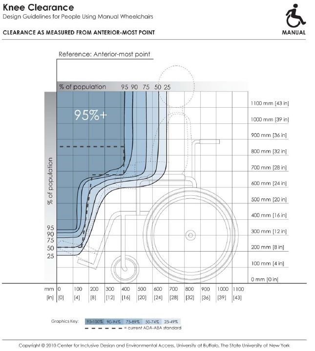
Figure 4-2: Knee and toe clearances with the forward‐most point of the body or equipment touching a facing wall (Anterior‐most point as reference)
Long Description: This depicts knee and toe clearance required by manual chair users for forward approach to elements in the built environment (e.g., light switches). It references dimensions of clearance height and depth to the forward-most point on the person or mobility device (e.g., toe, footrest). Shaded areas depict the envelope of space required by the specified percentage of people if positioned with the forward-most point touching the wall. Hence, to accommodate a particular percentage of users, the side profile of a design element (shown by dotted line) should not extend outside the corresponding shaded area.
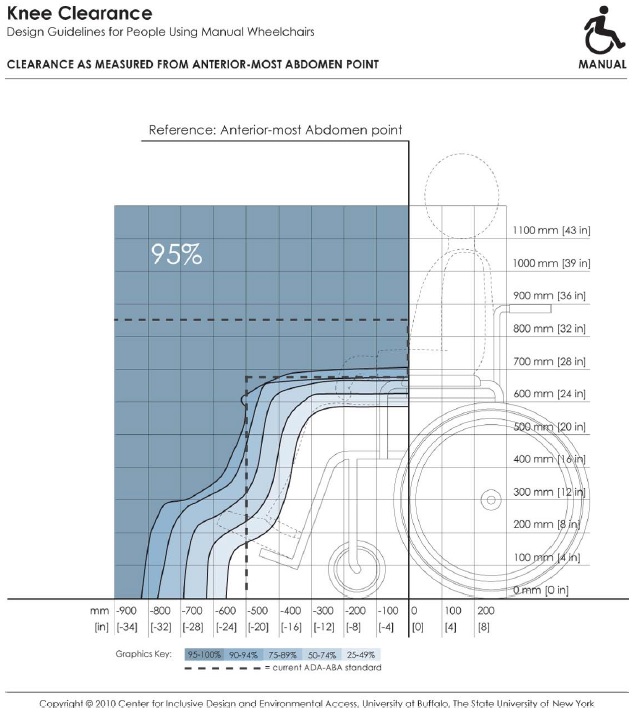
Figure 4-3: The forward‐most point of the abdomen in contact with the element (Anterior-most abdomen point as reference).
Note: In order to accommodate a specified proportion of users (e.g. 95% of the sample), the side profile of a design element shown by the dotted line should not extend beyond the corresponding envelope (e.g., the solid line marked 95%). For a given design scenario, specific dimension values for clearance height and depths can be read off the horizontal and vertical axis of the figure.
Long Description: This depicts knee and toe clearance required by manual chair users for forward approach to elements in the built environment (e.g., dining tables). It references dimensions of clearance height and depth to the forward-most abdomen point on a person. Shaded areas depict the envelope of space required by the specified percentage of people if positioned with the abdomen touching an obstruction. Hence, to accommodate a particular percentage of users, the side profile of a design element (shown by dotted line) should not extend outside the corresponding shaded area.
4.3.5 Turning clearance
The ADA-ABA Standards include requirements for a circular turning space, a T shaped turning space, a L-Turn (90-degree turn) and a U-Turn (180-degree turn) around an obstacle. In our research several turning maneuvers were studied: the 360-degree turn, the 180-degree turn, the 180-degree turn around a barrier and a 90-degree turn. In confined dead end spaces, a 360-degree turn should be used as the basis for the minimum space required since individuals often move around within small space without actually leaving it. A 180-degree turn is more appropriate as a basis for defining a minimum space bounded only on two sides and the individual has an open space to use along the axis of the turn. T shaped space is not included here because it can be derived from the 90-degree turn to establish the width of the arms of the T and the clear floor space to determine the length of each arm. The overall width should be the same in both arms. The same values should be used for the 90-degree turn and the T-turn.
The accommodation models and our recommendations are addressed individually below. In general, standards should give some guidance on where each of these turning spaces should be used. For example, the 180-degree turn around an obstruction should be used at ramp landings rather than the 180-degree unobstructed turn clearance.
4.3.5.1 90-Degree Turn
This turning clearance is applicable for exterior and interior circulation, aisles in seating areas, ramps and other locations. The width of circulation spaces should be wider to accommodate two-way traffic and egress requirements.
The mean values for scooters in our sample are in excess of the current standards. In addition, less than 80% of power and manual wheelchair users in our sample are accommodated by the standard. We recommend revising the ADA-ABA standard for 90-degree turning width to 1000 mm (39 in.) which would accommodate at least 95% of our sample. Figure 4‒4 shows the accommodation model of the minimum clear width required for the 90-degree turn.
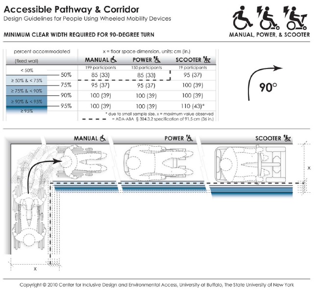
Figure 4-4: Accommodation model depicting the minimum clear width required by users of manual wheelchairs, powered wheelchairs and scooters to complete a 90-degree turn.
Long Description: This data depicts the amount of space required by users of wheeled mobility devices to perform a 90-degree turn ("L-Turn"). The bold dashed line in the table and figure indicates the current ADA requirement of a 91.5 cm (36 in.) passage width. Findings from the Anthropometry of Wheeled Mobility Study indicate that a width of at least 85 cm (33 in.) was required for 50% of the manual and power wheelchair users measured in this study to perform a 90-degree turn. A width of 100 cm (39 in.) was required in order for 95% of manual wheelchair and power chair users to complete the turn, with 95% of scooter users needing a width of at least 110 cm (43 in.) These data are based on measurements of wheeled mobility users performing 90-degree turns in a hallway, built with mock walls. The outside wall of the hallway was fixed. The other side of each leg had moveable walls. The enclosed space was incrementally increased until a user could pass through the turn successfully. The minimum space required for completing a 90-degree turn within moving or knocking down any of the walls was recorded. Use of multiple short turns was allowed in contrast to a single continuous turn.
4.3.5.2 180-degree turn
Currently, the ADA-ABA does not have a specific clearance for this type of turn. The 1525 mm (60 in.) turning space would be used instead. Our research findings for this turn apply to corridors and other circulation spaces are bounded by two parallel walls or three walls. Our findings indicated that a width of 1700 mm (67 in.) would accommodate 95% of manual and power wheelchair users and 90% of the scooter users. Accommodation of additional scooter users would increase this dimension by 18 mm (7 in.) (Figure 4‒5).
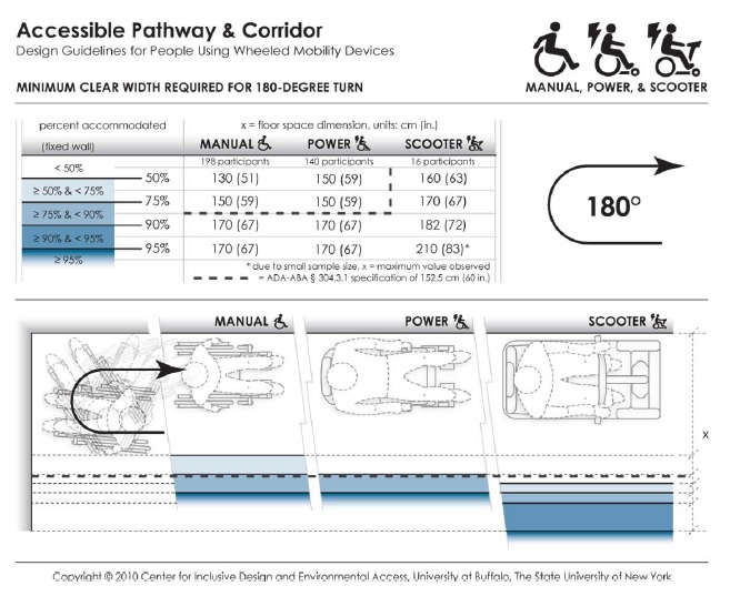
Figure 4-5: Accommodation model depicting the minimum clear width required by users of manual wheelchairs, powered chairs and scooters to complete a 180-degree turn.
Long Description: This data depicts the amount of space required by users of wheeled mobility devices to perform a 180-degree turn. The bold dashed line in the table and figure indicates the current ADA requirement of a 152.5 cm (60 in.) space for wheeled mobility users to turn around. Findings from the Anthropometry of Wheeled Mobility Study indicate that a width of at least 130 cm (51 in.) was required for 50% of the manual wheelchair users measured in this study to perform a 90-degree turn. A width of 170 cm (67 in.) was required in order for 95% of manual wheelchair and power chair users to complete the turn, with 95% of scooter users needing a width of at least 210 cm (83 in.) These data are based on measurements of wheeled mobility users performing 180-degree turns in a dead-end hallway, built with mock walls. The end wall and a second wall of the hallway were fixed. The other side of the hallway had a moveable wall. The hallway width was incrementally increased until a user could enter the space, turn around, and exit the space successfully. The minimum space required for completing 180-degree turn within moving or knocking down any of the walls was recorded. Use of multiple short turns was allowed in contrast to a single continuous turn.
4.3.5.3 180-degree turn around an obstacle
This type of turn is applicable to turning at a landing where one is reversing direction to move back along a parallel path, e.g. at the end aisles in library stacks or supermarkets, at switchback ramps or in a terminal queue. The current ADA-ABA standard for the space needed to complete maneuver is based on the width of the entry aisle and the width of the intervening obstacle, e.g. shelving. In our research, we studied the impact of keeping the depth of the turning area and the entry/egress aisle width identical. This provided the opportunity to discover if a wider aisle would lead to less required depth in the turning area. This was, in fact, the case. The accommodation model depicts the results with the condition that depth is the same as access and egress aisle width. We found that a width of 1065 mm (42 in.) for all three dimensions would accommodate more than 90% of the manual wheelchair and more than 95% of the power chair users but less than 80% of the scooter users. We recommend using this approach in future ADA-ABA standards with a minimum width of 1095 mm (43 in.) which would accommodate more than 95% of all WhMD users in the sample. This would increase the width slightly but reduce the depth of the turning area significantly. When the entry and egress aisles are less than this width, the 360-degree turn clearances should be provided at the turning area. In effect, this condition is a space bounded by three sides and requires a lot more space because WhMD users cannot cut the corner like they can with a wider aisle width (Figure 4‒6).
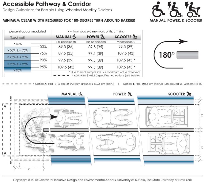
Figure 4-6: Accommodation model depicting the minimum clear width required by users of manual wheelchairs, powered wheelchairs and scooters to complete a 180-degree turn around an obstacle.
Long Description: This data depicts the amount of space required by users of wheeled mobility devices to perform a 180-degree turn ("U-Turn") around an obstruction. The bold dashed line in the table and figure indicates the current ADA requirements, which vary based on the passage width and space available at the base of the turn. Findings from the Anthropometry of Wheeled Mobility Study indicate that a uniform width of at least 89.5 cm (35 in.) was required for 50% of the manual and power wheelchair users measured in this study to perform a 180-degree turn around the obstruction. A width of 109.5 cm (43 in.) was required in order to accommodate 95% of all users. These data are based on measurements of wheeled mobility users performing 180-degree turns around an obstruction, built with mock walls. An obstruction of 11 cm (4 in.) was fixed at a central location. Three moveable walls were constructed around the central fixed wall to form a U-shaped hallway of equal passage width. The enclosed space was incrementally and uniformly increased until a user could pass through the U-turn successfully. The minimum space required for completing a 180-degree turn around an obstruction within moving or knocking down any of the walls was recorded. Use of multiple short turns was allowed in contrast to a single continuous turn.
4.3.5.4 360-degree Turn
Accommodation models for 360-degree turns have been developed for the three types of devices based on the results (e.g. Figure 4‒7). There are substantial differences between the device types. Scooters require the largest turning spaces and manual chairs the least although there are some manual chair users that required spaces as large as many power chair users. The use of the 95th percentile in the power chair findings would increase the current requirements by 575 mm (23 in.). The size of the space required for the 95th percentile of scooter users would create even larger increases. Thus, due to the potential impact, these findings require some policy decisions on who to exclude, or a new way to address this design issue.
Dimensions for 360-degree turning spaces are used to determine the minimum spaces needed for turning around in spaces with only one point of entry. To better represent these situations, we based our measurements on a square-shaped space rather than circular as the former allows WhMD users to use the corners thereby optimizing space utilization. In spaces in which turning around is not critical for usability, another basis for determining the minimum floor area can be used as in the Fair Housing Accessibility Guidelines which only require a clear floor space outside the arc of a swinging door. This strategy is also already used for elevators and toilet stalls in the ADA-ABA Guidelines. A second strategy is to provide a turning space in all covered public spaces like toilet rooms, laundries and shared kitchenettes to accommodate the 50th or 75th percentile and, in addition, require at least one of each type of space somewhere in a building to be large enough to accommodate the largest devices. For example, one companion toilet room could be required in every building that accommodates both assisted use and the largest devices while the other toilet rooms meet less space intensive requirements. The largest turning space could also be required in places where the impact of increasing turning spaces is insignificant, for example, in a lobby or outdoors. Obviously, better space planning can also be used to avoid dead end spaces entirely but that cannot be mandated in a standard.
The implications of these findings are so significant that the authors recommend starting broad discussion of options among stakeholders before a concrete proposal is made to adopt a particular strategy.
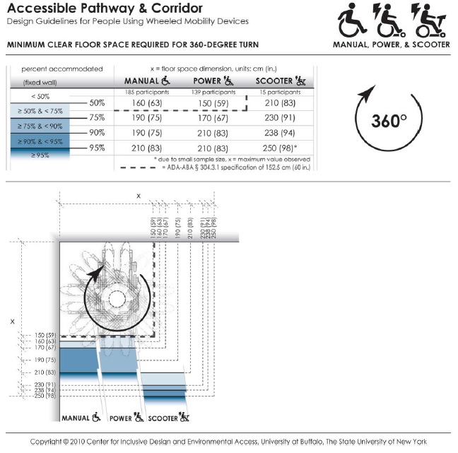
Figure 4-7: Accommodation model depicting the minimum clear space required by users of manual wheelchairs, powered chairs and scooters to complete a 360-degree turn.
Long Description: This data depicts the amount of space required by users of wheeled mobility devices to perform a 360-degree turn. The bold dashed line in the table and figure indicates the current ADA requirement of a 152.5 cm (60 in.) turn space. Findings from the Anthropometry of Wheeled Mobility Study indicate that a square space of at least 160 x 160 cm (63 in.) was required for 50% of the manual wheelchair users measured in this study to perform a 360-degree turn. A space of 210 x 210 cm (83 in.) was required in order for 95% of manual wheelchair and power chair users to complete the turn, with 95% of scooter users needing a space of at least 250 x 250 cm (98 in.) These data are based on measurements of wheeled mobility users performing 360-degree turns within an enclosed square space built with mock walls. The enclosed space was incrementally varied from a size of 130 x 130 cm (51 in.) to 250 x 250 cm (98 in.) The minimum space required for completing 360-degree turn within moving or knocking down any of the walls was recorded. Use of multiple short turns was allowed in contrast to a single continuous turn.
4.3.6 Reach Limits
Accommodation models were developed from the research findings for forward and side (lateral) reach in an empty 56 grams (2 oz.) cylinder (figure 4‒8) and a heavier 2.27 kg. (5 lb.) cylinder (see Appendix 3). In our research, only a subset of the individuals in the study sample who could lift a no-weight (56 grams or 2 oz.) cylinder above their shoulder were measured for reach limits. This insures that the accommodation models are not biased by individuals who have limited functional reaching abilities. Using these models, a designer can determine the percentage of wheeled mobility users with functional reaching ability that might be expected to reach (without a weight) to a 100 mm x 100 mm (3.9 in. x 3.9 in.) target location in space at a given height from the floor. The distance in each case can be measured from the location of the hands at the end of the reach to any number of reference points on the WhMD user’s body or chair. The corresponding percentages are color coded to differentiate regions of reach performance. Percentages of reaching ability drop significantly when the object mass is increased from 56 grams (2 oz.) to 2.27 kg. (5 lb.). With weights that weigh more than 56 grams (2 oz.), we found that 20‒25% of all three WhMD users could not reach to the same heights as to the no-weight condition. The dashed lines in the figures show the current ADA-ABA requirement which specifies a threshold value of 1220 mm (48 in.) when reaching to a target located in front of an individual at the plane of the toes or front of footrests, or “anterior most point” (for details on the development of the models, see D’Souza et al. (2009a).
The design and standards implications of the research findings are as follows:
1. Side reach access is far more preferable to forward reach access, which is quite restricted among the wheelchair user population. Targets at locations along the plane of the anterior most point will not be within the reach of a majority of wheeled mobility users, even if the maximum reach height limit were reduced to shoulder height.
2. When forward reach is the only alternative, knee clearance should be provided that allows an individual to extend their legs and front part of their wheelchair beyond the plane on which the target is located. This will allow many more individuals to reach to targets in a forward approach. For the accommodation model of forward reach, the depth of knee clearance needed to accommodate different proportions of the sample can be determined by the columns with negative offset distances and can be interpreted as the increase in ‘percent capable’ (e.g. 74% or 88% of the sample) for every 100 mm (3.9 in.) increase in available toe or knee clearance.
3. The upper height limit in the current ADA-ABA standard for unobstructed side reach, 1220 mm (48 in.) will accommodate the 99th, 95th and 96th percentile of manual wheelchair, power chair and scooter users in our sample. Thus, there is no need to change that dimension. However, a large percentage of the sub-sample of individuals who had functional reach could not safely reach to the lower limit of 380 mm (15 in.). Our results also indicate that the upper limit of reach could be increased for wheeled mobility users but this may result in limitations for people of small stature.
4. Standards developers should consider requiring either side reach access to all targets within the scope of standards or limiting front reach to locations where knee clearance is provided beyond the plane on which the target is located. The lower limit of side reach should be increased to 700 mm (28 in.). We recommend that the lower limit only be applied to controls and devices that are needed for business services (e.g. recharging station for mobile phones or wheelchairs). For long term use in work sites, power strips should be used to provide access to outlets.
5. When designing environments for tasks that require lifting objects, avoid designs that require people to reach to objects above counter height. Adjustable storage units that building occupants can customize to their own needs can improve usability. Devices like sliding shelves that reduce the length of reach tasks are another beneficial strategy.
6. Standards developers should give some consideration to the task in relationship to reach. Reach limits for storage units where lifting objects are inherent in their use, could be different than for other tasks. We believe that this issue requires discussion since there are other approaches to accommodating limited reach as noted above.
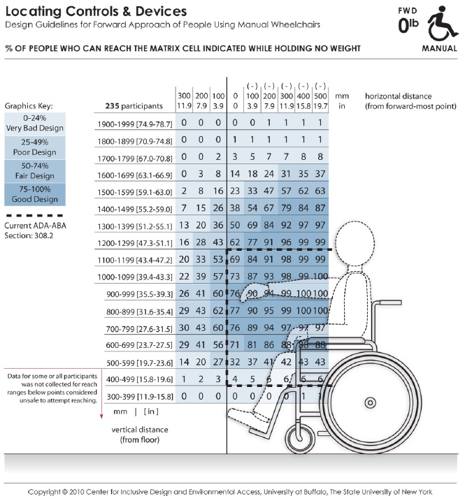
Figure 4-8: An accommodation model showing the abilities of the manual wheelchair users to complete a forward reach without lifting weight
Long Description: These data depict the reaching abilities of manual chair users represented as the percentage of users expected to reach to a target location in the forward reach direction for a given (a) height from the floor (shown the vertical axis) and (b) offset distance (shown on the horizontal axis) from the forward-most point of the person or wheelchair (e.g., toe, footrest). Horizontal distances in the positive range represent offset distance away from the body (or barrier depth) when reaching over an obstruction in relation to the forward-most point, and the negative range implying that the reach target is brought closer to the person (such as on a table with knee clearance). The percentages are color coded to differentiate regions in reach performance. The dashed lines indicate the current ADA-ABA requirement.
4.3.7 Clear Floor Space for Reaching
Clear floor space dimensions for reaching are different than for seating because they require a specific orientation to the target. This type of clear floor space should be used at light switches, wall outlets and other wall-mounted elements. Further, they can be applied to the operation of windows, access to items on a shelf or countertop, operating a telephone, automatic teller machines (ATM), information kiosks, and other places where reaching is required.
The longest reach distance from the WhMD will usually be at the approximate height and lateral direction of the shoulder joint. For forward reaches, the longest reach range will also be at the level of the shoulder unless the individual has an upper extremity impairment that affects range of motion. Reaching across the body will reduce the effective reach distance due to the reduced radius of reach. Generally, clear floor space for reaching should take into account how an individual will be oriented when reaching and seek to optimize the range of reach.
About 25% of the individuals in our sample were left-dominant, which is about double the frequency of left hand dominance in the population at large (Raymond et al., 1996). Bi-lateral access is desirable to insure adequate functional reach to targets, especially given that wheelchair users may only have functional reach and gripping ability in one arm and hand. Thus, we developed an accommodation model for clear floor space adapted for bi-lateral reach.
Accommodation models were developed for the three wheeled mobility device types, manual wheelchair users, powered chair users, and scooter users (figure 4‒9). The accommodation models provide guidance on the dimensions and location for clear floor space in relation to the reach target to accommodate:
• left and right hand users, and
• use of a forward or sideways (lateral) approach, when reaching or grasping.
For applications where all of three types of mobility devices (i.e. manual chair, powered chair and scooters) need to be accommodated, the largest of the occupied length and width values across the three device categories should be used. The models can be used to develop a right handed or left handed approach space but using the full space delineated in the model would result in a “universal approach space” that will allow all building users to perform tasks in a way that is most comfortable, i.e. using the right or left hand, and a forward or lateral approach direction. The 95th percentile values for the four measurement dimensions provide a reasonable threshold values for developing standards. As described above under Clear Floor Space, current clear floor space requirements for reaching in the ADA-ABA Standards do not accommodate the full range of contemporary wheelchairs.
The following recommendations should be implemented to specify the position of the clear floor space more appropriately than as in current standards:
1. Where reaching is critical for completing a task, e.g. an ATM machine, the universal clear floor space for reach (see accommodation model) should be provided and centered on the target. The size of the space should accommodate the 95th percentile of scooter users to accommodate the full range WhMD users.
2. For all other reach tasks, a square clear floor space, 1430 mm x 1430 mm (56 x 56 in.) should be provided, centered on the target. This will allow almost all device users to position themselves close to the target using either a front or a side reach and enough leeway for most device users to align their shoulder close to an axis on the target. But, it does not optimize for handedness.
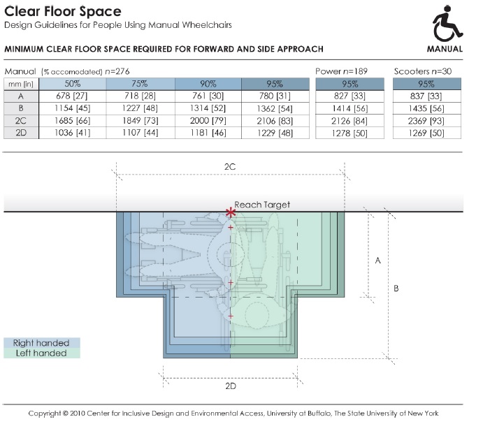
Figure 4-9: Accommodation model depicting the dimensions and positioning of the clear floor space required by manual wheelchair, powered chair, and scooter users when using either the right or left hand, for both forward and lateral reach.
Long Description: This data depicts the amount of clear floor area required by persons using wheeled mobility devices when performing a forward or side reach to a target location (e.g., reaching to a light switch on the wall) with either the right or left hand. The accompanying table provides dimensions values for clear floor area to accommodate 95% of manual chair (n=276), power chair (n=189), and scooter (n=30) users that were measured as part of the Anthropometry of Wheeled Mobility study. The dimensions of clear floor area are based on four anthropometry dimensions. These dimensions are: (A) occupied width, the horizontal distance between the side-most (lateral-most) points of the wheelchair or occupant on the right and left side; (B) occupied length, the horizontal distance from the front-most (anterior-most) point of the wheelchair or occupant to the rear-most (posterior-most) point of the wheelchair or occupant; (C)the horizontal distance from the reaching shoulder to the front-most (anterior-most) point of the wheelchair or occupant; (D) the horizontal distance from the reaching shoulder to the side-most (lateral-most) point on the opposite (contra-lateral) side of the wheelchair or occupant.
Although not specified in the ADA-ABA, the position of the clear floor space for reach in relationship to the target has been interpreted to be centered on the target. Centering, however, reduces functional reaching ability since the shortest reach is on an axis through the shoulder joint at a 90 or 180-degree reach angle. Centering requires a longer reach across the body. The universal clear floor space for reach, shown in the figure above, is designed to accommodate bilateral reach, thus it takes the offset of shoulder point to the lateral and anterior most points of the clear floor area into account and does not require a cross body reach.
To optimize for handedness using only enough space for a forward reach or side reach, the clear floor space has to be offset from either the lateral most edge of the space (front reach) or the anterior most edge of the space (side reach):
1. Front reach: Typically, the shoulder joint is about 175 mm (7 in.) inboard from the extreme lateral most point of occupied WhMD. This offset should be used for locating the clear floor space in relationship to the target. This means that the clear floor space would be offset, from the target, a distance of 175 mm (7 in.) to the right for a right-handed approach and 175 mm (7 in.) to the left for a left-handed approach.
2. Side reach: The anterior most edge of the clear floor space needs to be offset to one side of the target so that the shoulder is aligned with the reach target or slightly behind it. Offsetting the anterior most edge of the space by 1193 mm (45 in.) from the target will accommodate the 95th percentile of scooter users and, thus, provide sufficient room for everyone else to optimize their reach.
Note that using the offsets above is not feasible with the current ADA-ABA standard of 760 mm (30 in.) x 1220 mm (48 in.).
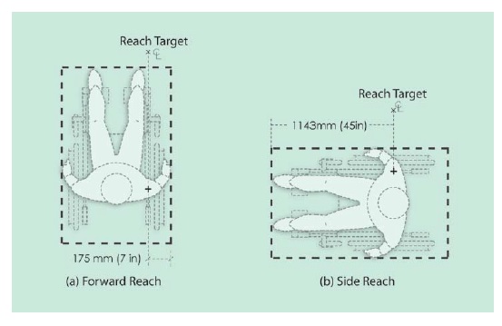
Figure 4-10: Offsets required when positioning the clear floor space in relation to the reach target in (a) forward reach, and (b) side reach.
Long Description: The figure shows two plan views of occupied WhMD, one for lateral and one for forward reach, with the target of reach positioned on axis with the shoulder joint of the device user. The forward reach plan shows the target offset 175 mm (7 in.) from the outside edge of the occupied device and the side reach plan shows the target offset 1193 mm (45 in.) from the anterior most point of the occupied device.
4.3.8 Operating forces
Operating forces are applied with a wide variety of grip forms (see Steinfeld, 1990). In this research we measured performance using three common grips – a power grip, lateral pinch and thumb-forefinger pinch grips. From these data, we can only make some broad conclusions for design and standards based on a large sample of people with relatively severe disabilities.
Designers should reduce the need for high precision grip postures and/or pinch forces given the lack of finger dexterity, motor control or pinching capabilities of persons with disabilities. This can be achieved by designs that allow operation using alternate grip configurations such as a flat hand, fist or a more convenient power grip or hook grip. Broader handles and larger gripping surface areas facilitate stronger grips.
When a precision pinch grip is required, a lateral pinch is recommended over a thumb-forefinger tip pinch grip because a lateral pinch grip provides a larger finger contact surface; the grip strength capabilities of our sample was higher for lateral pinch grip as compared thumb-forefinger pinch grip. Individuals with limited finger dexterity and strength are also more likely to be capable of forming this grip.
Use of operable parts that require fine grips preferably should not require exertion of lateral pinch grip forces in excess of 2 lbf (9 N) to accommodate the vast majority of WhMD users having at least some grasping capability. For other types of operable parts, the upper limit for operating force should be retained at a maximum of 5 lbf (22 N) to accommodate 95% of the sample.
Further, tasks and products that require operation of controls or object grasping should allow for both right and lefthanded operation, given that more than 25% of wheeled mobility device users in this study were lefthand dominant. Adequate clear floor space should be provided to access controls and switches from either the left or the right (see previous description of ‘Clear Floor Space for Reaching’).
A large proportion of wheeled mobility device users possess functional capabilities in only one hand. Hand-operated products and environmental features for use by the general public should be designed acknowledging that grip strength is significantly affected by gender, age and disability, and that a sizeable proportion of WhMD users (approx. 12% in our sample) have very limited or no grasping ability.
Grip strength data from our study can help designers employ more inclusive design criteria when developing new designs, as well as identify tasks that require pinch grip force exertion that exceed the capabilities of most users and need to be redesigned possibly through use of technological interventions and assistive devices. For example, many drawers or cabinets require tight pinching to open but adding a more ergonomically designed handle and rollers to the bottom of the drawer allows it to open with ease.
The ADA-ABA standards currently require operation with only one hand and without “tight grasping, pinching or twisting of the wrist”. This is a major step toward reducing demands on people with limitations of grip. However, the standards do not require left and right hand operation, and the maximum operating force allowed substantially exceeds the abilities of a large number of individuals in our sample for objects requiring a fine grip. Moreover, the standards preclude the use of a pinch grip, which is desirable to people who are able to use it effectively. Not allowing such grips at all may create usability problems for even more building users than it helps.
Our findings suggest developing a more detailed approach to grips and grip forces in the standards. This should include:
• Identifying maximum operating force requirements based on the types of grips and forces exerted.
• For small controls and hardware that normally would be operated with pinch grips, the maximum operating force should be 2 lbf (9 N).
• For larger controls and hardware that can be operated with a power grip, the maximum force requirements could be retained at 5 lbf (22 N) bearing in mind that this still does not address the needs of many WhMD users having very limited or no grasping ability.
• The 5 lbf (22.2 N) maximum force could be retained for operating forces for opening doors. This limit was based on the limitations of door closer technology.
• Developing specific requirements for alternative gripping options without precluding pinch grips, e.g. flat hand, knuckle push, based on existing research on hand anthropometry (e.g. Steinfeld, 1990)
• Retaining the requirement for use by only one hand.
• Utilizing standard terminology from anthropometry in reference to grip forms; the standards could list the types of grips and movements, including alternatives to standard grip forms that would be allowed. Information of this type is available from a previous Access Board study (Steinfeld, 1990; Steinfeld and Mullick, 1990).
Improving standards related to operating forces requires a careful examination of the availability of products that would be accessible to this population and the cost implications of new requirements. This would identify the limits to feasible improvements to the standards and may require adjusting the force limits to address feasible implementation.
4.3.9 Doorway Design
We did not obtain quantitative data on performance in our door use research. Thus there are no accommodation models for this topic. The results of the door trials identify relationships between structural anthropometry and identify needed modifications to current requirements.
The results of the door maneuvering studies confirmed the importance of many common accessibility code requirements. They also demonstrated a need to make some improvements to standards to provide access for the broad population of wheeled mobility users. The implications of the research findings are summarized below:
A wider clear opening than current ADA-ABA standards 815 mm (32 in.) would improve usability. Adopting a clear opening width of 860 mm (34 in.) would accommodate the widest occupied devices in our sample. This would also be small enough to allow a 91 cm (36 in.) door leaf, a size that is already used extensively for accessibility and fire safety. Consideration should be given to aligning U.S. requirements with the metric system. For example, a 90 cm door is slightly smaller than a 91 cm door but is standard elsewhere in the world and would accommodate our entire sample.
The very wide door that was tested 1041 mm (41 in.) clear opening did not increase the difficulty of using doors. The findings demonstrate that wider doors are better for accessibility and there is no need to put an upper limit on the size of doors in regulations at this time, although doors wider than this could pose some problems.
The lack of differences between the findings for the passage task on the pull sides of Doors 1, 800 mm (31.5 in.) latch clearance, and Door 2, 406 mm (16 in.) latch clearance, demonstrate that an 457 mm (18 in.) clearance required in recessed doors is acceptable although we do not have data to demonstrate whether the 305 mm (12 in.) latch clearance on other doors is satisfactory. In historic preservation, some allowances should be made for difficult renovation issues like the recess in Door 3 where the structure of the building would not only make adjusting the recess extremely difficult and costly but also would also impact its historic character.
Closers are not necessarily bad for accessibility. In fact, they reduce the difficulty of the most difficult maneuvering tasks, i.e. closing maneuver and closing tasks. Their impact on passage through the door indicates that they must be set to the lowest operating force possible to insure that they accommodate the broadest population.
Since the closing maneuver is the most difficult aspect of door use for wheelchair users, development of a low cost electromechanical closer that would not increase opening force would benefit wheelchair users significantly. It should have microprocessor control that would activate the closer only when a door is closing. When opened, a presence sensor could activate the closing cycle when an individual passed through the door.
Automating frequently used doors that are kept closed and require closers will increase accessibility substantially, especially on exterior doors where the operating forces are higher to conserve energy and insure positive latching. Requiring at least one automated door at primary entries would be highly desirable. This would increase usability for more than 10% of the wheelchair users in our sample and have multiple benefits for all building users: eliminating difficulty using the latch, enabling the opening maneuver, and eliminating difficulty closing the door. In addition, with proper placement of an activator to open the door, it eliminates the need for a latch side clearance.
User Comments/Questions
Add Comment/Question