2019 California Standards for Accessible Design Guide (effective January 1, 2020 with July 1, 2021 amendments)
11B-809 Residential dwelling units
11B-809.1 General.
When located within public housing facilities, residential dwelling units shall comply with Section 11B-809. Residential dwelling units required to provide mobility features shall comply with Sections 11B-809.2 through 11B-809.4. Residential dwelling units required to provide communication features shall comply with Section 11B-809.5.
[2010 ADA Standards] 809.1 General. Residential dwelling units shall comply with 809. Residential dwelling units required to provide mobility features shall comply with 809.2 through 809.4. Residential dwelling units required to provide communication features shall comply with 809.5.
11B-809.2 Accessible routes.
Accessible routes complying with Division 4 shall be provided within residential dwelling units in accordance with Section 11B-809.2.
Exception: Accessible routes shall not be required to or within unfinished attics or unfinished basements.
11B-809.2.1 Location.
At least one accessible route shall connect all spaces and elements which are a part of the residential dwelling unit. Where only one accessible route is provided, it shall not pass through bathrooms, closets, or similar spaces.
11B-809.2.2 Turning space.
All rooms served by an accessible route shall provide a turning space complying with Section 11B-304.
Exception: Turning space shall not be required in exterior spaces 30 inches (762 mm) maximum in depth or width.

11B-809.3 Kitchen.
Where a kitchen is provided, it shall comply with Section 11B-804.
11B-809.4 Toilet facilities and bathing facilities.
At least one bathroom shall comply with Section 11B-603. No fewer than one of each type of fixture provided within the bathroom shall comply with applicable requirements of Sections 11B-603 through 11B-610. Toilet and bathing fixtures required to comply with Sections 11B-603 through 11B-610 shall be located in the same bathroom or toilet and bathing area, such that travel between fixtures does not require travel between other parts of the residential dwelling unit.

11B-809.4.1 Subsequent bathrooms.
In residential dwelling units with more than one bathroom, when a bathtub is installed in the first bathroom in compliance with Section 11B-809.4 and a shower compartment is provided in a subsequent bathroom, at least one shower compartment shall comply with Section 11B-608.
ETA Editor's Note
The requirement for an accessible shower at subsequent bathrooms prescribed by CBC 11B-809.4.1 is not required by 2010 ADA Standards.
11B-809.5 Residential dwelling units with communication features.
Residential dwelling units required to provide communication features shall comply with Section 11B-809.5.
11B-809.5.1 Building fire alarm system.
Where a building fire alarm system is provided, the system wiring shall be extended to a point within the residential dwelling unit in the vicinity of the residential dwelling unit smoke detection system.
11B-809.5.1.1 Alarm appliances.
Where alarm appliances are provided within a residential dwelling unit as part of the building fire alarm system, they shall comply with Chapter 9, Section 907.5.2.3.3.
[2010 ADA Standards] 809.5.1.1 Alarm Appliances. Where alarm appliances are provided within a residential dwelling unit as part of the building fire alarm system, they shall comply with 702.
11B-809.5.1.2 Activation.
All visible alarm appliances provided within the residential dwelling unit for building fire alarm notification shall be activated upon activation of the building fire alarm in the portion of the building containing the residential dwelling unit.
11B-809.5.2 Residential dwelling unit smoke detection system and carbon monoxide detection system. Residential dwelling unit smoke detection systems shall comply with Chapter 9, Section 907.2.11. Residential dwelling unit carbon monoxide detection systems shall comply with Chapter 9, Section 915.
ETA Editor's Note
The lengthy California Building Code Chapter 9, Section 907.2.11 referenced above is not adopted by Division of the State Architect - Access Compliance (DSA-AC), and is not included in this Guide. To see this Section, consult California Code of Regulations, Title 24, Part 2 - 2019 California Building Code (2019 CBC), available for purchase from International Code Council (http://www.iccsafe.org).
[2010 ADA Standards] 809.5.2 Residential Dwelling Unit Smoke Detection System. Residential dwelling unit smoke detection systems shall comply with NFPA 72 (1999 or 2002 edition) (incorporated by reference, see "Referenced Standards" in Chapter 1).
11B-809.5.2.1 Activation.
All visible alarm appliances provided within the residential dwelling unit for smoke detection notification shall be activated upon smoke detection. All visible alarm appliances provided within the residential dwelling unit for carbon monoxide detection notification shall be activated upon carbon monoxide detection.
[2010 ADA Standards] 809.5.2.1 Activation. All visible alarm appliances provided within the residential dwelling unit for smoke detection notification shall be activated upon smoke detection.
11B-809.5.3 Interconnection.
The same visible alarm appliances shall be permitted to provide notification of residential dwelling unit smoke detection, building fire alarm activation, and carbon monoxide detection.
[2010 ADA Standards] 809.5.3 Interconnection. The same visible alarm appliances shall be permitted to provide notification of residential dwelling unit smoke detection and building fire alarm activation.
11B-809.5.4 Prohibited use.
Visible alarm appliances used to indicate residential dwelling unit smoke detection, carbon monoxide detection, or building fire alarm activation shall not be used for any other purpose within the residential dwelling unit.
[2010 ADA Standards] 809.5.4 Prohibited Use. Visible alarm appliances used to indicate residential dwelling unit smoke detection or building fire alarm activation shall not be used for any other purpose within the residential dwelling unit.
11B-809.5.5 Residential dwelling unit primary entrance.
Communication features shall be provided at the residential dwelling unit primary entrance complying with Section 11B-809.5.5.
11B-809.5.5.1 Notification.
A hard-wired electric doorbell shall be provided. A button or switch shall be provided outside the residential dwelling unit primary entrance. Activation of the button or switch shall initiate an audible tone and visible signal within the residential dwelling unit. Where visible doorbell signals are located in sleeping areas, they shall have controls to deactivate the signal.
11B-809.5.5.2 Identification.
A means for visually identifying a visitor without opening the residential dwelling unit entry door shall be provided and shall allow for a minimum 180 degree range of view.

11B-809.5.6 Site, building, or floor entrance.
Where a system, including a closed-circuit system, permitting voice communication between a visitor and the occupant of the residential dwelling unit is provided, the system shall comply with Section 11B-708.4.
11B-809.6 Residential dwelling units with adaptable features.
Multi-family residential dwelling units with adaptable features shall comply with Sections 11B-809.7 through 11B-809.12.
11B-809.7 Accessible routes.
An accessible route shall be provided complying with Section 11B-809.7. The accessible route shall pass through the primary entry door, through all rooms within the dwelling unit and exterior decks and balconies. The accessible route shall adjoin or overlap clear floor spaces and connect all exterior doors.
Exceptions:
-
An accessible route shall not be required from the interior of the unit into a basement.
-
An accessible route to a garage shall comply with Section 11B-208.3.3.
-
An accessible route shall not be required to rooms or spaces not located on the primary entry level of a multistory dwelling unit.
11B-809.7.1 Width.
The clear width for the accessible route shall be 36 inches (914 mm) minimum.
Exception: The clear width shall be permitted to be reduced to 32 inches (813 mm) minimum at doors.
11B-809.7.2 Changes in level.
Changes in level shall comply with Sections 11B-303.2 and 11B-303.3. Ramps complying with Section 11B-405, elevators complying with Section 11B-407 or platform lifts complying with Section 11B-410 shall be provided where changes in level exceed 1/2 inch (12.7 mm) high.
11B-809.8 Doors.
Primary entry doors, required exit doors, secondary exterior doors and interior doors intended for user passage shall comply with this section and Section 11B-404.2. Doors to small mechanical closets specifically dedicated to furnaces or hot water heaters shall not be required to comply with this section.
Exceptions: At primary entry doors, required exit doors, secondary exit doors and interior doors the following exceptions apply:
1. The floor or landing at primary entry doors, required exit doors, and secondary exit doors where a change in elevation occurs between the interior and the exterior surface of the floor or landing, shall comply with the following:
a. Exterior landings of impervious construction (e.g., concrete, brick, flagstone) serving primary entry doors and required exit doors are limited to not more than 1/2 inch (12.7 mm) of change in height between floor surfaces. Changes in level shall comply with Section 11B-809.7.2.
b. Exterior landings of pervious construction (e.g., wood decking with spaces) shall be the same level as the interior landing, except that secondary exterior doors may have no more than 1/2 inch (12.7 mm) of change in height between floor surfaces. Changes in level shall comply with Section 11B-809.7.2.
c. Secondary exterior doors onto decks, patios, or balcony surfaces constructed of impervious materials (e.g., concrete, brick, flagstone) may have a maximum change in height from the interior landing of 4 inches (102 mm). Changes in height greater than 1/2 inch (12.7 mm) shall be accomplished by means of a ramp complying with Section 11B-405 or by means of a platform constructed to the level of the floor as illustrated in Figure 11B-809.8 (c).
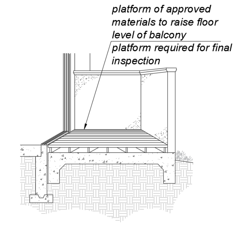
FIGURE 11B-809.8 Ex. 1(c)
PLATFORM AT SECONDARY EXTERIOR DOOR.
d. Secondary exterior doors onto decks, patios or balcony surfaces constructed of impervious materials (e.g., concrete, brick, flagstone) may have a maximum change in height from the interior landing of 1 inch (25 mm), provided a ramp with a maximum slope of 1:8 is permanently installed as illustrated in Figure 11B-809.8 (d).
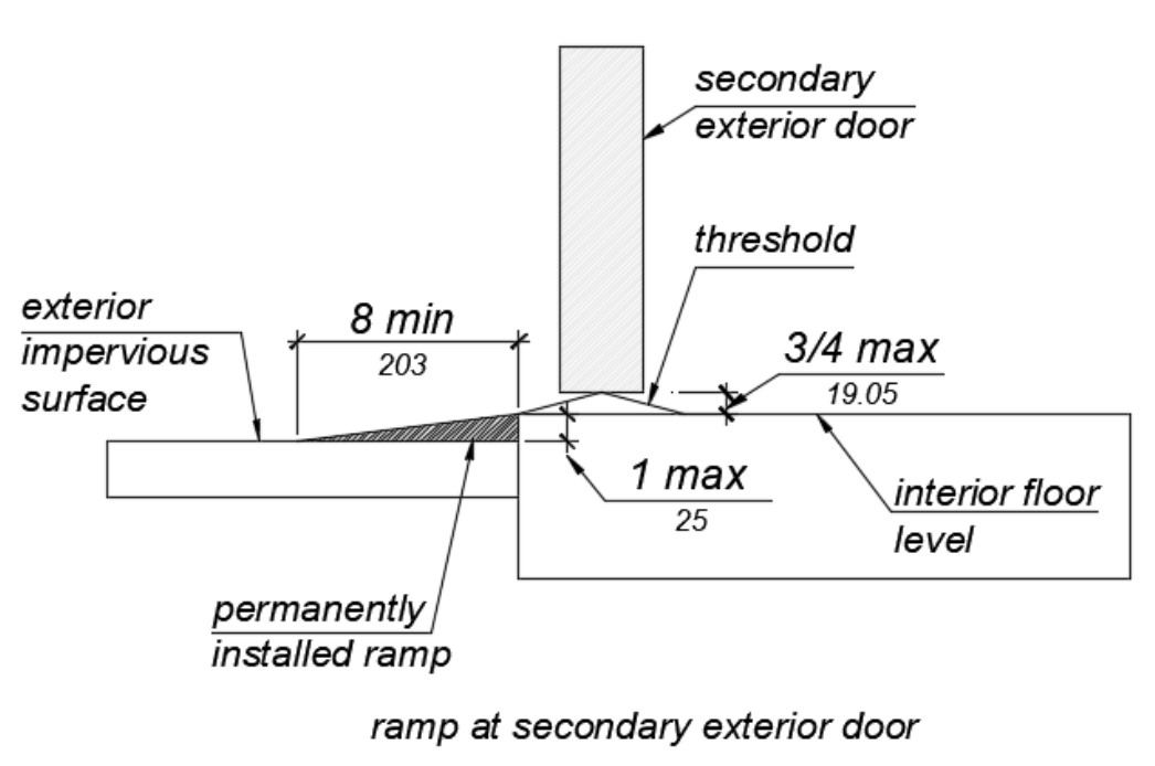
FIGURE 11B-809.8 Ex. 1(d)
RAMP AT SECONDARY EXTERIOR DOOR.
11B-809.8.1 Door Thresholds.
Secondary exterior door thresholds, including sliding door tracks, shall be 3/4 inch (19.1 mm) high maximum with a 1:2 maximum slope.
11B-809.8.2 Door opening force.
The opening force for primary entry exterior doors and secondary exterior doors shall be 8.5 pounds (38 N) maximum.
11B-809.8.3 Door maneuvering clearance.
-
At the dwelling unit side of the primary entry doors, secondary exterior doors, and required exit doors maneuvering clearances shall be 44 inches (1118 mm) minimum in length measured perpendicular to the face of the door in the closed position. The width of the maneuvering clearance shall extend 18 inches (457 mm) beyond the strike edge at the pull side of the door.
-
At interior doors maneuvering clearances shall be 42 inches (1067 mm) minimum in length on the both (sic) sides of the door measured perpendicular to the face of the door in the closed position. A 39 inch (991 mm) minimum length is allowed at interior doors when a clear opening width of 34 inches (864 mm) minimum is provided. The width of the maneuvering clearance shall extend 18 inches (457 mm) beyond the strike edge at the pull side of the door.
11B-809.8.4 Door signal devices.
Every primary entrance to a residential dwelling unit with adaptable features shall be provided with a door buzzer, bell, chime or equivalent. The activating mechanism shall be mounted 48 inches (1219 mm) maximum above the floor and connected to permanent wiring.
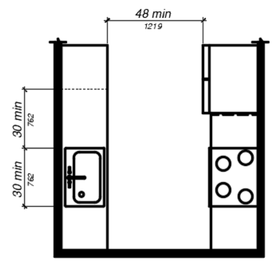
11B-809.9 Kitchens.
Kitchens shall be on an accessible route and shall comply with this section.
11B-809.9.1 Clear floor space.
Clear floor spaces 30 inches (762 mm) by 48 inches (1219 mm), with centerlines aligned with the centerline of the work surface, appliance, sink or fixture, shall be provided in the following locations:
-
For a parallel approach at the range.
-
For parallel or forward approach at a cooktop.
-
For a parallel or forward approach to the sink and to the work surface required by Sections 11B-809.9.3 and 11B-809.9.4.
-
For a parallel or forward approach to all other fixtures or appliances.
11B-809.9.2 Clear width.
Kitchens shall have a minimum clear width measured between any cabinet, work surface or the face of any appliance (excluding handles and controls) and the opposing cabinet, work surface, appliance or wall as follows:
a. U-shaped kitchens, designed with parallel approach at a sink, range, cooktop or other fixtures and appliances located at the base of the U without knee and toe clearance, shall provide a clear width of 60 inches (1524 mm) minimum.
b. U-shaped kitchens, with a cooktop, sink or work surface located at the base of the U, that provides knee and toe space complying Sections 11B-809.9.3 and 11B-809.9.4 to allow for a forward approach, shall provide a clear width of 48 inches (1219 mm) minimum.
c. All other kitchen designs shall provide a clear width of 48 inches (1219 mm) minimum.
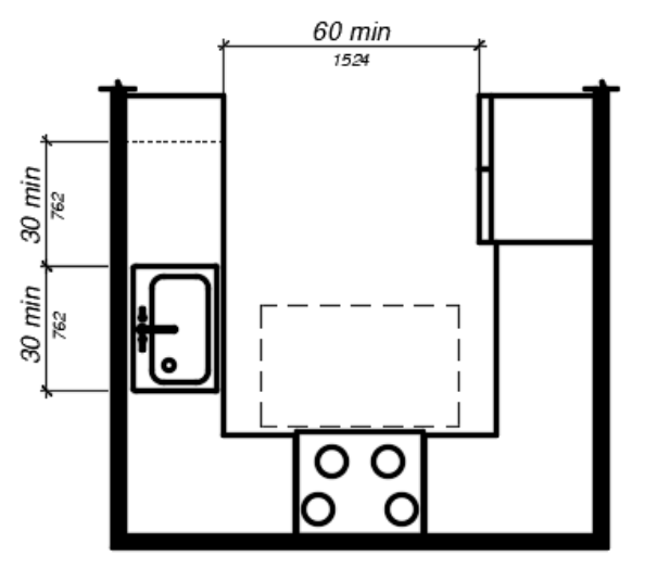
(a)
"U" shaped kitchen with parallel approach at range
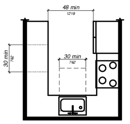
(b)
"U" shaped kitchen with forward approach at sink
(c)
other kitchen designs
FIGURE 11B-809.9.2
CLEAR WIDTH AT KITCHENS.
11B-809.9.3 Removable base cabinets.
Knee and toe space complying with Section 11B-306 shall be provided at sinks and work surfaces required to comply with Section 11B-809.9.4.
Exception: Removable base cabinets shall be permitted under sinks and work surfaces provided that all of the following conditions are met:
a) base cabinets can be removed without the use of specialized tools or knowledge;
b) the finish floor extends under the base cabinet; and
c) the walls behind and surrounding the base cabinets are finished.
11B-809.9.4 Work surfaces.
Work surfaces shall be 36 inches (914 mm) maximum above the finish floor with minimum lengths at the following locations as required by this section:
-
Linear length of 30 inches (762 mm) minimum for installation of a sink.
-
Linear length of 30 inches (762 mm) minimum for work surfaces.
-
A sink and work surface in a single integral unit 60 inches (1524 mm) minimum in length, is permitted.
11B-809.9.5 Lower shelving.
Lower shelving and/or drawer space shall be provided at a height of 48 inches (1219 mm) maximum above the finish floor.
11B-809.9.6 Controls.
Controls for faucets shall comply with Section 11B-309.1. Hand-operated metering faucets shall remain open for 10 seconds minimum.
11B-809.9.7 Exposed pipes and surfaces.
Exposed water supply and drain pipes under sinks and lavatories shall comply with Section 11B-606.5.
11B-809.10.1 General.
All toilet and bathing rooms on an accessible route within residential dwelling units with adaptable features shall comply with Sections 11B-809.7, 11B-809.8, 11B-809.10.6.4, 11B-809.10.7.3 and 11B-809.12.
11B-809.10.2 Number of complying bathing rooms and fixtures.
One bathing room and one fixture of each type within the dwelling unit shall be designed to comply with the following:
-
Maneuvering space in toilet, bathing and shower rooms shall comply with Section 11B-809.10.4.
-
Bathtubs complying with Section 11B-809.10.5.
-
Showers complying with Section 11B-809.10.6.
-
Water closets complying with Section 11B-809.10.7.
-
Lavatories, vanities, mirrors and towel bars complying with Section 11B-809.10.8. When two or more lavatories are provided, at least one shall comply with Section 11B-809.10.8.
-
Where both a tub and shower are provided in the bathroom, at least one shall be made accessible. Where two or more bathrooms are provided, when a bathtub is installed in the first bathroom in compliance with Section 11B-809.10.5 and a shower compartment is provided in a subsequent bathroom, at least one shower compartment shall comply with Section 11B-809.10.6.
11B-809.10.3 Powder rooms.
Powder rooms shall be designed to comply with Sections 11B-809.7, 11B-809.8, 11B-809.10.5.2, 11B-809.10.6.4, 11B-809.10.7.3, and 11B-809.12. When the powder room is the only toilet facility located on an accessible level it shall, in addition, comply with Sections 11B-809.10.4, 11B-809.10.7 and 11B-809.10.8.
11B-809.10.4 Sufficient maneuvering space.
Where doors swing into the toilet and bathing or powder rooms required to comply with Section 11B-809.10, a clear maneuvering space of 30 (762 mm) inches by 48 inches (1219 mm) minimum shall be provided outside the arc of the door swing. The clear maneuvering space shall be permitted to include knee and toe clearance under bathroom fixtures. Doors shall be permitted to encroach into the clear floor space or clearance for fixtures where clear maneuvering space is provided outside the arc of the door swing. A turning space is not required within the room.
11B-809.10.5 Bathtubs.
Bathtubs required by Section 11B-809.10 shall comply with this section.
11B-809.10.5.1 Clear floor space.
A clear floor space 30 inches (762 mm) minimum by 48 inches (1219 mm) minimum shall be located with the long edge of the clear floor space parallel to the side of the bathtub or bathtub-shower combination. Controls shall be located on the wall at the foot of the bathtub. The edge of the clear floor space shall be flush with the control wall surface. The area under a lavatory, located at the control end of the tub, shall be permitted to encroach on the clear floor space provided the lavatory is 19 inches (483 mm) maximum in depth, and knee and toe clearance complying with Section 11B-306 is provided. Cabinets under lavatories and toilets shall not encroach on the clear floor space.
11B-809.10.5.2 Reinforcement for grab bars.
Reinforcement for grabs bars shall comply with the following:
1. Where bathtubs are installed without surrounding walls reinforcement shall be provided for floor-mounted grab bars.
2. Where bathtubs are installed with surrounding walls, grab bar reinforcement shall be installed as follows:
a. At the control end wall and head end wall, between 30 inches (762 mm) maximum to 38 inches (965 mm) minimum above the finish floor, extending 28 inches (711 mm) minimum from the front edge of the bathtub to the back wall of the bathtub. The grab bar reinforcement shall be 8 inches (203 mm) minimum in height.
b. At the back wall, from 5 inches (127 mm) maximum above the bathtub rim to 38 inches (965 mm) minimum above the finish floor. Grab bar backing shall be installed horizontally to permit the installation of a 48-inch (1219 mm) grab bar with each end 6 inches (152 mm) maximum from the end walls of the bathtub.
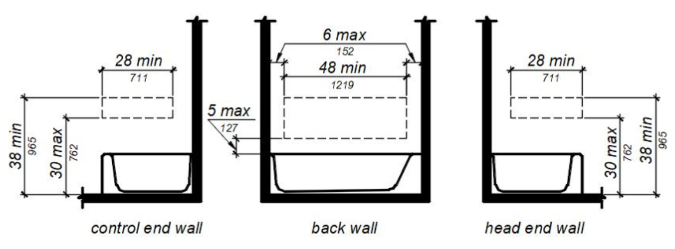
FIGURE 11B-809.10.5.2 REINFORCEMENT FOR GRAB BARS.
11B-809.10.5.3 Controls.
Controls and operating mechanisms shall comply with Section 11B-309.4.
Exception: Shower spray units are not required in bathtubs.
11B-809.10.5.4 Bathtub enclosures.
Doors and panels of bathtub enclosures shall be constructed from approved, shatter-resistant materials. Hinged doors shall open outward. Glazing used in doors and panels of bathtub enclosures shall be fully tempered, laminated safety glass or approved plastic. When glass is used, it shall be 1/8 inch (3.2 mm) thick minimum when fully tempered, or 1/4 inch (6.4 mm) thick minimum when laminated, and shall pass the test requirements of this part, Chapter 24 Glass and Glazing. Plastics used in doors and panels of bathtub enclosures shall be of a shatter-resistant type.
11B-809.10.6 Showers.
Showers required by Section 11B-809.10 shall comply with this section.
11B-809.10.6.1 Size.
When one or more shower stalls are provided within the same dwelling unit, as least one shower stall shall comply with one of the following:
-
A transfer type shower compartment 36 inches (914 mm) wide by 36 inches (914 mm) deep with an entrance opening 36 inches (914 mm) complying with Section 11B-608.1 or;
-
A shower stall 30 inches (762 mm) deep minimum by 60 inches (1524 mm) wide minimum with an entrance opening 60 inches (1524 mm) minimum. A water closet shall be permitted to project 12 inches (305 mm) maximum into the opening provided that 36 inches (914 mm) minimum clear space is maintained between the water closet and the shower wall as illustrated in Figure 11B-809.10.6.1 or;
-
A shower stall 36 inches (914 mm) deep by 60 inches (1524 mm) wide minimum with an entrance 36 inches (914 mm) minimum when a wall is installed on the opening side.
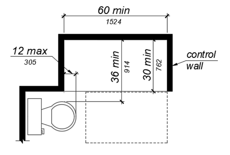
FIGURE 11B-809.10.6.1 SHOWERS.
11B-809.10.6.2 Slope.
The slope of the shower floor shall be 1/2 inch (12.7 mm) per foot maximum in any direction and shall slope to a drain. The floor surfaces shall be of Carborundum, grit-faced tile or of material providing equivalent slip resistance.
11B-809.10.6.3 Floor space.
A clear maneuvering space 30 inches (762 mm) wide minimum by 48 inches (1219 mm) minimum in length shall be located outside the shower, with the width flush with the control wall and the length parallel to the length of the shower.
11B-809.10.6.4 Reinforcement for grab bars.
Reinforcement for grabs bars shall comply with the following: Continuous reinforcement shall be installed in the walls of showers 30 inches (762 mm) maximum to 38 inches (965 mm) minimum above the finish floor. The grab bar reinforcement shall be 8 inches (203 mm) minimum in height. Glass-walled shower stalls shall provide reinforcement for installation of floor-mounted or ceiling-mounted grab bars.
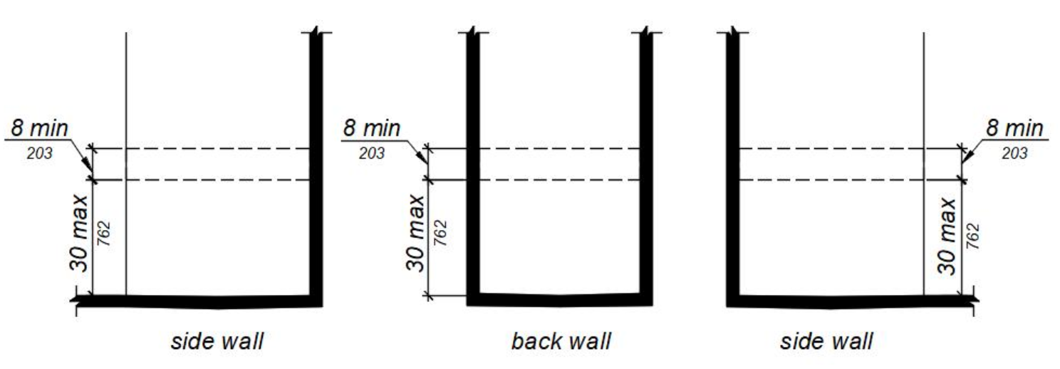
FIGURE 11B-809.10.6.4 REINFORCEMENT FOR GRAB BARS.
11B-809.10.6.5 Thresholds.
Where provided thresholds shall be 2 inches (51 mm) maximum in height and have a beveled or sloped angle not exceeding 1 unit vertical in 2 units horizontal (26.6 degrees from the horizontal). Thresholds 1/2 inch (12.7 mm) or less in height shall have a beveled or sloped angle not exceeding 1 unit vertical in 1 unit horizontal (45 degrees from the horizontal).
11B-809.10.6.6 Controls.
Controls and operating mechanisms shall comply with Section 11B-309.4.
11B-809.10.6.7 Shower enclosures.
Doors and panels of shower enclosures shall comply with Section 11B-809.10.5.4.
11B-809.10.7 Water closets.
Water closets required by Section 11B-809.10 shall comply with this section.
11B-809.10.7.1 Floor space.
The floor space at water closets shall be 48 inches (1219 mm) wide minimum measured perpendicular to the side wall. A floor space 48 inches (1219 mm) wide minimum by 36 inches (914 mm) deep minimum shall be provided in front of the water closet.
Exception: The 48-inch (1219 mm) minimum clear width may be reduced to 36 inches (914 mm) minimum for lavatories, cabinets, wing walls, or privacy walls located immediately adjacent to a water closet which extend 24 inches (610 mm) maximum in depth.
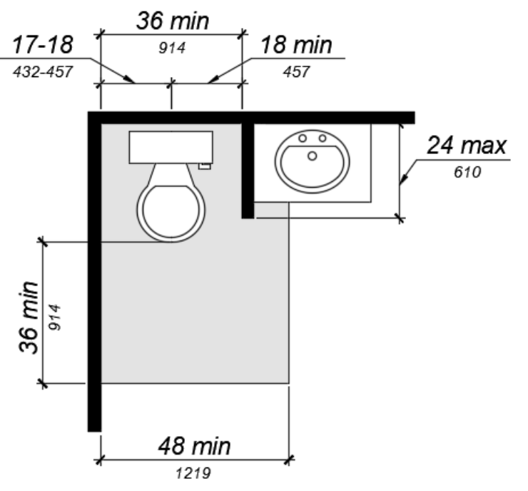
FIGURE 11B-809.10.7.1 FLOOR SPACE.
11B-809.10.7.2 Location.
Water closets shall be located within bathrooms in a manner that permits a grab bar to be installed on at least one side of the fixture. The centerline of the water closet shall be 17 inches (432 mm) minimum to 18 inches (457 mm) maximum from a wall or partition that is 54 inches (1372 mm) minimum in length. In locations where water closets are adjacent to other walls, vanities, lavatories or bathtubs, the centerline of the fixture shall be 18 inches (457 mm) minimum from the obstacle.
11B-809.10.7.3 Reinforcement for grab bars.
Reinforcement for grabs bars shall comply with the following:
-
Where water closets are not placed adjacent to a side wall capable of accommodating a grab bar, the bathroom shall have provisions for installation of floor-mounted, foldaway or similar alternative grab bars.
-
Where water closets are placed adjacent to a side wall, reinforcement shall be installed on both sides or one side and the back. Where reinforcement is installed at the back, it shall be installed between 30 inches (762 mm) maximum and 38 inches (965 mm) minimum above the finish floor. The grab bar reinforcement shall be 8 inches (203 mm) minimum in height. The backing shall 40 (sic) inches (1016 mm) minimum in length.
-
Where the water closet is located adjacent to lavatories, cabinets, wing walls, or privacy walls the grab bar reinforcement shall be 36 inches (914 mm) in length. Reinforcement installed at the side wall of the water closet shall be between 30 inches (762 mm) minimum to 38 inches (965 mm) maximum above the finish floor. The reinforcement shall be 10 inches (254 mm) maximum from the rear wall and shall extend 30 inches (762 mm) minimum in front of the water closet. The grab bar reinforcement shall be 8 inches (203 mm) minimum in height.
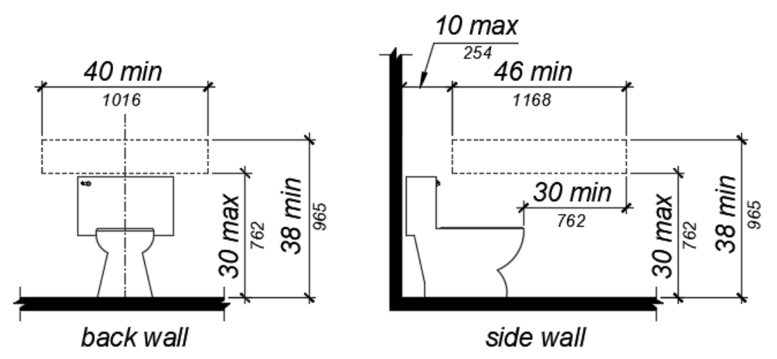
FIGURE 11B-809.10.7.3 REINFORCEMENT FOR GRAB BARS.
11B-809.10.7.4 Seat height.
Water closet seats shall be 15 inches (381 mm) minimum and 19 inches (483 mm) maximum measured to the top of the seat above the finish floor.
11B-809.10.7.5 Controls.
Controls shall be mounted 44 inches (1118 mm) maximum above the finish floor. The force required to activate controls shall be 5 pounds (22.2 mm) maximum.
11B-809.10.8 Lavatories, vanities, mirrors and towel bars.
Bathing rooms or powder rooms required to comply with Section 11B-809.10 shall provide lavatories complying with this section. Where mirrors or towel bars are provided, no less than one of each shall comply with this section.
11B-809.10.8.1 Location.
Lavatories without base cabinets shall be installed with the centerline 18 inches (457 mm) minimum from an adjoining wall or fixture to allow for forward approach. Lavatories with base cabinets shall be installed with the centerline 24 inches (610 mm) minimum from an adjoining wall or fixture to allow for a parallel approach. The top of the lavatory rim shall be 34 inches (864 mm) maximum above the finished floor.
11B-809.10.8.2 Floor space.
A floor space 30 inches (762 mm) minimum by 48 inches (1219 mm) minimum shall be provided centered on the lavatory.
11B-809.10.8.3 Cabinets.
Cabinets shall be removable without the use of specialized knowledge and/or tools. The finished floor shall extend to the wall under the lavatory.
11B-809.10.8.4 Knee and toe clearance.
Knee and toe clearance shall be provided and comply with Section 11B-306.
11B-809.10.8.5 Plumbing protection.
Plumbing protection shall comply with Section 11B-809.9.7.
11B-809.10.8.6 Controls.
Faucet controls and operating mechanisms shall comply with Section 11B-309.4.
11B-809.10.8.7 Mirrors and towel bars.
Where mirrors are provided the bottom edge of the reflective surface shall be 40 inches (1016 mm) maximum above the finish floor. Where towel bars are provided they shall be installed 40 inches (1016 mm) maximum above the finish floor to the top of the bar.
11B-809.11 Washing machines and clothes dryers.
Where washing machines and clothes dryers are provided in residential dwelling units with adaptable features, one of each type shall be provided.
11B-809.12 Electrical receptacles, controls and switches.
Electrical receptacles on branch circuits of 30 amperes or less, communication system receptacles, controls and switches shall be located as follows:
-
Where there is no obstruction, 48 inches (1219 mm) maximum measured from the top of the receptacle box and 15 inches (381 mm) minimum measured from the bottom of the receptacle box to the finish floor.
-
Where the reach is over an obstruction, electrical receptacles, controls and switches shall comply with Sections 11B-309.2 and 11B-308.3.
-
When the reach is over a kitchen work surface and base cabinet, the work surface shall be 36 inches (914 mm) maximum above the finish floor and 25 1/2 inches (650 mm) maximum in depth. The base cabinet shall be 24 inches (610 mm) maximum in depth.
-
Where receptacles are provided in a kitchen at a corner work surface, one receptacle shall be located 36 inches (915 mm) from either wall at the inside corner.
Exceptions:
a. Electrical receptacles installed as part of permanently installed baseboard heaters.
b. Electrical receptacles in floors adjacent to sliding panels or walls.
c. Baseboard electrical receptacles in relocatable partitions, window walls or other electrical convenience floor outlets.
d. Appliances (e.g., stoves, dishwashers, range hoods, microwave ovens and similar appliances) which have controls located on the appliance.
e. Electrical receptacles dedicated to specific appliances.
f. Circuit breakers.
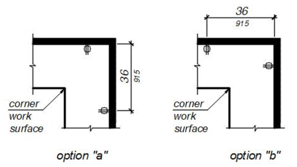
FIGURE 11B-809.12
ELECTRICAL RECEPTACLES AT CORNER WORKSURFACES
User Comments/Questions
Add Comment/Question