2019 California Standards for Accessible Design Guide (effective January 1, 2020 with July 1, 2021 amendments)
11B-1009.5 Transfer systems.
Transfer systems shall comply with Section 11B-1009.5.
11B-1009.5.1 Transfer platform.
A transfer platform shall be provided at the head of each transfer system. Transfer platforms shall provide 19 inches (483 mm) minimum clear depth and 24 inches (610 mm) minimum clear width.
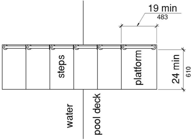
FIGURE 11B-1009.5.1 SIZE OF TRANSFER PLATFORM
11B-1009.5.2 Transfer space.
A transfer space of 60 inches (1524 mm) minimum by 60 inches (1524 mm) minimum with a slope not steeper than 1:48 shall be provided at the base of the transfer platform surface and shall be centered along a 24 inch (610 mm) minimum side of the transfer platform. The side of the transfer platform serving the transfer space shall be unobstructed.
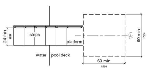
FIGURE 11B-1009.5.2 CLEAR DECK SPACE AT TRANSFER PLATFORM
11B-1009.5.3 Height.
The height of the transfer platform shall comply with Section 11B-1009.4.2.
11B-1009.5.4 Transfer steps.
Transfer step height shall be 8 inches (203 mm) maximum. The surface of the bottom tread shall extend to a water depth of 18 inches (457 mm) minimum below the stationary water level.

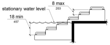
FIGURE 11B-1009.5.4 TRANSFER STEPS
11B-1009.5.5 Surface.
The surface of the transfer system shall not be sharp and shall have rounded edges.
11B-1009.5.6 Size.
Each transfer step shall have a tread clear depth of 14 inches (356 mm) minimum and 17 inches (432 mm) maximum and shall have a tread clear width of 24 inches (610 mm) minimum.
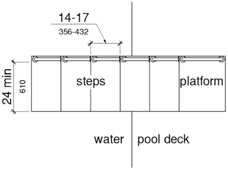
FIGURE 11B-1009.5.6 SIZE OF TRANSFER STEPS
11B-1009.5.7 Grab bars.
At least one grab bar on each transfer step and the transfer platform or a continuous grab bar serving each transfer step and the transfer platform shall be provided. Where a grab bar is provided on each step, the tops of gripping surfaces shall be 4 inches (102 mm) minimum and 6 inches (152 mm) maximum above each step and transfer platform. Where a continuous grab bar is provided, the top of the gripping surface shall be 4 inches (102 mm) minimum and 6 inches (152 mm) maximum above the step nosing and transfer platform. Grab bars shall comply with Section 11B-609 and be located on at least one side of the transfer system. The grab bar located at the transfer platform shall not obstruct transfer.
Exception: Grab bars on transfer systems shall not be required to comply with Section 11B-609.4.
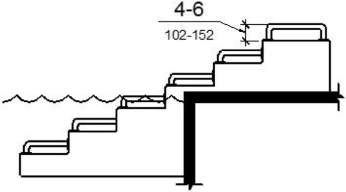
(a) individual grab bars
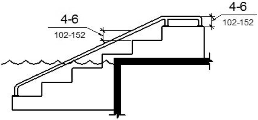
(b) continuous grab bars
FIGURE 11B-1009.5.7 GRAB BARS
User Comments/Questions
Add Comment/Question