Overview of FSTAG Implementation Process
Now that you have learned about the extent of application, general exceptions, and the technical requirements, you may wonder how the whole process ties together. Use the following four easy steps and the handy process flowchart in the appendix to implement FSTAG on your trail design projects. Following this process will help you verify that the trail design complies with the technical requirements to the extent practicable, help you document how and where the technical requirements can, or cannot, be applied, and confirm that the character, trail class, and experience of the setting will not be changed. It also can be used as a field guide when locating or rerouting a trail.
Step 1: Determine the Applicability of FSTAG
After a decision has been made to design or alter a trail, three questions must be asked:
1. Does the work meet the definitions for new construction or alteration? Definitions are in "Understanding Trail Terminology" of this guidebook.
-
If yes,
2. Is the Designed Use "Hiker/Pedestrian"?
-
If yes,
3. Does the proposed trail connect to a trailhead or to a trail that substantially complies with FSTAG? (Trailhead is defined in "Understanding Trail Terminology.")
If the answer to any of these questions is no, FSTAG does not apply and no further analysis is required. The finding and reasons that FSTAG does not apply should be briefly documented and put in the project file. Figure 140 shows step 1. Even if compliance with FSTAG is not required, you should try to incorporate accessibility where opportunities exist and to the extent you can without changing the character of the setting and, therefore, the hiking experience.
If the answer to all three questions is yes, the designer moves to step 2.
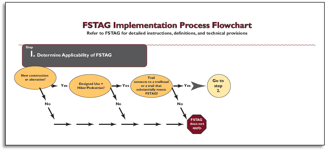
Figure 140—Step 1 of the Forest Service Trail Accessibility Guidelines implementation process. (For a larger image please click here.)
Design Tip
Evaluate your trail design for Forest Service Trail Accessibility Guidelines (FSTAG) compliance using on-the-ground layout.
In order to work through steps 2, 3, and 4 of the implementation process, lay out a proposed trail alignment on the ground and conduct the evaluation as you walk the flag line. Base the review and analysis required in these steps on actual field conditions, rather than relying only on topographic maps.
Step 2: Identify the Presence of Limiting Factors
This step addresses the condition criteria accepted by the U.S. Access Board for identifying when extreme environmental barriers allow the use of General Exception 2. These barriers are defined in the first four limiting factors in FSTAG, section 7.2.2.1 "Determining Impracticability" and are explained in "General Exceptions in FSTAG" of this guidebook. The sequence for identifying the limiting factors may vary and does not need to be done in the order illustrated in the process flowchart.
Work your way through the process flowchart by asking four questions, each related to one of the limiting factors. The first question will be explained in detail to serve as an example for the other three.
Does the combined trail running slope (grade) and cross slope exceed 1:2.5 (40 percent) for a continuous distance of 20 feet (6 meters) or more?
Construction Tip
Choose a method to measure the running slope.
There are a number of ways you can measure running slope. You can perform an informal survey between obvious trail slope breaks with a hand level, survey rod, and measuring chain (figure 141). You can use a digital level (figure 142). You can also perform a more detailed trail assessment such as the universal trail assessment process developed by Beneficial Designs (http://www.beneficialdesigns.com/).
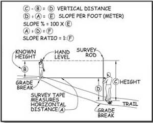
Figure 141—Surveying trail grade with a hand level.
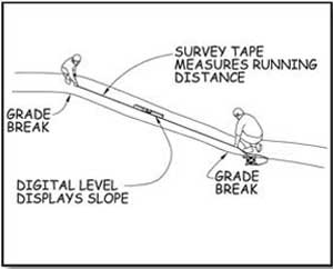
Figure 142—Surveying trail grade with a digital level.
If not, FSTAG may still apply, so you should consider Design Tip the next limiting factor. A continuous distance means a sustained running slope (grade) without rest areas or more moderate slopes. If the alignment can be relocated to get a more moderate slope, this limiting factor doesn't apply.
If the combined slope exceeds 1:2.5 (40 percent) for a continuous distance of 20 feet (6 meters) or more, document the length of trail that exceeds the technical requirements for slopes, the location of the area, and your data source (field survey, clinometer, and so forth). Keep this information for use in step 4.
Next, determine whether a condition for an exception exists that permits a deviation from the technical requirements for slope. If there is no condition for an exception, FSTAG may still apply, so you should proceed to the next limiting factor.
If a condition for an exception does exist, document the length of trail affected by the condition for an exception, what exception applies, and the location of the area.
Next, consider whether the combined trail running slope (grade) and cross slope is so excessive that it is impracticable for the entire trail to comply with the technical requirements. If so, FSTAG does not apply to this trail at all and no further review or analysis is required. Document the reason for the determination, retain it in the project file, and notify the U.S. Access Board, as explained in "Documenting Exceptions and Notifying the U.S. Access Board About Exemptions" of this guidebook.
Finally, consider the end section of trail between the limiting factor and the trailhead or another trail that substantially complies with FSTAG. Is there a prominent feature between the end of the trail and the limiting factor? If so, consider constructing the section of trail between the end of the trail and the prominent feature in compliance with the technical accessibility requirements. Doing so is not required, but it is often good management and good customer service.
Design Tip
Use a rule of thumb to estimate firmness and stability.
What sort of surface is firm and stable? If the answer to both of the following questions is yes, the surface is probably firm and stable.
-
Could a person ride a narrow-tired bicycle across the surface easily without making imprints? (Bicycle tires are similar to the large rear wheels of a wheelchair.)
-
Could a folding stroller with small, narrow plastic wheels containing a 3-year-old be pushed easily across the surface without making imprints? (The stroller's wheels are similar to the front wheels of a wheelchair.)
While this method for determining firmness and stability isn't scientifically accurate, it has proven to be effective.
Work your way through the other three limiting factors the same way. The design tips may help you.
Is the surface neither firm nor stable for 45 feet (14 meters) or more?
Is the trail tread width 12 inches (227 millimeters) or less for a distance of at least 20 feet (6 meters)?
Is there an obstacle at least 30 inches (760 millimeters) high extending across the full width of the trail?
Design Tip
Determine when trail width is a limiting factor.
Measuring the existing trail width is easy—just use a measuring tape to get the side-to-side distance of the narrowest stretch of trail. Figuring out whether that width can be changed may be a little more difficult. The trail may be less than 12 inches (227 millimeters) wide, but if you can widen it in its current location or move the trail alignment to an area where it can be wider, the limiting factor doesn't apply.
If you find a limiting factor where a condition for an exception applies, there's no reason to evaluate the trail beyond that point for successive limiting factors unless the rest of the trail connects to a trailhead or a trail that substantially complies with FSTAG. Just look at the section of trail between the limiting factor or prominent feature and the trailhead or connecting trail. Figure 143 shows step 2.
If there are no limiting factors that would prevent compliance with FSTAG, proceed to step 3.
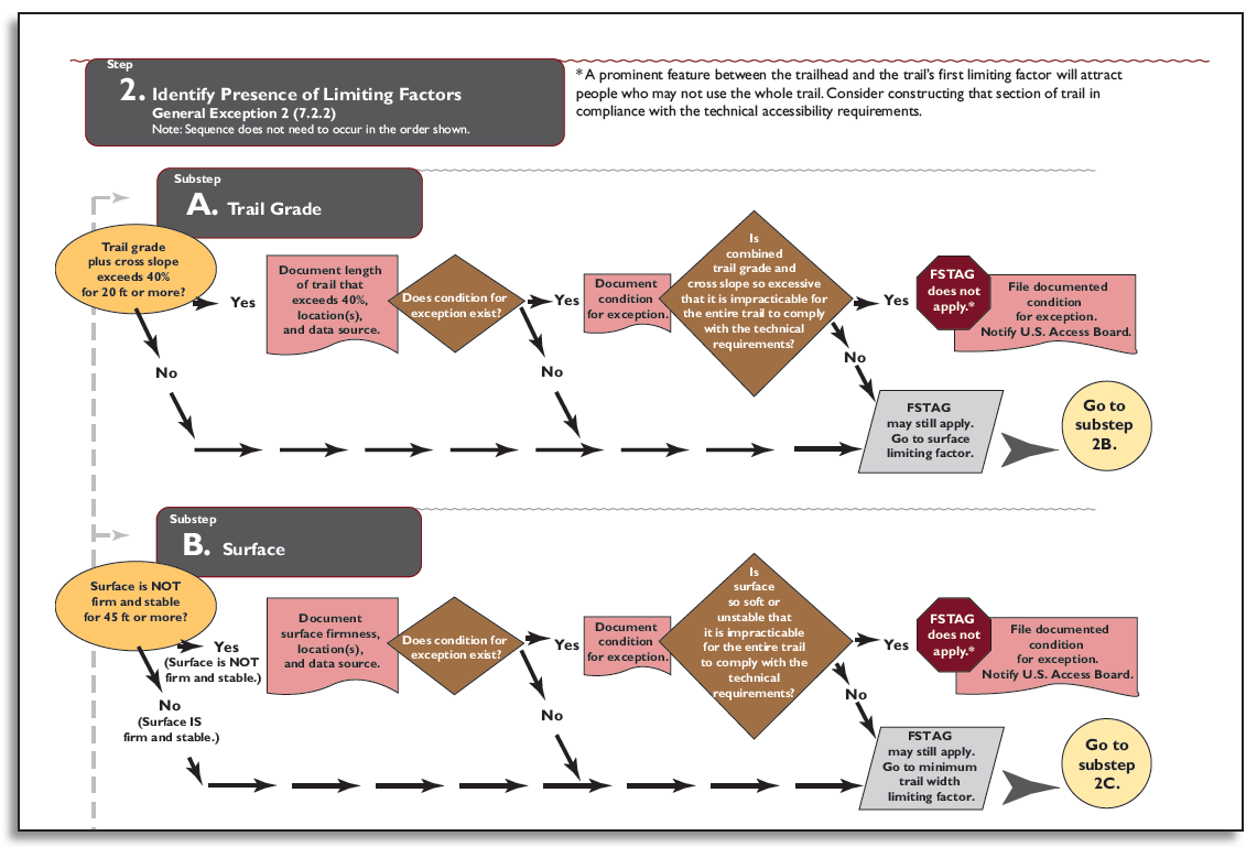
Figure 143—Step 2 of the Forest Service Trail Accessibility Guidelines implementation process. (For a larger image please click here.)
Step 3: Apply the Accessibility Provisions
This step involves looking at FSTAG, sections 7.4.1 through 7.4.8, which contain the technical requirements for trail grade, cross slope, resting interval, surface, clear tread width, passing space, tread obstacles, protruding objects, and openings.
This summary and the process flowchart don't contain everything you need to know about trail design requirements. Refer to FSTAG for detailed instructions, definitions, conditions for an exception, accessibility provisions, and allowable deviations.
A series of questions with yes or no answers is asked for each of the technical requirements, similar to step 2. Use the trail running slope (grade) as an example.
First, look at the existing conditions on the ground and determine whether the trail alignment complies with the required running slopes of a maximum of 1:20 (5 percent) for any distance, 1:12 (8.33 percent) for up to 200 feet (61 meters), 1:10 (10 percent) for up to 30 feet (9 meters), and so forth. Could a change in trail alignment facilitate meeting the requirement? If not, does one of the conditions for an exception prevent compliance? If the trail alignment complies with the required slope or there is no condition for an exception, compliance with the technical requirement for trail grade is required. If the grade requirement can't be met because of a condition for an exception, measure and record the length of trail that will deviate from the technical requirement. Then consider how the running slope could be adjusted to get as close as practicable to the requirement. Record what the slope will be on that section of the trail and proceed to the next technical requirement.
Each technical requirement is addressed in a similar manner. Make a determination for every technical requirement: either compliance is required or deviations are permitted. Be sure to measure and record the length of the trail on which each deviation from a particular technical requirement will occur. Figure 144 shows step 3. After you work through all the technical requirements, proceed to the last step.
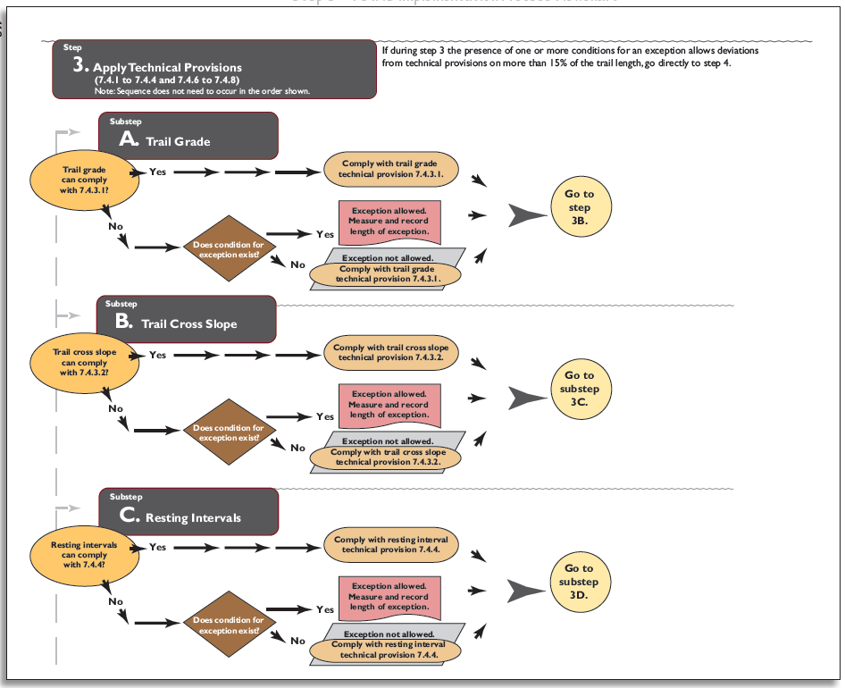
Figure 144—Step 3 of the Forest Service Trail Accessibility Guidelines implementation process. (For a larger image please click here.)
If at any point during step 3 you find that the recorded length of the trail that contains deviations adds up to 15 percent or more of the total trail length, proceed directly to step 4.
Step 4: Calculate Cumulative Deviation Percentage
This final step addresses the suggested objective criteria for identifying when extreme or numerous environmental barriers allow the use of General Exception 2. These barriers are defined in the five limiting factors in FSTAG, section 7.2.2.1.
Design Tip
Apply the process.
Figure 145 helps illustrate how to apply the process by calculating cumulative deviations and considering a prominent feature. The drawing shows that:
-
Deviations occur on more than 15 percent of the trail because 15 percent of 950 feet equals 142.5 feet (15 percent of 290 meters equals 43.5 meters), but the deviations total 216 feet (66 meters).
-
The trail does not have to comply with the guidelines.
-
The first point of deviation occurs 400 feet (122 meters) from the trailhead and the vista is only 250 feet (76 meters) from the trailhead. It may be appropriate to construct the trail in compliance with the guidelines from the trailhead to the vista.
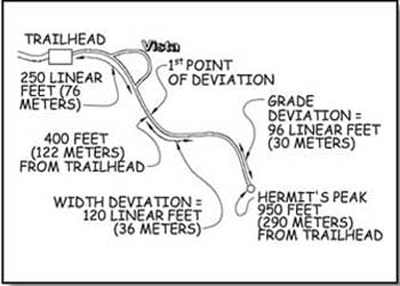
Figure 145—This trail schematic illustrates how to determine where the trail must comply with Forest Service Trail Accessibility Guidelines.
Add the measurements of permitted deviations from step 3. If these deviations occur on 15 percent or more of the total trail length, FSTAG doesn't apply to the trail. Figure 146 shows step 4.
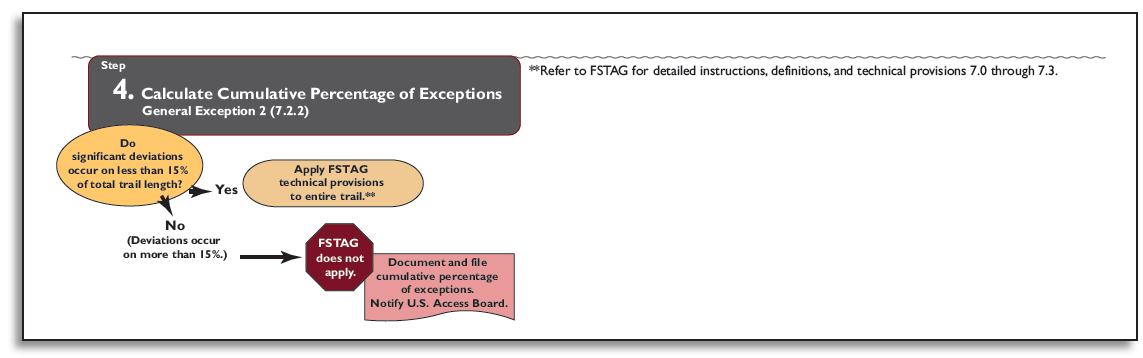
Figure 146—Step 4 of the Forest Service Trail Accessibility Guidelines implementation process. (For a larger image please click here.)
User Comments/Questions
Add Comment/Question