Independent Wheelchair Transfers in the Built Environment: How Transfer Setup Impacts Performance Phase 2: Final Report
Methodology
This study was approved by the University of Pittsburgh's Institutional Review Board and all participants provided informed consent before participating in any test procedures.
Participants
The target sample populations were individuals who live in the community and use a wheeled mobility device, as well as having the ability to transfer independently and represent a broad spectrum of disabilities. Participants were eligible to participate if they (1) were at least 7 years old, (2) self-reported ability to perform independent transfers to/from a WMD with or without a transfer aide, (3) owned a WMD, (4) have been using the WMD for at least one year. Participants were excluded if they had (1) significant upper extremity pain or injury that would inhibit their ability to transfer, (2) any active pressure sores, (3) any history of pressure sores that would be exacerbated with transfer activity and (4) cognitive impairments that would impair following simple instructions.
Participants were tested at the 28th National Disabled Veterans Winter Sports Clinic in Snowmass Village, Colorado during March 2014; at the Hiram G Andrews Center in Johnstown, Pennsylvania during September 2013 and at the Human Engineering Research Laboratories in Pittsburgh, Pennsylvania between July 2013 and July 2014.
Design Criteria for the Transfer Station
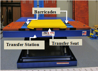
A custom-built modular transfer station was designed and fabricated to meet the study goals. The station was designed to investigate the impact handhelds, back rests, heights, and seat widths have on transfer performance. The design criteria for the station listed in Table 1 were derived from multiple design requirements in the standards where both adults and children are expected to transfer.
Table 1. Transfer Station Design Criteria
| Design Element |
Dimensions |
|
Seat width ranges for platform 1 and 2 |
Adjustable between 18” and 30” |
|
Seat depth for platform 1 and 2 |
Fixed at 16” |
|
Vertical height distance between platform 1 and platform 2 |
Adjustable between 0”-8” |
|
Platform 1 vertical height range |
Adjustable between 10" and 43” |
|
Horizontal distance (gap) between platform 1 and platform 2 |
0” for the adjacent two-step transfer |
|
Clear area in front of station for positioning the WMD |
90" x 72" |
|
Optional ramp between platform 1 and 2 |
Fixed 30" wide |
|
Optional grab bars |
Fixed 1-1/2" diameter round: |
|
Optional back rest on platform 1 |
Fixed 16" wide |
Seat Heights: Transfer platforms in play areas need to be between 11 and 18 inches maximum above the ground (ADA-ABA Section 1008.3.1.2)[7]. Additionally, transfer walls at pool decks are between 16 and 19 inches above the ground (ADA-ABA Section 1009.4.2) [7]. The maximum height allowed between two transfer steps is 8 inches in play areas (ADA-ABA Section 1008.3.2) [7] and swimming pools, wading pools, and spas (Section 1009.5.4). No minimum height for steps is specified. Based on earlier findings (Phase 1 Final Report), there was concern that the 8 inch maximum may not accommodate some wheelchair users. Because of these concerns the station was designed to allow for adjustments in height up to, but not to exceed the 8 inch maximum height allowance.
7. US Access Board. ADA-ABA Accessibility Guidelines for Buildings and Facilities (ADA-ABA). 2002. http://www.access-board.gov/guidelines-and-standards/buildings-and-sites/about-the-ada-standards/background/ADA-ABA
Seat width and depth: ADA-ABA currently requires a minimum entry point of 24 inches for transfer steps in play (Section 1008.3.1.1) [7] and pool areas (Section 1009.4.5) [7]. Additionally a 30 inch minimum width has been proposed medical diagnostic exam tables. We selected 18 inches minimum seat width as a starting point with the potential to grow to 30 inches. The seat depth was not a primary variable of interest and was fixed at 16 inches. This dimension is within the range of seat depths allowed for transfer steps in play and pool areas and for proposed diagnostic equipment (14 to 17 inches). Transfer surfaces on the station were padded with 1" foam and a vinyl cover for comfort and to protect the skin during the experimental protocol.
7. US Access Board. ADA-ABA Accessibility Guidelines for Buildings and Facilities (ADA-ABA). 2002. http://www.access-board.gov/guidelines-and-standards/buildings-and-sites/about-the-ada-standards/background/ADA-ABA
Ramp: A ramped surface was designed to insert between two steps and serve as an integrated sliding board to assist with the transfers by bridging the gap between steps. Ramped surfaces used for transferring are not currently part of the standards but are present in some real world transfer situations. For example, some amusement park rides have sloped surfaces built into the structure of the ride vehicle to help individuals transfer into and out of the vehicle. A ramped surface was made to attach between the two transfer platforms ('steps') and span across an 8 inch wide space. The angle of the ramp varies as the second platform height changes and the ramp grows or shrinks in size so as to maintain a constant 8-inch gap between the two transfer steps. The ramp had a constant width of 30 inches and was 1 inch thick. The minimum length was 8 inches and the maximum length was 11 inches.
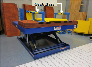
Grab bars: Section 609 of the ADA-ABA standards [7] includes provisions for grab bars in areas where transfers are expected. Grab bars can have either circular or non-circular cross-sections [7]. Circular grab bars are more commonly used and were selected for testing. The outside diameter dimension range for circular cross-section grab bars are between 1.25 and 2 inches. A 1.5 inch diameter was chosen for the study. Section 1009.4.5 of ADA-ABA [7] describes grab bars to be used on swimming pool, wading pool, and spa transfer walls. This standard gives the grab bar height range of 4 to 6 inches from the wall to the top of the gripping surface. Two grab bar height options were designed for the study; a 6-inch and a 2.75-inch. The 2.75-inch was added to examine the effects of a handheld when located closer to the transfer surface. A 4 inch grab bar was not made because it was felt that the differences between the 6 inch and 4 inch would be negligible. The grab bars were designed to be 16 inches long so that they could span the depth of the platforms. Section 1009.4.5 of the ADA standards also gives the dimensions for grab bars spacing [7]. When two grab bars are provided there should be at least a 24-inch clearance between them. Since transfer seat width was a modifiable variable in the study, the grab bars were designed to have a range between 18 and 30 inches. This allows for another 6 inches below and above the standard to be evaluated (note: provisions for grab bars were applied to the handhelds which are referred to in several places throughout this report).
7. US Access Board. ADA-ABA Accessibility Guidelines for Buildings and Facilities (ADA-ABA). 2002. http://www.access-board.gov/guidelines-and-standards/buildings-and-sites/about-the-ada-standards/background/ADA-ABA
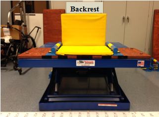
Backrests: The backrest design for platform 1, the first surface that participants transferred to from their WMD as seen in Table 2, was based on bench seat back supports in section 903.5 of the ADA [7]. Back supports should be a minimum of 18 inches from the seat surface to the top of the support. Three different height back supports were designed for this study; a 14-inch, a 17-inch, and a 20-inch. These heights were chosen because they range from below and above the current minimum requirement. They were designed to be easily added and taken off of the station by sliding them in and out of two circular slots located in the scissor lift table top. Each backrest was also designed to have a 5o angle for comfort.
7. US Access Board. ADA-ABA Accessibility Guidelines for Buildings and Facilities (ADA-ABA). 2002. http://www.access-board.gov/guidelines-and-standards/buildings-and-sites/about-the-ada-standards/background/ADA-ABA
Clear space: A grid 72 inches long by 90 inches wide was used to facilitate the recording of space requirements for each WMD user (Figure 1). This is more space than what is required in the standards. If a person required space beyond the size of the grid, the additional distance was measured and recorded. The grid was positioned such that it was centered with the middle of the transfer station. A coordinate system was assigned to the grid so that each cell was given an alphabetic (y-direction) and numeric (x-direction) name. The center point (0,0) was located on the line in-between the grid values A15 and A16. There were a total of 720, 3 X 3 inch cells in the grid. To calculate the space, three points were recorded for transfers to and from the platform: a point to the right of center, a point to the left of center, and a depth value (Figure 2). These points were found by recording each WMD's outermost points on the grid. When calculating both right of center and left of center values any point right of the reference line (A15/A16) was assigned a positive (+) value, while any point left of the reference line was assigned a negative (-) value. For the depth, all values were positive (+). Space data was recorded as the maximum distance away from the A15/A16 reference line to the right (right of center), the maximum distance away from the A15/A16 reference line to the left (left of center), and the maximum distance away from the front edge of the platform (depth). The angle the WMD was positioned with respect to the transfer station was measured from the front edge of the platform as shown in Figure 2. An angle of 0 degrees was given if the WMD was positioned parallel to the x-direction of the coordinate system (e.g. in parallel with the front edge of the platform). An angle of 90 degrees was given if the WMD was positioned parallel to the y-direction of the coordinate system (e.g. perpendicular to the front edge of the platform).
![Picture of the grid used to measure the location and orientation of set up that was used by study participants when transferring. The grid is made up of three in by three inch squares and is 72 by 90 inches in dimension. The squares are labeled with letters starting with A1 in the top left corner. The numbers increase moving down the column and the letters move from A to X moving across the row, with the zero zero [sic] point marked on the grid between A15 and A16. The grid is divided in half between rows 15 and 16. The coordinate system used to calculate the locations is described. Locations above the midline are marked with a positive x and locations below the midline are negative x. The horizontal axis is marked with a y. The transfer station is next to the grid stationed exactly 24inches from the top and bottom. The station is 42 by 50 inches.](/images/17751)
Figure 1. Scaled version of the 72 inch x 90 inch grid used to record position measurements
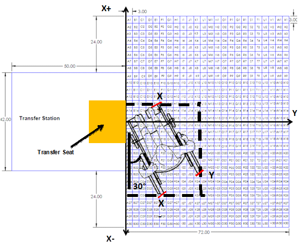
Figure 2. Location of wheelchair and measurement points for clear space calculations. Also shown is the location of the transfer seat on the transfer station. The transfer seat had a fixed depth of 16 inches. The width of the seat was adjustable and could range from a minimum of 18 inches to a maximum of 30 inches. The minimum dimensions of the seat are depicted above.
Initial Measures and Transfer Setup
Wheelchair measurements were completed without the person seated in their wheelchair. The device seat to floor height was measured as the linear distance between the front of the seat, center-line point on top of the cushion (if present) and the floor (Figure 3 left). This location was chosen to account for any hammocking, wear or compression of the seat upholstery and/or cushion. However, for the setup of the baseline level transfer (when the person and mobility device were in a position next to platform ready to transfer), if there was a noticeable difference (one inch or more) between the occupied seat-to-floor height at the same center-line point at the front of the seat (plus cushion if present) (Figure 3 right) and the height of the platform which was initially set based on the unoccupied seat to floor height, we adjusted the platform to match the occupied seat-to-floor height and this new measurement replaced the unoccupied measurement in the data set. This methodology is based on ANSI/RESNA standards used to measure the wheelchair seat to floor height when conducting standards testing. This approach is also widely promoted in rehabilitation research (A Clinical Application Guide to Standardized Wheelchair Seating Measurements of the Body and Seating Support Surfaces, See References for full guidelines)[9].
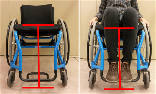
Figure 3: Seat height measurements in an unoccupied (20.5" seat to floor height) and occupied wheelchair (19.5" seat to floor height).
9. A Clinical Application Guide to Standardized Wheelchair Seating Measurements of the Body and Seating Support Surfaces. (2013) Revised Edition, University of Colorado/Assistive Technology Partners Denver, Colorado, USA, Available from: https://www.assistivetechnologypartners.org
Transfer Protocols
For each transfer, participants were asked to position themselves next to the platform as they normally would to prepare for a transfer. The angle of their WMD relative to the front of the platform and the x and y positions of the WMD using the grid as described above were recorded (see Figure 3). The first platform was adjusted to be level with the participant’s WMD seat height. The barricades shown in Table 2 (top picture) were adjusted to the participant’s preferred seat width. The participant transferred from their own WMD to the first platform and back to his or her device. The participant's seat width was recorded. The next five protocols (A-E) were performed in random order (Table 2). After each transfer in each protocol, any changes made to device positioning (if any), use of a transfer board, and surface(s) used for the leading hand (e.g. reaching to new surface) and trailing hand (e.g. left behind during move to new location) were recorded. For each transfer for protocols A-C, a measurement of how high and how low a participant transferred was recorded. This measurement was made from the ground to the top of the yellow seat cushion that is on the station (Table 2) when the participant was not seated on the station after they had returned to their mobility device seat; this value was recorded in inches for all transfers.
Table 2. Summary description and experimental setup for the five protocols (A-E)
|
Protocol A: Adjustable Height
|
 |
|
Protocol B: Adjustable Height/Grab Bars
|
 |
|
Protocol C: Adjustable Height Backrest and Grab Bar Options
|
 |
|
Protocol D: Adjacent Two-Step
|
 |
|
Protocol E: Two-Step with Ramp
|
 |
Protocol A: Adjustable Height
This protocol consisted of two parts: maximum height transfer and a lowest height transfer. From the Initial Setup, the scissor lift was adjusted incrementally in height so that platform 1 could be made higher or lower than the participant’s seat. The amount of vertical distance that the seat was raised/lowered each time depended on the participant's perceived and observed transfer abilities. The participant was asked to perform a transfer at each height increment until the platform was raised/lowered to a level that they no longer felt they could perform a transfer based on their own judgment or that of the study personnel. The maximum and minimum transfer heights that were attainable were recorded.
Protocol B: Adjustable Height Protocol: Grab Bar Option
This protocol consisted of three parts: level height transfer, maximum height transfer, and a lowest height transfer. The barricades from Protocol A were replaced with grab bars of two varying heights (2.75 inches and 6 inches) depending on the participant’s preference. They were also adjusted to the participant’s preferred seat width if different from the initial setup. The rest of the protocol followed the same procedure as Protocol A where the participant transferred to the first platform and back.
Protocol C: Adjustable Height: Grab Bar and Backrest Option
This protocol consisted of three parts: level height transfer, maximum height transfer, and a lowest height transfer. Protocol C used the same grab bar set up as Protocol B, but added a backrest attached behind platform 1. The participant chose one of three different height backrests (16” X 14”, 16” X 17”, and 16” X 20”). The rest of the protocol followed the same as Protocol B.
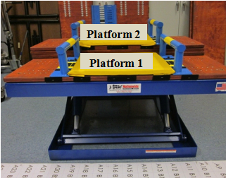
Protocol D: Adjacent Two Step Transfer
This protocol consisted of two parts: level to a higher seat and level to lower seat. From Protocol B the scissor lift was adjusted so that the first platform was set level with the participants WMD. A second platform was added to the scissor lift behind platform 1 so that they were at a 90o angle to each other. The vertical distance between platform 1 and 2 was adjusted incrementally in height: higher and lower by adding one-inch boards to either platform. The participant was asked to perform transfers to the first platform, to the second platform, back to the first platform, and then finally back to his/her WMD. The vertical distance that the second platform was raised/lowered each time depended on the participant's perceived and observed transfer abilities. The participant was asked to repeat the transfers until the second platform was raised/lowered to a level that they no longer felt they could perform a transfer based on their own judgment or that of the study personnel. The maximum and minimum vertical distances that were attainable were recorded.
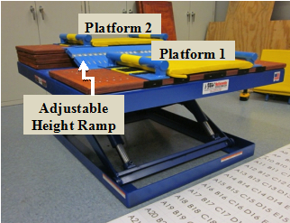
Protocol E: Two Step Transfer with Ramp
This protocol consisted of two parts: level to a higher seat and level to lower seat. As with Protocol D, the first platform was set level with the participants WMD. An adjustable height ramp was attached between platform 1 and platform 2. The ramp was used to get up to and down from platform 2. The vertical distance between platform 1 and 2 was adjusted incrementally in height: higher and lower by adding one-inch boards to either platform. The ramp was capable of growing in length as the vertical distance between platforms grew. The participant was asked to perform transfers to platform 1, to platform 2 (via the ramp), back to platform 1, and then finally back to his/her WMD. The vertical distance that the second seat was raised/lowered each time depended on the participant's perceived and observed transfer abilities. The participant was asked to repeat the transfers until platform 2 was raised/lowered to a level that they no longer felt they could perform a transfer based on their own judgment or that of the study personnel. The maximum and minimum vertical distances that were attainable were recorded.
Data Analysis
Descriptive statistics were used to find the population-based percentile level, highest, and lowest heights for transfers for the one-step transfer protocols A, B, and C and the two-step transfer protocols D and E. The 5th, 25th, 50th, 75th, and 95th percentiles were recorded along with the minimum and maximum heights attained for each part of each protocol. A repeated measures analysis of variance (ANOVA) statistical test was used to evaluate the effects of adding grab bars and a backrest to the station with regards to the maximum and minimum heights achieved with a significance level set at α<0.05.
For protocols A, B and C percentages were calculated for the space needed to transfer to and from the transfer station. Areas centered around the transfer station were defined and the percentage of the study participants who were able to transfer in that area were calculated. Percentages were calculated instead of percentiles due to the complexity of the measurements. For example, the area measurement depends on two variables that cannot be analyzed separately: the amount of space occupied by the physical dimensions of the WMD user and the actual location of the WMD and user relative to the center of the first platform. Graphical techniques were developed to illustrate the areas and locations that WMD users used to position themselves relative to the station.
User Comments/Questions
Add Comment/Question