Recommendations on Standards for the Design of Medical Diagnostic Equipment for Adults with Disabilities, Advisory Committee Final Report
Sub-Committee Summary of Scope for Recommendations
The Full Committee and Sub-Committee are both in agreement that Beds are excluded from these proposed standards as beds are used for therapeutic and not diagnostic procedures. Stretchers are used not only as transport devices but are heavily used in the healthcare setting to perform diagnosis.
M301.2.1, M302.2.1 Transfer Height
Proposed requirement:
The height of the transfer surface during patient transfer shall be 17 inches (430 mm) minimum and 19 inches (485 mm) maximum measured from the floor to the top of the transfer surface.
• Sub-Committee Recommendation: 17 inches with exceptions.
Exception: During patient transfer, the height of the transfer surface shall have a lower height of 21" maximum and adjustable to a higher height of 25" minimum, measured from the floor to the uncompressed height of the patient support surface.
Rationale: Early studies are showing that achieving a low height for stretchers in the 17"-19" range to be very difficult due to the various roles of stretchers being not only diagnostic pieces of equipment, but as that they are used for transport. The very nature of the mobility systems and components of the stretcher configuration, including wheels, brakes and steering systems as well as their ability to carry portable equipment such as IV's, infusion pumps, monitors, oxygen, foley catheter bags, etc. all of which create serious packaging constraints that limit the low height of the patient support surface.
Patients may utilize stretchers for long periods of time – e.g. emergency room (primary equipment used) or while waiting to have their diagnostic tests performed. Stretchers are also widely used in outpatient surgery centers. Other considerations for stretchers are the surfaces (mattress) that is purchased separate from the stretcher deck. The Standard of Care for healthcare organizations is to have a pressure-relieving surface on the stretcher to help prevent pressure ulcers. These surfaces may range between 4” to 5” in thickness - this will add to the vertical height of a stretcher when measuring from the floor to the top of the surface (uncompressed). The Committee acknowledges this Standard of Care and feels it is important to maintain when measuring overall the height. Stretchers currently have a low deck of 20” – 23”.
This is also coupled with the complication of a 6" tall lift clearance window that forces foot operated controls up. These elements are all competing for the same vertical space and it will take full development of the stretcher to confirm or deny the ability to meet the desired range of 17"-19". Until that time, it is proposed we take a more conservative position and push the low height slightly higher for stretchers until the technology can catch up with the regulations and full feasibility studies can be researched. The recommendation for exception is 21" (with a oxygen holder). When access is unachievable, a portable floor or ceiling lift shall be utilized.
Figure 1: Stretcher Vertical Height Constraints – Configuration of Features
(Picture provided by Hill-Rom)
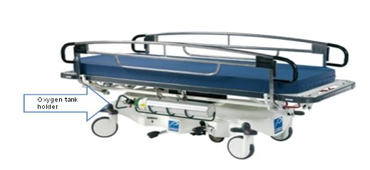
Note: In the healthcare setting having a single stretcher type that services a majority of patient conditions is desired. Patients may use stretchers for transport only, however many patients may also require supporting oxygen during transport to and from diagnostic procedures.
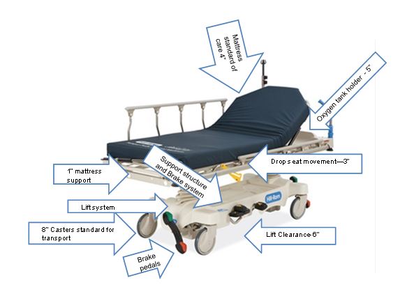
Figure 2: View of Stretcher with Oxygen Tank
Note: Oxygen tanks require a minimum of 5” of vertical height in stretcher configuration
(Picture provided by Stryker)
M301.2.2, M302.2.2 Transfer Size
Proposed requirement:
30" wide minimum and 15" deep minimum
• Sub-Committee Recommendation:
28" wide minimum and 17" deep minimum. This transfer surface is located on the longitudinal (long) side of the stretcher—either right or left side
Rationale: Based upon full committee discussion and harmonization with Exam Table Subcommittee.
M301.2.3 Transfer Sides
Proposed requirement:
The transfer surface shall be located to provide options to transfer from a mobility device onto one short side (depth) and one long side (width) of the surface.
• Sub-Committee Recommendation:
The transfer surface shall be located to provide options to transfer from a mobility device onto both long sides (length), right and left, of the surface.
Rationale: Revision is based upon the configuration and use of stretchers. The configuration of stretchers will not allow for unobstructed access to a transfer surface located at either the foot end or head. The location of the Transfer Side will be located on the patient right or patient left at roughly midway between the foot end and head end. This places the position at a desirable location along the length of the stretcher side so as when the transfer is completed, the patient is in the correct location relative to the articulation of the backrest. As a result, a patient can only access one long side of the transfer surface, the one short side will be inaccessible.
Proposed requirement:
Each transfer side shall provide unobstructed access to the transfer surface.
• Sub-Committee Recommendation:
Each transfer side shall minimize obstructions to the transfer surface. Obstructions shall not be vertically less than 1" (25 mm) nor be horizontally more than 3" (75 mm) from the edge of the patient support surface provide unobstructed access to the transfer surface.
Rationale: The position of obstructions has been discussed by the full committee and the Exam Table subcommittee and has established an obstruction protruding no more than 3" beyond the edge of the transfer surface.
It is proposed herein that an additional requirement be added to restrict how high the obstruction can exist in comparison to the top of the transfer surface. Guidance from IEC 60601-2-52 does establish the maximum vertical obstruction of being not less than 1" below the top of the transfer surface.
M301.3 Transfer Supports
Proposed requirement:
Transfer supports shall be provided for use with the transfer sides required by M301.2.3 and shall comply with M305.2.
• Sub-Committee Recommendation:
No revision.
* Other Transfer Support Dimensions: (*not included in the Proposed Rule)
• Sub-committee Recommendation:
Length - At least 15 inches (300 mm) in length and located on the length of the transfer surface. Located on the opposite side of the access point.
Circular cross sections – Circular cross sections must have an outside diameter of 1¼ inches minimum and 2 inches maximum. Section may be discontinuous (see Rationale) along the length of the Gripping Surface not exceeding 20% of the length of the gripping surface.
o Rationale: Discontinuous allows for the vertical support structure that is necessary for supporting the grip.
Non-circular cross sections - Non-circular cross sections must have a cross section dimension of 2 inches maximum and a perimeter dimension of 4 inches minimum and 4.8 inches maximum. Section may be discontinuous* along the length of the Gripping Surface not exceeding 20% of the length of the gripping surface.
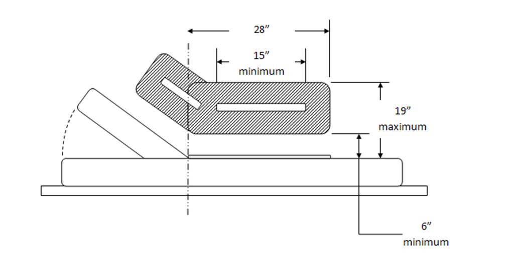
Transfer Supports Position
• Sub-Committee Recommendation:
Located longitudinally within the long side of the of the transfer surface. Transfer support will be located on the opposite side of the transfer side.
Length: Minimum of 15" of continuous support.
o Rationale: This is to accommodate the articulation that is necessary for the head and back support on stretchers.
Height: Located no less than 6 inches (150 mm) and no more than 19 inches (482 mm) above the patient support surface
Horizontal Distance from Transfer Surface: No more than 3 inches (75 mm) from the edge of the patient support surface.
o Rationale: Currently, and it is envisioned that transfer supports will continue to be enabled through the side rail systems currently employed on stretchers. Based on the nature of side rail mechanisms to allow them to fold and store properly. Currently, the state of the art for side rail have them placed just under 3" outboard of the mattress surface edge (transfer surface edge). Therefore, it is requested that this horizontal dimension allow for current designs to fall under the proposed rule.
Figure 3: Transfer Support Location – Plan View
(Drawings designef for Access Board by Stryker)
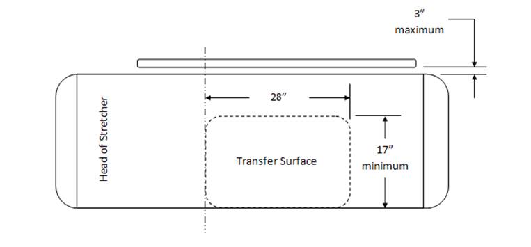
Figure 4: Transfer Support Location – Side View
(Drawings designef for Access Board by Stryker)
M301.3.2 Stirrups
Proposed requirement:
Where stirrups are provided, they shall provide a method of supporting, positioning, and securing the patient’s legs.
• Sub-committee recommendation:
Where stirrups are provided, a method shall be provided for supporting, positioning, and securing the patient’s legs.
Rationale: Stirrups (also called foot supports) alone may not provide a method of supporting, positioning, and securing the patients legs, but may be supplemented by or used in conjunction with a secondary accessory that provides this function. Typical accessory is a set of calf supports that support the patient legs just below the knee. Recommending a slight revision to this wording. When stirrups are provided "A" method shall be provided for supporting, positioning and securing the patient's legs. This wording change allows for alternate methods to be used for this repositioning, etc Full Sub-committee approval for this change.
M301.3.3 Head and Back Support
Proposed requirement:
Where diagnostic equipment used by patients in a supine, prone, or side-lying position, and diagnostic equipment used by patients in a seated position can be adjusted to reclined positions (M301.3.3 and M302.3.3) would require head and back support to be provided throughout the entire range of the incline. This is consistent with ANSI/AAMI HE 75 which recommends that the “support surface needs to be adjustable or have adjustable features (e.g., for the head, neck, back, lumbar region, leg, knees, and foot, as appropriate) to support patients in various postures and body positions in a manner that optimizes their comfort. See ANSI/AAMI HE 75, section 16.4.7 (h. Although not required by the proposed standards, examination tables that can be adjusted to a sitting position and then reclined to a horizontal position may be easier for patients with disabilities to transfer onto and off of than examination tables that are horizontal only.
• Sub-Committee Recommendation:
No revision.
M301.4 Lift Compatibility
M01.4.1 Clearance in Base
Proposed requirement:
The base of the equipment shall provide a clearance 44 inches (1120 mm) wide minimum, 6 inches (150 mm) high minimum measured from the floor, and 36 inches (915 mm) deep minimum measured from the edge of the examination surface. Where the width of the examination surface is less than 36 inches (915 mm), the clearance depth shall extend the full width of the equipment. Equipment components are permitted to be located within 8 inches (205 mm) maximum of the centerline of the clearance width.
• Sub-Committee Recommendation:
The base of the equipment shall provide a clearance 39 inches (1000 mm) wide minimum, 6 inches (150 mm) high minimum measured from the floor, and 36 inches (915 mm) deep minimum measured from the edge of the examination surface. Where the width of the examination surface is less than 36 inches (915 mm), the clearance depth shall extend the full width of the equipment. Equipment components are permitted to be located within 8 inches (205 mm) maximum of the centerline of the clearance width.
Rationale: Harmonization with IEC 60601-2-52 "Particular requirements for the basic safety and essential performance of medical beds" Change clearance requirement to:
39 inches (1000 mm) from 44 inches (1120 mm). This is the current International standard for clearance. Recommend that this be harmonious with this standard.
For stretchers with a shorter wheelbase than “standard” size stretcher bases, the clearance for a lift may include a lift window that is a combination of “Clearance in Base” and “Clearance Around Base”. With a short wheelbase, one leg of a floor based mobile patient lift will be placed through the base and the second leg of the lift will be placed around the base. The size of the window should still apply as written, these comments are placed here to identify a difference in how product configuration should not affect the clause.
IEC 60601-2-52 Particular requirements for the basic safety and essential performance of medical beds provides a similar requirement for lift clearance in the base. The dimensions there are 150mm x 1000mm. Recommendation here is to shrink the 1120mm dimension to 1000mm (39”) dimension to harmonize with the international standard.
M302 Diagnostic Equipment Used by patients in Seated Position
• Sub-Committee Recommendation
May be seen as applying to some versions of “Stretcher Chairs” used in Emergency Departments. These include products produced by Stryker, Hausted, Transmotion, etc.
Recommendation is that this section does not include “non-clinical” products (general chairs and/or recliners) used to support patients in a sitting position in “Fast Track”, “Urgent Care” or Triage settings.
It is important to create a distinction in the definition of these products so as to ensure that clinical products such as Examination Chairs and Stretcher Chairs fall under the extent of the rule, but that General Chair Seating or Recliners do not fall under the extent of the rule. Discussion regarding if stretchers fall under this criteria. Stretchers have a head & back support that keep the patient in a semi-reclined position, however the patients legs are not in a dependent position such as that when sitting in a chair. Stretchers are accessed when the stretcher is in a flattened position. Recommend that stretchers not be included in Diagnostic Equipment used by patients in a seated position.
M302.2 Transfer Surface
M302.2.3 Transfer Sides
Proposed requirement:
The transfer surface shall be located to provide options to transfer from a mobility device onto one short side (depth) and one long side (width) of the surface.
• Sub-Committee Recommendation: No revision as a stretcher chair should be the equivalent of a mobile examination chair.
M305.2 Transfer Supports
M305.2.2 Transfer Supports Structural Strength
Proposed requirement:
Transfer supports and their connections shall be capable of resisting vertical and horizontal forces of 250 pounds (1,112 N) applied at all points on the transfer support.
• Sub-Committee Recommendation:
Transfer supports and their connections shall be capable of resisting vertical and horizontal forces of 250 pounds (1,112 N) applied at the worst case accessible location without creating an unacceptable risk.
Rationale: Manufacturer shall determine the worst case accessible location(s) and test at these locations.
Acceptance criteria must be defined. It is understood that the Transfer Support will deform to some degree under these loads. This clause should limit elastic deformation and prohibit permanent deformation or breakage.
Possible language as modified from IEC 60601-2-52: “Transfer Supports shall be designed to withstand the forces applied during reasonably foreseeable use without creating an unacceptable RISK.”
As manufactures of medical equipment, ISO 14971 “Application of risk management to medical devices” is a commonly adhered to standard. As a result, product development normally includes the application of risk management practices and will consequently define “unacceptable risk” as it applies here.
M305.2.3 Fittings
Proposed requirement:
Transfer supports shall not rotate within their fittings
• Sub-Committee Recommendation:
Transfer supports shall not rotate within their fittings, when in the use or latched position, to the point of creating an unacceptable risk when subjected to the load conditions as prescribed in M305.2.2.
Rationale: It is understood that transfer supports will be of varying configuration and designs. Some may be removable, some foldable or articulating. In these cases, it may be advantageous to allow them to rotate, translate, fold, etc. but they should not do so at loads below those prescribed in M305.2.2.
References
IEC 60601-2-52 "Particular requirements for the basic safety and essential performance of medical beds"
ANSI/AAMI HE 75, section 16.4.7 (h.
User Comments/Questions
Add Comment/Question