Recommendations on Standards for the Design of Medical Diagnostic Equipment for Adults with Disabilities, Advisory Committee Final Report
5.4 Transfer Supports Recommendations
5.4.1 Transfer Support Location for M301 and M302
Description: Transfer supports assist individuals while making transfers on to the transfer area. Provisions require transfer supports be provided for use with the transfer sides and be located within reach of the transfer surface and not obstruct transfer onto the surface when in position.
NPRM Proposed Provision: M305.2.1 Location. Transfer supports shall be located within reach of the transfer surface and shall not obstruct transfer onto or off the surface when in position.
NPRM Preamble Discussion: The transfer support would be located on the side of the transfer surface that is opposite the transfer side (M301.2.3 and M302.2.3) similar to the provisions in the 2010 Standards for grab bars provided at bathtubs and shower compartments with seats. This would be a minimum requirement. Where possible, it is recommended that supports be provided on each side of the transfer surface that is 15 inches deep minimum for patients to maintain position after they have transferred onto the equipment, and that the supports be repositionable to permit transfer.
The Committee recommends transfer supports be required on both sides of the transfer surface and be movable or removable so the supports are out of way during transfer.
Rationale for the recommendation
Transfer supports or handholds on adjustable medical equipment facilitate transfers onto a transfer surface by giving the individual something to hold or grab onto while transferring. This recommendation for placement of the supports on both sides of the equipment will increase options during patient transfers.
Figure 5.4.1 Location and Length of Transfer Supports
(SOURCE: Midmark Corporation)
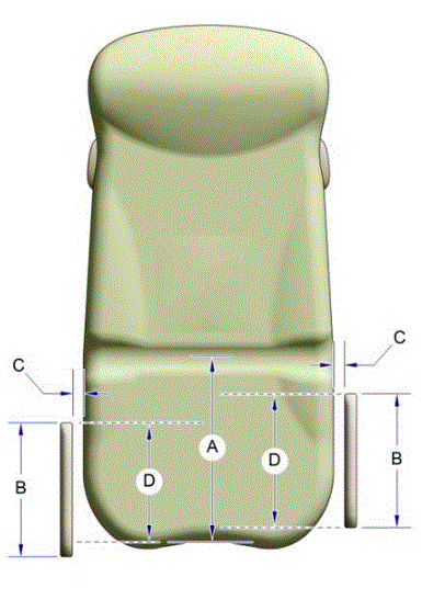
A: Table seat depth, 17 inches minimum
B: Transfer support length, 15 inches minimum
C: Distance between transfer support and transfer surface, 1 1/2" maximum
D: Minimum 80% overlap between the transfer support and transfer surface, 12” minimum*
* Note: The 80% overlap allows for the transfer support to be slightly forward or back of the front edge of the transfer surface
5.4.1.1 Transfer Support Location Recommendation for Stretchers
For Stretchers, the transfer surface is oriented along the long side of the surface.
Rationale for the recommendation
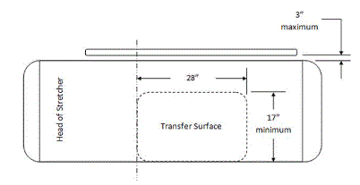
Patients access stretchers on either of the long sides rather than on its end (short side). The Committee proposes to flip the orientation of the transfer surface so that the long side of the transfer support is along the long side of the stretcher. This reflects the actual use since accessing it on the end (short side) would require scooting, sliding, or twisting a long distance to lie in the proper position on the stretcher. Transfer support will be located on the opposite side of the transfer side. (see Figure 5.4.1.1)
Figure 5.4.1.1 Transfer Support Location – Plan View
(SOURCE: Stryker Medical)
5.4.1.2 Transfer and Positioning Support Location Recommendations for Imaging Equipment with Transfer Surfaces
For imaging equipment with transfer surfaces, the Committee recommends adding transfer supports on tables with transfer depths of less than or equal to 24 inches and positioning supports for transfer depths greater than 24 inches. Both transfer and positioning supports are to be located opposite the transfer side.
Rationale for the recommendation
Imaging tables need some form of support on the opposite side of the table. Because of the size, diversity, and use of diagnostic imaging tables, this support will carry out different functions on different tables. The function dictates the design and load capability. This two-part recommendation recognizes the different use of the supports based on table width. The Committee used a 24-inch dividing point for table width to accommodate the dimensions for the maximum reach range.
For transfer surface depths on tables less than 24 inches wide, a transfer support must be available on the side opposite the entry to the transfer surface. Some imaging tables are narrow and may not have additional “table” surface beyond the transfer depth. For these narrow tables, a more substantial transfer support is necessary. This transfer support facilitates transfers and prevents patient falls over the opposite side of the table.
For transfer surface depths on tables greater than 24 inches wide, a positioning support must be available on the side opposite the entry to the transfer surface. For wider tables, a transfer support would not be functional because of its distance from the patient. If transfer is possible from either of the long sides of the table, then a positioning support must be available on the side opposite the transfer.
A positioning support requires a different load bearing capacity than a transfer support. Minimum load bearing requirements for supports are found in international standards (e.g. risk management ISO 14971; IEC60601-1; and use of IEC60601-2-52.) Generally, for positioning supports, the table is supporting the full weight of the patient rather than the support. In this situation, the load bearing requirements of the positioning support impose a different load rating. The location of this positioning support must accommodate the clinical use along with the patient’s positioning needs.
In some cases, current methods of imaging patients require table design that may not permit supports to attach to the table without compromising the diagnostic functionality of the table and/or requiring complete redesign of the table structural support. Some types of modalities capture images by using a table that moves. In those cases, attaching supports would likely impede the required movement. For example, some x-ray tables require bi-directional horizontal movement to perform the functions for the images. A new generation of equipment is necessary to address this.
Many/most imaging tables have a moving part and a stationary part dictated by diagnostic need. Many also move up and down. The tables must safely accommodate a wide range of patient sizes. These considerations factor into where the substantial support structure is located while still enabling the precise movement and imaging transparency of the table top/cradle. Therefore, in many cases, there currently is no feasible direct attachment point on the table for a support.
Any support design must take into consideration the risks associated with IV or other tubing, monitors and other such items entangling in the support as the table moves during the procedure. Support design must also assure sufficient clinician access to the patient during the exam for proper positioning, administration of imaging agents or drugs, patient monitoring, etc.
5.4.2 Transfer Support Length for M301 and M302
Description: Transfer support length applies to the gripping surface of the support, that portion of the support used to grasp or maintain balance against while performing a transfer. The purpose of a minimum length is to ensure that there is a minimum gripping surface available to support positioning and repositioning during a transfer. This is a linear measurement (see Figure 5.4.1).
NPRM Proposed Provision: Length not addressed.
NPRM Preamble Discussion: The Access Board is considering whether the following technical criteria would be appropriate for the location and size of transfer supports. The transfer support would extend horizontally the entire depth of the transfer surface and would be 15 inches minimum in length.
The Committee recommends 15 inches minimum length positioned so that the transfer support overlaps the minimum depth of the transfer surface by 80%.
Rationale for the recommendation
The length of the transfer support shall be a minimum of 15 inches long and positioned so that the transfer support overlaps the length of the transfer surface by 80% at a maximum distance from the transfer surface of 1½ inches. (See Figure 5.4.1).
5.4.2.1 Transfer Support Length Recommendation for Stretchers
On Stretchers, the transfer surface is oriented along the long dimension of the surface on which patients are positioned in the supine, prone, or side-lying position (see Figure 5.4.1.1).
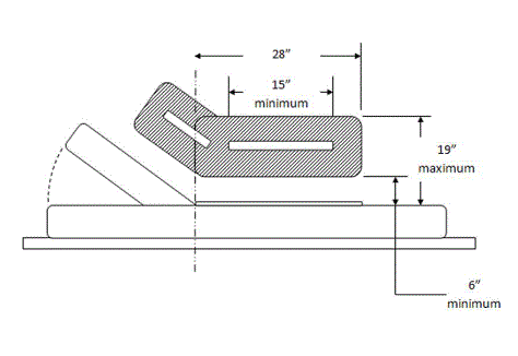
For Stretchers, the Committee recommends transfer supports be 15 inches minimum length.
Rationale for the recommendation
The length provides continuous support for patients using the stretchers. This is to accommodate the articulation that is necessary for the head and back support on stretchers.
Figure 5.4.2.1 Transfer Support Location – Side View
(SOURCE: Stryker Medical)
5.4.2.2 Transfer and Positioning Support Length Recommendations for Imaging Equipment with Transfer Surfaces
On imaging equipment with transfer surfaces, the transfer surface is oriented along the long dimension of the surface on which patients are positioned in the supine, prone, or side-lying position (see Figure 5.2.1.4).
For imaging equipment with transfer surfaces, the Committee recommends a transfer support be 28 inches minimum length and that a positioning support be 12 to 16 inches in length.
Rational for the recommendation
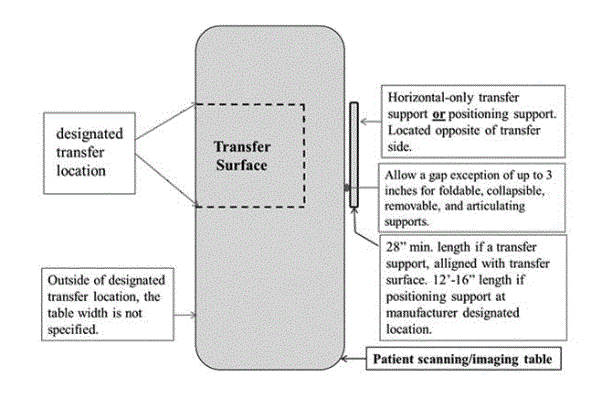
A transfer support (for transfer surfaces less than or equal to 24” deep) is to extend horizontally along the side of the patient scanning/imaging table at least the minimum width of the transfer surface, a minimum length of 28-inches. It is to be located at the designated transfer location.
A positioning support (for transfer surfaces >24” deep) is to extend horizontally along the side of the patient scanning/imaging bed/table with a length of 12 to 16 inches and a height of 3 to 6 inches above the surface. It will be located at a position to accommodate the clinical use, with design inputs from users, for optimal positioning assistance.
Either a transfer support or positioning support may need to be separate from the patient-imaging table in cases where its attachment to the table is not possible. Specific discussion of these situations is in Section 7.
The two-part standard addresses various widths of tables. (see Section 5.4.1.2).
5.4.2.2 Schematic of Transfer Surface and Patient Support for Diagnostic Imaging Equipment
(SOURCE: GE Healthcare)
5.4.3 Transfer Support Height for M301 and M302
Description: Transfer support height applies to the vertical distance that the gripping area of the support is above the transfer surface (see Figure 5.4.3). The purpose of a minimum height is to ensure that the gripping surface is at an adequate height to facilitate positioning during a transfer.
NPRM Proposed Provision: Height not addressed.
NPRM Preamble Discussion: The Access Board is considering whether 6 inches minimum and 19 inches maximum above the transfer surface would be an appropriate height for transfer supports on diagnostic equipment used by patients in a supine, prone, or side-lying position, and diagnostic equipment used by patients in a seated position. The minimum height is consistent with the information provided by Midmark Corporation on examination tableside rails, and the maximum height is generally consistent with the height of grab bars above shower seats in the 2010 Standards.
The Committee recommends following the Access Board’s proposed height of 6 to 19 inches from the top of the transfer surface for transfer supports.
Rationale for the recommendation
The location of the transfer supports shall be a minimum of 6 inches to a maximum of 19 inches from the top of the transfer surface. Members of the committee also discussed IEC 60601-2-52, which defines specific requirements to prevent entrapment safety hazards on specific types of MDE (typically hospital beds and stretchers). Manufacturers of such equipment on the committee determined that this recommendation did not conflict with IEC 60601-2-52, allowing equipment to be designed to provide both accessibility and safety from entrapment hazards. The Committee also discussed height adjustability where equipment functions allow for adjustability of the transfer supports as this will increase design options as a best practice.
Figure 5.4.3 Height of Transfer Supports
(SOURCE: Midmark Corporation)
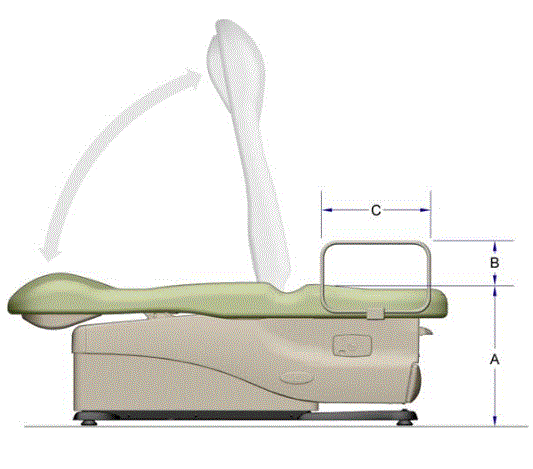
B: 6 inches minimum and 19 inches maximum from the top of the transfer surface
C: Transfer support length, 15 inches minimum
5.4.3.1 Positioning Support Height Recommendation for Imaging Equipment with Transfer Surfaces
For imaging equipment with transfer surfaces, the Committee recommends a positioning support 3 to 6 inches above the transfer surface.
Rationale for the recommendation
See above discussion on transfer supports for imaging equipment with transfer surfaces in Section 5.4.2.2. Manufacturers must locate the supports at a position designated for optimal positioning assistance.
5.4.4 Transfer Support Distance from Transfer Surface Recommendations for M301 and M302
Description: This minimum distance ensures that the transfer support is within reach of the transfer surface and can be effectively used to position during a transfer. The gripping surface measurement is horizontal from the adjacent edge of the transfer surface (see figure 5.4.1).
NPRM Proposed Provision: M305.2.1 Location. Transfer supports shall be located within reach of the transfer surface and shall not obstruct transfer onto or off the surface when in position.
NPRM Preamble Discussion: The Access Board is considering whether the following technical criteria would be appropriate for the location and size of transfer supports on diagnostic equipment used by patients in a supine, prone or side-lying position, and diagnostic equipment used by patients in a seated position:
-
At least one transfer support would be provided on the side of the transfer surface that is 15 inches deep minimum. The transfer support would be located on the side of the transfer surface that is opposite the transfer side (see M301.2.3 and M302.2.3) similar to the provisions in the 2004 ADA and ABA Accessibility Guidelines for grab bars provided at bathtubs and shower compartments with seats. This would be a minimum requirement. Where possible, it is recommended that supports be provided on each side of the transfer surface that is 15 inches deep minimum for patients to maintain position after they have transferred onto the equipment, and that the supports be repositionable to permit transfer.
-
The transfer support would extend horizontally the entire depth of the transfer surface and would be 15 inches minimum in length.
-
The gripping surface of the transfer support should be located 1 ½ inches maximum measured horizontally from the adjacent edge of the transfer surface. This would ensure that the transfer support is within reach and can be effectively used during transfers.
The above technical criteria would likely result in the transfer surface being located at the foot end of examination tables and allow the use of transfer supports similar to the side rails described in the information provided by Midmark Corporation.
The Committee recommends the transfer supports be located at a maximum distance from transfer surface of 1 ½ inches.
Rationale for the recommendation
The Committee followed the NPRM proposal.
Refer back to Figure 5.4.1 Location and Length of Transfer Supports.
5.4.4.1 Transfer Support Distance from Transfer Surface Recommendation for Stretchers
The Committee recommends locating the transfer support along the long side of the of the transfer surface on the opposite side of the transfer. The horizontal distance from transfer surface should be no more than 3 inches from the edge of the patient support surface.
Rationale for the recommendation
Currently transfer supports are part of the side rail system on stretchers. To allow the side rail system to fold and store properly, the rails must be at a little less than 3 inches beyond the mattress surface edge (transfer surface edge). The Committee proposes that this horizontal dimension be included for stretchers under the proposed rule.
5.4.4.2 Transfer Support Distance from Transfer Surface Recommendation for Imaging Equipment
The Committee recommends a maximum distance of 1 1/2 inches from the transfer surface to the support (either transfer or positioning). The distance may extend up to 3 inches where the support must fold, collapse, come off, or articulate.
Rationale for the Recommendation
The Committee decided to follow the recommended 1 1/2inch proposal but included a 3-inch dimension to accommodate movement of the support. This standard parallels the recommendation for stretchers (see Figure 5.4.1.1).
5.4.5 Transfer Support Position Recommendation for M301 and M302
Description: Transfer support position refers to the placement of the gripping surface within the minimum and maximum vertical height ranges proposed. It addresses angled supports or contoured portions of horizontal supports often provided for ergonomics or equipment design considerations. This provision would apply along the support length and not to the cross-sectional profile of the gripping surface, see Figure 5.4.1.1.
NPRM Proposed Provision: position not addressed.
NPRM Question 17 e): Should angled or vertical transfer supports be permitted?
The Committee recommends a gripping surface be located within the minimum and maximum heights.
Rationale for the recommendation
The design process will determine the shape (contours and curves along length for ergonomics, not cross sectional profile) so that manufacturers can use creativity and flexibility as to the direction of positioning (i.e. horizontal, angled, etc.).
5.4.5.1 Transfer and Positioning Support Position Recommendation for Imaging Equipment
On imaging equipment, the transfer surface is oriented along the long dimension of the surface where patients lie in a supine, prone, or side-lying position (see Figure 5.4.2.2).
On imaging equipment with transfer surfaces, the transfer or positioning support must be oriented horizontally.
Rationale for the recommendation
A transfer support will extend horizontally along the side of the patient scanning/imaging table at least the minimum width of the transfer surface, but in all cases 28 inches minimum. It will be located at the designated transfer location.
A positioning support will extend horizontally along the side of the patient scanning/imaging bed/table and be 12 - 16 inches in length and 3 - 6 inches above the transfer surface. It will be located at a position designated by the manufacturer for optimal positioning assistance.
(see Figure 5.4.2.2 Schematic of Transfer Surface Size and Patient Support for Diagnostic Imaging Equipment)
5.4.6 Transfer Support Gripping Surface Cross Section and Clearances for M301, M302, and M305.2
Description: This provision prescribes a cross-sectional profile of the transfer support sufficient to enable individuals with disabilities to firmly grasp the gripping surface and support themselves during transfers. The provision addresses gripping surface diameter and perimeter of the support.
NPRM Proposed Provision: gripping surface cross section not addressed.
NPRM Preamble Discussion: The 2010 Standards specify the following dimensions for grab bars to enable individuals with disabilities to firmly grasp the grab bars and support themselves during transfers:
-
Grab bars with circular cross sections must have an outside diameter of 1¼ inches minimum and 2 inches maximum.
-
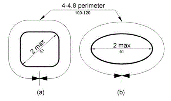
Grab bars with non-circular cross sections must have a cross section dimension of 2 inches maximum and a perimeter dimension of 4 inches minimum and 4.8 inches maximum.
The Access Board is considering whether the above cross section dimensions would be appropriate for the gripping surfaces of transfer supports on diagnostic equipment used by patients in a supine, prone, or side-lying position, and diagnostic equipment used by patients in a seated position.
The Committee recommends following the provisions for gripping surface cross section configurations contained in the 2010 Standards.
Rationale for the recommendation
The cross section dimensions contained in the 2010 Standards used for grab bars found in the built environment are those contemplated for use in MDE. The Committee expressed confidence in reliance on the cross-section dimensions in the 2010 Standards. Allowing both noncircular cross sections and circular cross sections gives manufacturers flexibility to employ the best configuration for use of the equipment, hand, grip strength, and power grab functions. While a majority of the Committee members supported a recommendation allowing both noncircular and circular cross sections, some members noted ergonomic considerations support the better functionality of circular cross section gripping surface.
Figure 5.4.6(a) Gripping Surface Circular Cross Section
(SOURCE: U.S. Access Board)
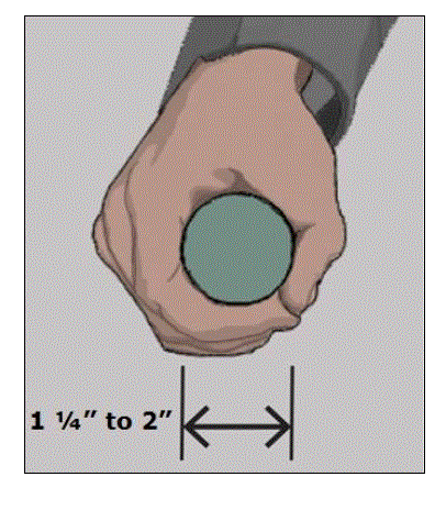
Figure 5.4.6(b) Gripping Surface Non-Circular Cross Section
(SOURCE: U.S. Access Board)
5.4.7 Transfer Support Gripping Surface Clearance Recommendation for M301 and M302
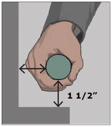
Description: A clearance around the gripping surface is necessary to ensure sufficient space for a person to grasp the transfer support. This clearance would allow the fingers and knuckles to clear adjacent equipment parts as they grip the support. This clearance location is around the cross section of the gripping surface (see Figure 5.4.7).
NPRM Proposed Provision: Gripping surface clearance not addressed.
NPRM Preamble Discussion: The Access Board is considering whether 1½ inches minimum clearance around the gripping surface would be appropriate for transfer supports on diagnostic equipment used by patients in a supine, prone, or side-lying position, and diagnostic equipment used by patients in a seated position.
The Committee recommends following the Access Board’s proposal in the preamble discussion allowing a 1½-inch clearance.
Rationale for the recommendation
As above, this provision is based on precedent of 2010 Standards and International Building Code Requirements (ICC/ANSI A117.1). The Committee found no reason to change this requirement for MDE.
Figure 5.4.7 Gripping Surface Clearance
(SOURCE: U.S. Access Board)
5.4.8 Transfer Support Gripping Surface Hazard Recommendation for M301 and M302
Description: Gripping surface hazards are sharp or abrasive elements that prevent an individual from sufficiently grasping the support and may pose an injury hazard during use. The provision would prevent such hazards.
NPRM Proposed Provision: Gripping surface hazards not addressed.
NPRM Preamble Discussion: Did not address.
The Committee recommends gripping surfaces be free of sharp or abrasive elements and have rounded edges.
Rationale for the recommendation
Gripping surface configurations must provide an effective and safe surface for patients to hold onto. Sharp edges or abrasive elements may injure and cause the patient to lose his/her grip during positioning or transfer. This provision, like those above, originates in the technical provisions for grab bars in the 2010 Standards
5.4.9 Interruptions along Transfer Support Gripping Recommendation for M301 and M302
Description: Transfer supports may contain elements to provide structural support or prevent patient entrapment. The elements, bars, pickets, spacers, panels, and similar features, connect to the transfer support and may interrupt the gripping surface. At the point of connection, these features impede the ability to grasp completely around the cross section of the gripping surface. The proposed provision seeks to balance the need for such features with an adequately usable transfer support.
NPRM Proposed Provision: Interruptions along gripping surface not addressed.
NPRM Preamble Discussion: Did not address.
The Committee recommends the bottom of the transfer support have no obstructions affecting more than 20% of its length.
Rationale for the recommendation
This recommendation assures that patients needing the use of the transfer support can easily grip the support. Gaps or interruptions along the bottom of the transfer surface may not obstruct more than 20% of its length per the 2010 Standards. Section 505.6 specifies that the gripping surface on the vertical support structure that is necessary for supporting the grip must not be discontinuous.
5.4.10 Transfer Support Fittings Recommendations for M301 and M302
Description: To ensure safe and effective transfers, transfer supports must not rotate within their fittings during use. The proposed provision uses technical criteria in the 2010 Standards for grab bars.
NPRM Proposed Provision: M305.2.3 Fittings. Transfer supports shall not rotate within their fittings.
The Committee recommends transfer supports not rotate when locked in place for patient transfer or use.
Rationale for the recommendation
Transfer supports that move when locked for use would create an unacceptable risk for patients relying on stable support. When the transfer supports latch into a locked position, the transfer supports must meet the required load conditions without movement.
To be useful, transfer supports will be of varying configuration and designs. Some may be removable, some foldable or articulating. In these cases, it is advantageous to allow the supports to perform needed movement but they should not do so when locked at loads below those prescribed in M305.2.2.
5.4.11 Transfer Support Structural Strength Recommendations for M301 and M302
Description: Transfer supports and their connections must be capable of resisting sufficient vertical and horizontal forces to remain stable during use. The proposed provision addresses these aspects of structural strength.
NPRM Proposed Provision: M305.2.2 Structural Strength. Transfer supports and their connections shall be capable of resisting vertical and horizontal forces of 250 pounds (1,112 N) applied at all points on the transfer support.
The Committee recommends transfer supports and connections contain the strength to resist vertical and horizontal forces of 250 pounds at locations determined by the intended use of the equipment.
Rationale for the recommendation
The Committee recommends a proposal that harmonizes the transfer support requirements with other provisions for transfer supports. The proposed technical criteria originated from provisions for grab bars in the 2010 Standards. During discussion manufacturers stated that industry is required to test the most vulnerable spots on the transfer support. Industry must follow testing parameters found in other standards. IEC60601-2-52: “Transfer Supports shall be designed to withstand the forces applied during reasonably foreseeable use without creating an unacceptable RISK.” Transfer supports will deform to some degree under these loads, it must remain stable enough for use. This clause should limit elastic deformation and prohibit permanent deformation or breakage. Product development manufacturers use risk management practices to avoid any unacceptable risk defined by the specific product designs. The most commonly followed standard for risk management is ISO 14971.

User Comments/Questions
Add Comment/Question