36 CFR Part 1194 - Proposed Information and Communication Technology (ICT) Standards and Guidelines NPRM
407 Operable Parts
407.1 General.
Where provided, operable parts of ICT shall conform to 407.
407.2 Contrast.
Where provided, keys and controls shall contrast visually from background surfaces. Characters and symbols shall contrast visually from background surfaces with either light characters or symbols on a dark background or dark characters or symbols on a light background.
407.3 Tactilely Discernible.
At least one tactilely discernible input control shall be provided for each function and shall conform to 407.3.
EXCEPTION: Devices for personal use with input controls that are audibly discernable without activation and operable by touch shall not be required to be tactilely discernible.
407.3.1 Identification.
Input controls shall be tactilely discernible without activation and operable by touch. Where provided, key surfaces outside active areas of the display screen shall be raised above surrounding surfaces.
407.3.2 Alphabetic Keys.
Where provided, individual alphabetic keys shall be arranged in a QWERTY keyboard layout and the “F” and “J” keys shall be tactilely distinct from the other keys. Where the ICT provides an alphabetic overlay on numeric keys, the relationships between letters and digits shall conform to ITU-T Recommendation E.161 (incorporated by reference in Chapter 1).
407.3.3 Numeric Keys.
Where provided, numeric keys shall be arranged in a 12-key ascending or descending keypad layout. The number five key shall be tactilely distinct from the other keys.
407.4 Key Repeat.
Where a keyboard with key repeat is provided, the delay before the key repeat feature is activated shall be fixed at, or adjustable to, 2 seconds minimum.
407.5 Timed Response.
Where a timed response is required, the user shall be alerted visually, as well as by touch or sound, and shall be given the opportunity to indicate that more time is needed.
407.6 Status Indicators.
Status indicators, including all locking or toggle controls or keys (e.g., Caps Lock and Num Lock keys), shall be discernible visually and by touch or sound.
407.7 Color.
Color coding shall not be used as the only means of conveying information, indicating an action, prompting a response, or distinguishing a visual element.
407.8 Audio Signaling.
Audio signaling shall not be used as the only means of conveying information, indicating an action, or prompting a response.
407.9 Operation.
At least one mode of operation shall be operable with one hand and shall not require tight grasping, pinching, or twisting of the wrist. The force required to activate operable parts shall be 5 pounds (22.2 N) maximum.
407.10 Privacy.
The same degree of privacy of input and output shall be provided to all individuals. When speech output required by 402.2 is enabled, the screen shall not blank automatically.
407.11 Keys, Tickets, and Fare Cards.
Where keys, tickets, or fare cards are provided, keys, tickets, and fare cards shall have an orientation that is tactilely discernible if orientation is important to further use of the key, ticket, or fare card.
407.12 Reach Height.
At least one of each type of operable part of stationary ICT shall be at a height conforming to 407.12.2 or 407.12.3 according to its position established in 407.12.1 for a side reach or a forward reach.
407.12.1 Vertical Reference Plane.
Operable parts shall be positioned for a side reach or a forward reach determined with respect to a vertical reference plane. The vertical reference plane shall be located in conformance to 407.12.2 or 407.12.3.
407.12.1.1 Vertical Plane for Side Reach.
Where a side reach is provided, the vertical reference plane shall be 48 inches (1220 mm) long minimum.
407.12.1.2 Vertical Plane for Forward Reach.
Where a forward reach is provided, the vertical reference plane shall be 30 inches (760 mm) long minimum.
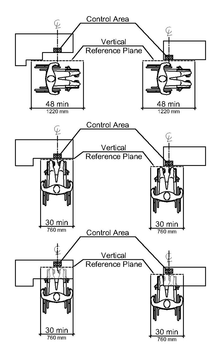
Figure 407.12.1
407.12.2 Side Reach.
Operable parts of ICT providing a side reach shall conform to 407.12.2.1 or 407.12.2.2. The vertical reference plane shall be centered on the operable part and placed at the leading edge of the maximum protrusion of the ICT within the length of the vertical reference plane. Where a side reach requires a reach over a portion of the ICT, the height of that portion of the ICT shall be 34 inches (865 mm) maximum.
407.12.2.1 Unobstructed Side Reach.
Where the operable part is located 10 inches (255 mm) or less beyond the vertical reference plane, the operable part shall be 48 inches (1220 mm) high maximum and 15 inches (380 mm) high minimum above the floor.
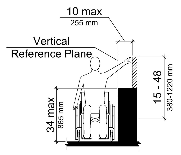
Figure 407.12.2.1
407.12.2.2 Obstructed Side Reach.
Where the operable part is located more than 10 inches (255 mm), but not more than 24 inches (610 mm), beyond the vertical reference plane, the height of the operable part shall be 46 inches (1170 mm) high maximum and 15 inches (380 mm) high minimum above the floor. The operable part shall not be located more than 24 inches (610 mm) beyond the vertical reference plane.
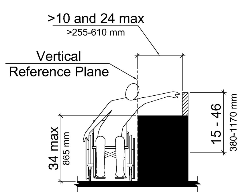
Figure 407.12.2.2
407.12.3 Forward Reach.
Operable parts of ICT providing a forward reach shall conform to 407.12.3.1 or 407.12.3.2. The vertical reference plane shall be centered, and intersect with, the operable part. Where a forward reach allows a reach over a portion of the ICT, the height of that portion of the ICT shall be 34 inches (865 mm) maximum.
407.12.3.1 Unobstructed Forward Reach.
Where the operable part is located at the leading edge of the maximum protrusion within the length of the vertical reference plane of the ICT, the operable part shall be 48 inches (1220 mm) high maximum and 15 inches (380 mm) high minimum above the floor.
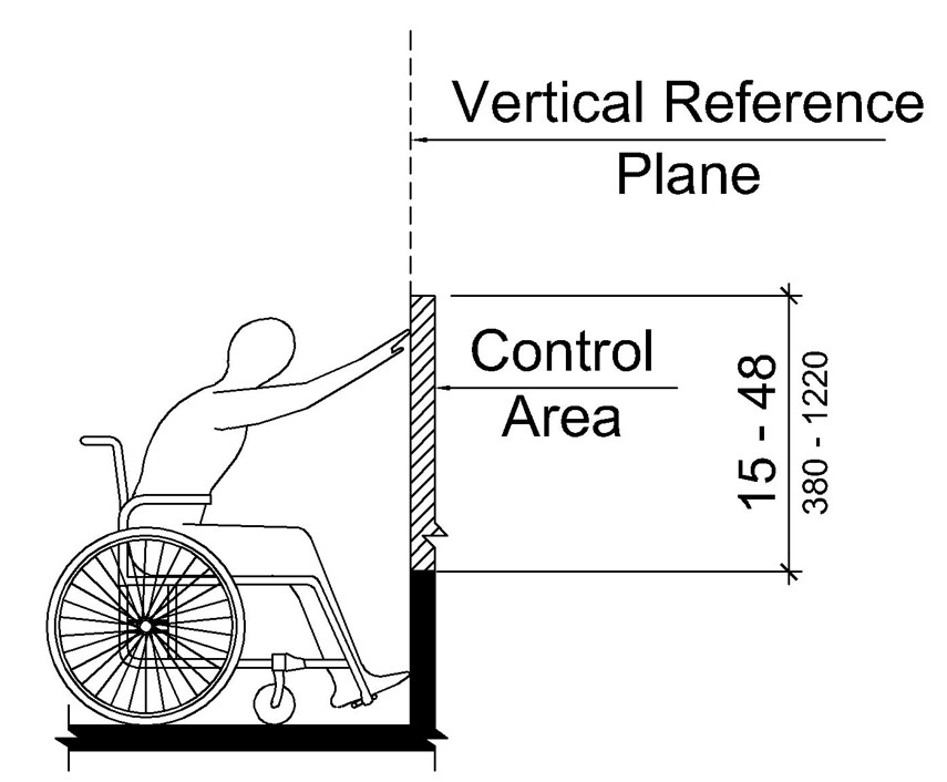
Figure 407.12.3.1
407.12.3.2 Obstructed Forward Reach.
Where the operable part is located beyond the leading edge of the maximum protrusion within the length of the vertical reference plane, the operable part shall conform to 407.12.3.2. The maximum allowable forward reach to an operable part shall be 25 inches (635 mm).

Figure 407.12.3.2
407.12.3.2.1 Height.
The height of the operable part shall conform to Table 407.12.3.2.1.
Table 407.12.3.2.1 Operable Part Height

[Click image above to view HTML version]
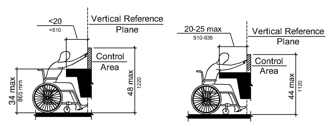
Figure 407.12.3.2.1
407.12.3.2.2 Knee and Toe Space.
Knee and toe space under ICT shall be 27 inches (685 mm) high minimum, 25 inches (635 mm) deep maximum, and 30 inches (760 mm) wide minimum and shall be clear of obstructions.
EXCEPTIONS:1. Toe space shall be permitted to provide a clear height of 9 inches (230 mm) minimum above the floor and a clear depth of 6 inches (150 mm) maximum from the vertical reference plane toward the leading edge of the ICT.
2. At a depth of 6 inches (150 mm) maximum from the vertical reference plane toward the leading edge of the ICT, space between 9 inches (230 mm) and 27 inches (685 mm) minimum above the floor shall be permitted to reduce at a rate of 1 inch (25 mm) in depth for every 6 inches (150 mm) in height.
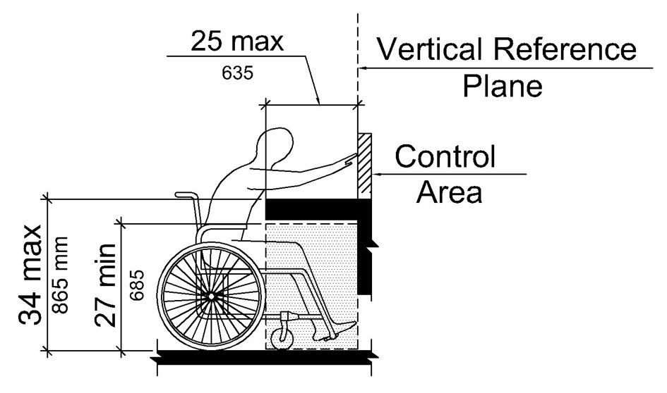
Figure 407.12.3.2.2
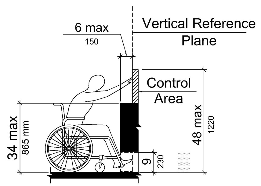
Figure 407.12.3.2.2 Exception 1
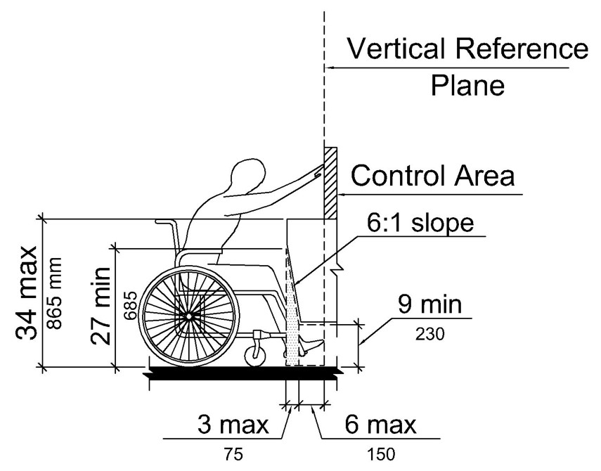
Figure 407.12.3.2.2 Exception 2
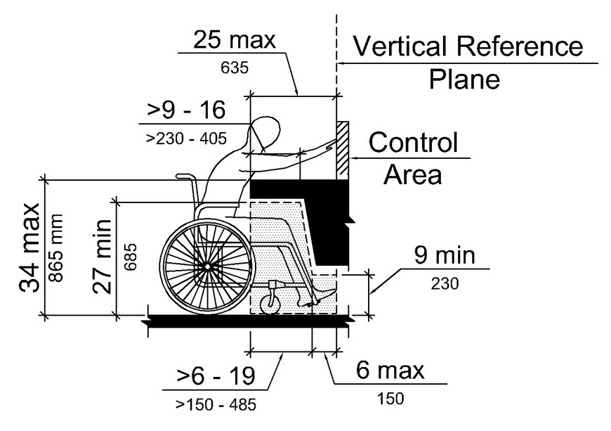
Figure 407.12.3.2.2 with both Exceptions applied
User Comments/Questions
Add Comment/Question