2016 California Standards for Accessible Design Pocket Guide - Eff. Jan. 1, 2017
DIVISION 7: COMMUNICATION ELEMENTS AND FEATURES
11B-701 General.
11B-701.1 Scope. The provisions of Division 7 shall apply where required by Division 2 or where referenced by a requirement in this chapter.
11B-702 Fire alarm systems.
11B-702.1 General. Fire alarm systems shall have permanently installed audible and visible alarms complying with NFPA 72 and Chapter 9, Sections 907.5.2.1 and 907.5.2.3.
[2010 ADAS] 702.1 General. Fire alarm systems shall have permanently installed audible and visible alarms complying with NFPA 72 (1999 or 2002 edition) (incorporated by reference, see "Referenced Standards" in Chapter 1), except that the maximum allowable sound level of audible notification appliances complying with section 4-3.2.1 of NFPA 72 (1999 edition) shall have a sound level no more than 110 dB at the minimum hearing distance from the audible appliance. In addition, alarms in guest rooms required to provide communication features shall comply with sections 4-3 and 4-4 of NFPA 72 (1999 edition) or sections 7.4 and 7.5 of NFPA 72 (2002 edition).
Exception: Reserved.
[2010 ADAS] EXCEPTION: Fire alarm systems in medical care facilities shall be permitted to be provided in accordance with industry practice.
ETA Editor's Note
The 110 dB limit for audible alarms required at 2010 ADAS 702.1 is included at CBC 907.5.2.1.2.
The non-specific variance allowed for medical care facilities by the 2010 ADAS 702.1 Exception is addressed in greater detail at CBC Chapter 9, Section 907 - Fire Alarm and Detection Systems (full contents not included in this Pocket Guide, only sections adopted by DSA-AC).
11B-703 Signs.
11B-703.1 General. Signs shall comply with Section 11B-703. Where both visual and tactile characters are required, either one sign with both visual and tactile characters, or two separate signs, one with visual, and one with tactile characters, shall be provided.
11B-703.1.1 Plan review and inspection. Signs as specified in Section 11B-703, or in other sections of this code, when included in the construction of new buildings or facilities, or when included, altered or replaced due to additions, alterations or renovations to existing buildings or facilities, and when a permit is required, shall comply with Sections 11B-703.1.1.1 and 11B-703.1.1.2.
11B-703.1.1.1 Plan review. Plans, specifications or other information indicating compliance with these regulations shall be submitted to the enforcing agency for review and approval.
11B-703.1.1.2 Inspection. Signs and identification devices shall be field inspected after installation and approved by the enforcing agency prior to the issuance of a final certificate of occupancy per Chapter 1, Division II, Section 111, or final approval where no certificate of occupancy is issued. The inspection shall include, but not be limited to, verification that Braille dots and cells are properly spaced and the size, proportion and type of raised characters are in compliance with these regulations.
11B-703.2 Raised characters. Raised characters shall comply with Section 11B-703.2 and shall be duplicated in Braille complying with Section 11B-703.3. Raised characters shall be installed in accordance with Section 11B-703.4.
11B-703.2.1 Depth. Raised characters shall be 1/32 inch (0.8 mm) minimum above their background.
11B-703.2.2 Case. Characters shall be uppercase.
11B-703.2.3 Style. Characters shall be sans serif. Characters shall not be italic, oblique, script,highly decorative, or of other unusual forms.
11B-703.2.4 Character proportions. Characters shall be selected from fonts where the width of the uppercase letter “O” is 60 percent minimum and 110 percent maximum of the height of the uppercase letter “I”.
[2010 ADAS] 703.2.4 Character Proportions. Characters shall be selected from fonts where the width of the uppercase letter "O" is 55 percent minimum and 110 percent maximum of the height of the uppercase letter "I".
11B-703.2.5 Character height. Character height measured vertically from the baseline of the character shall be 5/8 inch (15.9 mm) minimum and 2 inches (51 mm) maximum based on the height of the uppercase letter “I”.
Exception: Reserved
[2010 ADAS] EXCEPTION: Where separate raised and visual characters with the same information are provided, raised character height shall be permitted to be ½ inch (13 mm) minimum.
FIGURE 11B-703.2.5
HEIGHT OF RAISED CHARACTERS
11B-703.2.6 Stroke thickness. Stroke thickness of the uppercase letter “I” shall be 15 percent maximum of the height of the character.
11B-703.2.7 Character spacing. Character spacing shall be measured between the two closest points of adjacent raised characters within a message, excluding word spaces. Where characters have rectangular cross sections, spacing between individual raised characters shall be 1/8 inch (3.2 mm) minimum and 4 times the raised character stroke width maximum. Where characters have other cross sections, spacing between individual raised characters shall be 1/16 inch (1.6 mm) minimum and 4 times the raised character stroke width maximum at the base of the cross sections, and 1/8 inch (3.2 mm) minimum and 4 times the raised character stroke width maximum at the top of the cross sections. Characters shall be separated from raised borders and decorative elements 3/8 inch (9.5 mm) minimum.
11B-703.2.8 Line spacing. Spacing between the baselines of separate lines of raised characters within a message shall be 135 percent minimum and 170 percent maximum of the raised character height.
11B-703.2.9 Format. Text shall be in a horizontal format.
11B-703.3 Braille. Braille shall be contracted (Grade 2) and shall comply with Sections 11B-703.3 and 11B-703.4.

11B-703.3.1 Dimensions and capitalization. Braille dots shall have a domed or rounded shape and shall comply with Table 11B-703.3.1. The indication of an uppercase letter or letters shall only be used before the first word of sentences, proper nouns and names, individual letters of the alphabet, initials, and acronyms.
TABLE 11B-703.3.1
BRAILLE DIMENSIONS
| MEASUREMENT RANGE | MINIMUM IN INCHES MAXIMUM IN INCHES |
| Dot base diameter | 0.059 (1.5 mm) to 0.063 (1.6 mm) |
| Distance between two dots in the same cell1 | 0.100 (2.5 mm) |
| Distance between corresponding dots in adjacent cells1 | 0.300 (7.6 mm) |
| Dot height | 0.025 (0.6 mm) to 0.037 (0.9 mm) |
| Distance between corresponding dots from one cell directly below1 | 0.395 (10 mm) to 0.400 (10.2 mm) |
1. Measured center to center.
ETA Editor's Note
Table 11B-703.3.1 in CBC is the same as Table 703.3.1 in 2010 ADAS, except for distance between dots in the same cell or adjacent cells. 2010 ADAS allows a range, while CBC prescribes the maximum spacing allowed by 2010 ADAS, with no deviation allowed. When dealing with sign manufacturers or elevator companies whose scope of operations extends outside California, extra diligence is necessary to ensure that CBC Braille specifications are followed.
FIGURE 11B-703.3.1 ‡‡
BRAILLE MEASUREMENT
11B-703.3.2 Position. Braille shall be positioned below the corresponding text in a horizontal format, flush left or centered. If text is multi-lined, Braille shall be placed below the entire text. Braille shall be separated 3/8 inch (9.5 mm) minimum and ½ inch (12.7 mm) maximum from any other tactile characters and 3/8 inch (9.5 mm) minimum from raised borders and decorative elements.
[2010 ADAS] 703.3.2 Position. Braille shall be positioned below the corresponding text. If text is multi-lined, braille shall be placed below the entire text. Braille shall be separated 3/8 inch (9.5 mm) minimum from any other tactile characters and 3/8 inch (9.5 mm) minimum from raised borders and decorative elements.
Exception: Braille provided on elevator car controls shall be separated 3/16 inch (4.8 mm) minimum and shall be located directly below the corresponding raised characters or symbols.
[2010 ADAS] EXCEPTION: Braille provided on elevator car controls shall be separated 3/16 inch (4.8 mm) minimum and shall be located either directly below or adjacent to the corresponding raised characters or symbols.
FIGURE 11B-703.3.2 ‡‡
POSITION OF BRAILLE
ETA Editor's Note
CBC Figure 11B-703.3.2 is not intended to suggest that Braille must be multi-lined when the related text is multi-lined, only to illustrate the required position and spacing from other sign elements.
11B-703.4 Installation height and location. Signs with tactile characters shall comply with Section 11B-703.4.
11B-703.4.1 Height above finish floor or ground. Tactile characters on signs shall be located 48 inches (1219 mm) minimum above the finish floor or ground surface, measured from the baseline of the lowest Braille cells and 60 inches (1524 mm) maximum above the finish floor or ground surface, measured from the baseline of the highest line of raised characters.
[2010 ADAS] 703.4.1 Height Above Finish Floor or Ground. Tactile characters on signs shall be located 48 inches (1220 mm) minimum above the finish floor or ground surface, measured from the baseline of the lowest tactile character and 60 inches (1525 mm) maximum above the finish floor or ground surface, measured from the baseline of the highest tactile character.
Exception: Tactile characters for elevator car controls shall not be required to comply with Section 11B-703.4.1.
FIGURE 11B-703.4.1 ‡‡
HEIGHT OF TACTILE CHARACTERS ABOVE FINISH FLOOR OR GROUND
11B-703.4.2 Location. Where a tactile sign is provided at a door, the sign shall be located alongside the door at the latch side. Where a tactile sign is provided at double doors with one active leaf, the sign shall be located on the inactive leaf. Where a tactile sign is provided at double doors with two active leafs, the sign shall be located to the right of the right hand door. Where there is no wall space at the latch side of a single door or at the right side of double doors, signs shall be located on the nearest adjacent wall. Signs containing tactile characters shall be located so that a clear floor space of 18 inches (457 mm) minimum by 18 inches (457 mm) minimum, centered on the tactile characters, is provided beyond the arc of any door swing between the closed position and 45 degree open position. Where provided, signs identifying permanent rooms and spaces shall be located at the entrance to, and outside of the room or space. Where provided, signs identifying exits shall be located at the exit door when approached in the direction of egress travel.
[2010 ADAS] 703.4.2 Location. Where a tactile sign is provided at a door, the sign shall be located alongside the door at the latch side. Where a tactile sign is provided at double doors with one active leaf, the sign shall be located on the inactive leaf. Where a tactile sign is provided at double doors with two active leafs, the sign shall be located to the right of the right hand door. Where there is no wall space at the latch side of a single door or at the right side of double doors, signs shall be located on the nearest adjacent wall. Signs containing tactile Characters shall be located so that a clear floor space of 18 inches (455 mm) minimum by 18 inches (455 mm) minimum, centered on the tactile characters, is provided beyond the arc of any door swing between the closed position and 45 degree open position.
Exception: In alterations where sign installation locations identified in Section 11B-703.4.2 are obstructed or otherwise unavailable for sign installation, signs with tactile characters shall be permitted on the push side of doors with closers and without hold-open devices.
[2010 ADAS] EXCEPTION: Signs with tactile characters shall be permitted on the push side of doors with closers and without hold-open devices.
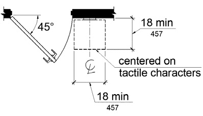
FIGURE 11B-703.4.2
LOCATION OF TACTILE SIGNS AT DOORS

11B-703.5 Visual characters. Visual characters shall comply with Section 11B-703.5.
Exception: Where visual characters comply with Section 11B-703.2 _|Signs; Raised Characters|_ and are accompanied by Braille complying with Section 11B-703.3, they shall not be required to comply with Sections 11B-703.5.2 through 11B-703.5.6, 11B-703.5.8 _|Stroke Thickness|_ and 11B-703.5.9 _|Line Spacing|_.
[2010 ADAS] EXCEPTION: Where visual characters comply with 703.2 and are accompanied by braille complying with 703.3, they shall not be required to comply with 703.5.2 through 703.5.9.
11B-703.5.1 Finish and contrast. Characters and their background shall have a non-glare finish. Characters shall contrast with their background with either light characters on a dark background or dark characters on a light background.
11B-703.5.2 Case. Characters shall be uppercase or lowercase or a combination of both.
11B-703.5.3 Style. Characters shall be conventional in form. Characters shall not be italic, oblique, script, highly decorative, or of other unusual forms.
11B-703.5.4 Character proportions. Characters shall be selected from fonts where the width of the uppercase letter “O” is 60 percent minimum and 110 percent maximum of the height of the uppercase letter “I”.
[2010 ADAS] 703.5.4 Character Proportions. Characters shall be selected from fonts where the width of the uppercase letter "O" is 55 percent minimum and 110 percent maximum of the height of the uppercase letter "I".
11B-703.5.5 Character height. Minimum character height shall comply with Table 11B-703.5.5. Viewing distance shall be measured as the horizontal distance between the character and an obstruction preventing further approach towards the sign. Character height shall be based on the uppercase letter “I”.
Exception: Where provided, floor plans providing emergency procedures information in accordance with Title 19 shall not be required to comply with Section 11B-703.5.5.
TABLE 11B-703.5.5
VISUAL CHARACTER HEIGHT
| Height To Finish Floor Or Ground From Baseline Of Character | Horizontal Viewing Distance | Minimum Character Height |
| 40 inches (1016 mm) to less than or equal to 70 inches (1778 mm) | less than 72 inches (1829 mm) | 5/8 inch (15.9 mm) |
| 72 inches (1829 mm) and greater | 5/8 inch (15.9 mm), plus 1/8 inch (3.2 mm) per foot (305 mm) of viewing distance above 72 inches (1829 mm) | |
| Greater than 70 inches (1778 mm) to less than or equal to 120 inches (3048 mm) | less than 180 inches (4572 mm) | 2 inches (51 mm) |
| 180 inches (4572 mm) and greater | 2 inches (51 mm) , plus 1/8 inch (3.2 mm) per foot (305 mm) of viewing distance above 180 inches (4572 mm) | |
| Greater than 120 inches (3048 mm) | less than 21 feet (6401 mm) | 3 inches (76 mm) |
| 21 feet (6401 mm) and greater | 3 inches (76 mm) , plus 1/8 inch (3.2 mm) per foot (305 mm) of viewing distance above 21 feet (6401 mm) |
11B-703.5.6 Height from finish floor or ground. Visual characters shall be 40 inches (1016 mm) minimum above the finish floor or ground.
Exceptions:
1. Visual characters indicating elevator car controls shall not be required to comply with Section 11B-703.5.6.
2. Floor-level exit signs complying with Chapter 10, Section 1013.7 shall not be required to comply with Section 11B-703.5.6.
3. Where provided, floor plans providing emergency procedures information in accordance with Title 19 shall not be required to comply with Section 11B-703.5.6
11B-703.5.7 Stroke thickness. Stroke thickness of the uppercase letter “I” shall be 10 percent minimum and 20 percent maximum of the height of the character.
[2010 ADAS] 703.5.7 Stroke Thickness. Stroke thickness of the uppercase letter "I" shall be 10 percent minimum and 30 percent maximum of the height of the character.
11B-703.5.8 Character spacing. Character spacing shall be measured between the two closest points of adjacent characters, excluding word spaces. Spacing between individual characters shall be 10 percent minimum and 35 percent maximum of character height.
11B-703.5.9 Line spacing. Spacing between the baselines of separate lines of characters within a message shall be 135 percent minimum and 170 percent maximum of the character height.
11B-703.5.10 Format. Text shall be in a horizontal format.
11B-703.6 Pictograms. Pictograms shall comply with Section 11B-703.6.

11B-703.6.1 Pictogram field. Pictograms shall have a field height of 6 inches (152 mm) minimum. Characters and Braille shall not be located in the pictogram field.

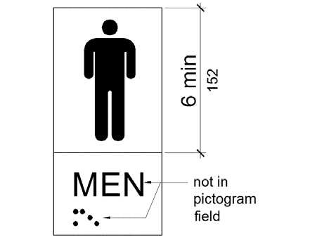
FIGURE 11B-703.6.1
PICTOGRAM FIELD
11B-703.6.2 Finish and contrast. Pictograms and their field shall have a non-glare finish. Pictograms shall contrast with their field with either a light pictogram on a dark field or a dark pictogram on a light field.
11B-703.6.3 Text descriptors. Pictograms shall have text descriptors located directly below the pictogram field. Text descriptors shall comply with Sections 11B-703.2 _|Signs; Raised Characters|_, 11B-703.3 _|Braille|_ and 11B-703.4 _|Installation Height and Location|_.
11B-703.7 Symbols of accessibility. Symbols of accessibility shall comply with Section 11B-703.7.

11B-703.7.1 Finish and contrast. Symbols of accessibility and their background shall have a non-glare finish. Symbols of accessibility shall contrast with their background with either a light symbol on a dark background or a dark symbol on a light background.
11B-703.7.2 Symbols
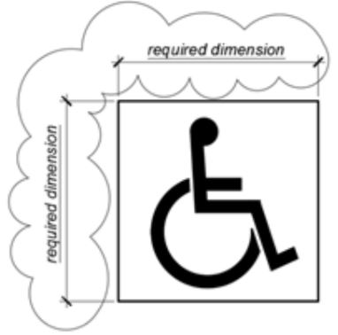
11B-703.7.2.1 International Symbol of Accessibility.
The International Symbol of Accessibility shall comply with Figure 11B-703.7.2.1. The symbol shall consist of a white figure on a blue background. The color blue shall approximate FS 15090 in Federal Standard 595C. A border may be provided inside or outside of the minimum required International Symbol of Accessibility dimension.
[2010 ADAS] 703.7.2.1 International Symbol of Accessibility. The International Symbol of Accessibility shall comply with Figure 703.7.2.1.
Exceptions:
1. The appropriate enforcement agency may approve other colors provided the symbol contrast is light on dark or dark on light.
2. On the accessibility function button on hall call consoles in a destination-oriented elevator system the International Symbol of Accessibility shall be a white symbol on a black background.
Figure 11B-703.7.2.1 International Symbol of Accessibility

11B-703.7.2.2 International Symbol of TTY. The International Symbol of TTY shall comply with Figure 11B-703.7.2.2.

FIGURE 11B-703.7.2.2
INTERNATIONAL SYMBOL OF TTY
11B-703.7.2.3 Volume control telephones. Telephones with a volume control shall be identified by a pictogram of a telephone handset with radiating sound waves on a square field such as shown in Figure 11B-703.7.2.3.
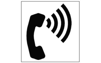
FIGURE 11B-703.7.2.3
VOLUME CONTROL TELEPHONE
11B-703.7.2.4 Assistive listening systems. Assistive listening systems shall be identified by the International Symbol of Access for Hearing Loss complying with Figure 11B-703.7.2.4.

FIGURE 11B-703.7.2.4
INTERNATIONAL SYMBOL OF ACCESS FOR HEARING LOSS
11B-703.7.2.6 Toilet and bathing facilities geometric symbols. Geometric symbols at entrances to toilet and bathing rooms shall be mounted at 58 inches (1473 mm) minimum and 60 inches (1524 mm) maximum above the finish floor or ground surface measured from the centerline of the symbol. Where a door is provided the symbol shall be mounted within 1 inch (25 mm) of the vertical centerline of the door.

When toilet and bathing facilities have doorway openings instead of doors, such as at airports or stadiums, the geometric identification symbol should be located at the proper height adjacent to the opening or incorporated into the required tactile identification sign. For example, the geometric symbol may be used as the sign background with raised characters and Braille per Sections 11B-703.2 and 11B-703.3.◼
11B-703.7.2.6.1 Men’s toilet and bathing facilities.
A triangle symbol shall be located at entrances to men’s toilet and bathing facilities. The triangle symbol shall be an equilateral triangle 1/4 inch (6.4 mm) thick with edges 12 inches (305 mm) long and a vertex pointing upward. The color of the triangle symbol shall contrast with the color of the door or surface on which the triangle symbol is mounted, either light on a dark background or dark on a light background.
Exception: Within secure perimeter of detention and correctional facilities, geometric symbols shall not be required to be ¼ inch (6.4 mm) thick.
11B-703.7.2.6.2 Women’s toilet and bathing facilities.
A circle symbol shall be located at entrances to woman’s toilet and bathing facilities. The circle symbol shall be ¼ inch (6.4 mm) thick and 12 inches (305 mm) in diameter. The color of the circle symbol shall contrast with the color of the door or surface on which the circle symbol is mounted, either light on a dark background or dark on a light background.
Exception: Within secure perimeter of detention and correctional facilities, geometric symbols shall not be required to be ¼ inch (6.4 mm) thick.
11B-703.7.2.6.3 Unisex toilet and bathing facilities.
A combined circle and triangle symbol shall be located at entrances to unisex toilet and bathing facilities. The combined circle and triangle symbol shall consist of a circle symbol 1/4 inch (6.4 mm) thick and 12 inches (305 mm) in diameter with a 1/4 inch (6.4 mm) thick equilateral triangle symbol superimposed on and geometrically inscribed within the 12-inch (305 mm) diameter of the circle symbol. The vertices of the triangle symbol shall be located 1/4 inch (6.4 mm) maximum from the edge of the circle symbol with a vertex pointing upward. The color of the triangle symbol shall contrast with the color of the circle symbol, either light on a dark background or dark on a light background. The color of the circle symbol shall contrast with the color of the door or surface on which the combined circle and triangle symbol is mounted, either light on a dark background or dark on a light background.
Exception: Within secure perimeter of detention and correctional facilities, geometric symbols shall not be required to be ¼ inch (6.4 mm) thick.
11B-703.7.2.6.4 Edges and vertices on geometric symbols. Edges shall be eased or rounded at 1/16 inch (1.59 mm) minimum, or chamfered at 1/8 inch (3.2 mm) maximum. Vertices shall be radiused between 1/8 inch (3.2 mm) minimum and ¼ inch (6.4 mm) maximum.
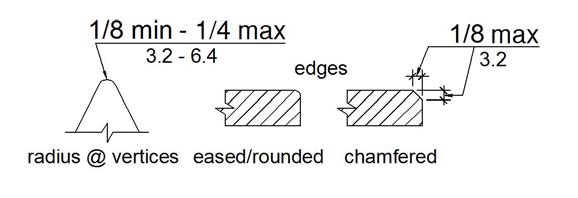
FIGURE 11B-703.7.2.6.4
EDGES AND VERTICES ON GEOMETRIC SYMBOLS
11B-703.7.2.7 Pedestrian traffic-control buttons. Pole-supported pedestrian traffic control buttons shall be identified with color coding consisting of a textured horizontal yellow band 2 inches (51 mm) in width encircling the pole, and a 1-inch-wide (25 mm) dark border band above and below this yellow band. Color coding shall be placed immediately above the control button. Control buttons shall be located no higher than 48 inches (1219 mm) above the ground surface adjacent to the pole.
11B-703.8 Variable message signs.
11B-703.8.1 General. High resolution variable message sign (VMS) characters shall comply with Sections 11B-703.5 and 11B-703.8.12 through 11B-703.8.14. Low resolution variable message sign (VMS) characters shall comply with 11B-703.8.
11B-703.8.2 Case. Low resolution VMS characters shall be uppercase.
11B-703.8.3 Style. Low resolution VMS characters shall be conventional in form, shall be san serif, and shall not be italic, oblique, script, highly decorative, or of other unusual forms.
11B-703.8.4 Character height. The uppercase letter “I” shall be used to determine the allowable height of all low resolution VMS characters of a font. Viewing distance shall be measured as the horizontal distance between the character and an obstruction preventing further approach towards the sign. The uppercase letter “I” of the font shall have a minimum height complying with Table 11B-703.8.4.
Exception: In assembly seating where the maximum viewing distance is 100 feet (30.5 m) or greater, the height of the uppercase “I” of low resolution VMS fonts shall be permitted to be 1 inch (25 mm) for every 30 feet (9144 mm) of viewing distance, provided the character height is 8 inches (203 mm) minimum. Viewing distance shall be measured as the horizontal distance between the character and where someone is expected to view the sign.
TABLE 11B-703.8.4 LOW RESOLUTION VMS CHARACTER HEIGHT
| HEIGHT ABOVE FLOOR TO BASELINE OF CHARACTER | HORIZONTAL VIEWING DISTANCE | MINIMUM CHARACTER HEIGHT |
| 40 inches (1016 mm) to less than or equal to 70 inches (1778 mm) | Less than 10 feet (3048 mm) | 2 inches (51 mm) |
| 10 feet (3048 mm) and greater | 2 inches (51 mm), plus 1/5 inch (5.1 mm) per foot (305 mm) of viewing distance above 10 feet (3048 mm) | |
| Greater than 70 inches (1778 mm) to less than or equal to 120 inches (3048 mm) | Less than 15 feet (4572 mm) | 3 inches (76 mm) |
| 15 feet (4572 mm) and greater | 3 inches (76 mm), plus 1/5 inch (5.1 mm) per foot (305 mm) of viewing distance above 15 feet (4572 mm) | |
| Greater than 120 inches (3048 mm) | Less than 20 feet (6096 mm) | 4 inches (102 mm) |
| 20 feet (6096 mm) and greater | 4 inches (102 mm), plus 1/5 inch (5.1 mm) per foot (305 mm) of viewing distance above 20 feet (6096 mm) |
11B-703.8.5 Character width. The uppercase letter “O” shall be used to determine the allowable width of all low resolution VMS characters of a font. Low resolution VMS characters shall comply with the pixel count for character width in Table 11B-703.8.5.
TABLE 11B-703.8.5 PIXEL COUNT FOR LOW RESOLUTION VMS
| CHARACTER HEIGHT | CHARACTER WIDTH RANGE | STROKE WIDTH RANGE | CHARACTER SPACING RANGE |
| 7 | 5-6 | 1 | 2 |
| 8 | 6-7 | 1-2 | 2-3 |
| 9 | 6-8 | 1-2 | 2-3 |
| 10 | 7-9 | 2 | 2-4 |
| 11 | 8-10 | 2 | 2-4 |
| 12 | 8-11 | 2 | 3-4 |
| 13 | 9-12 | 2-3 | 3-5 |
| 14 | 10-13 | 2-3 | 3-5 |
| 15 | 11-14 | 2-3 | 3-5 |
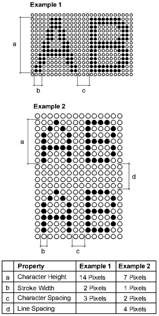
FIGURE 11B-703.8.5
LOW RESOLUTION VMS CHARACTERS
11B-703.8.6 Stroke width. The uppercase letter “I” shall be used to determine the allowable stroke width of all low resolution VMS characters of a font. Low resolution VMS characters shall comply with the pixel count for stroke width in Table 11B-703.8.5.
11B-703.8.7 Character spacing. Spacing shall be measured between the two closest points of adjacent low resolution VMS characters within a message, excluding word spaces. Low resolution VMS character spacing shall comply with the pixel count for character spacing in Table 11B-703.8.5.
11B-703.8.8 Line spacing. Low resolution VMS characters shall comply with Section 11B-703.5.9.
11B-703.8.9 Height above floor. Low resolution VMS characters shall be 40 inches (1016 mm) minimum above the floor of the viewing position, measured to the baseline of the character. Heights of low resolution variable message sign characters shall comply with Table 11B-703.8.4, based on the size of the characters on the sign.
11B-703.8.10 Finish. The background of low resolution VMS characters shall have a non-glare finish.
11B-703.8.11 Contrast. Low resolution VMS characters shall be light characters on a dark background.
11B-703.8.12 Protective covering. Where a protective layer is placed over VMS characters through which the VMS characters must be viewed, the protective covering shall have a non-glare finish.
11B-703.8.13 Brightness. The brightness of variable message signs in exterior locations shall automatically adjust in response to change in ambient light levels.
11B-703.8.14 Rate of change. Where a VMS message can be displayed in its entirety on a single screen, it shall be displayed on a single screen and shall remain motionless on the screen for a minimum 3 seconds or one second minimum for every 7 characters of the message including spaces, whichever is longer.
11B-704 Telephones.
11B-704.1 General. Public telephones shall comply with Section 11B-704.
11B-704.2 Wheelchair accessible telephones. Wheelchair accessible telephones shall comply with Section 11B-704.2.
11B-704.2.1 Clear floor or ground space. A clear floor or ground space complying with Section 11B-305 shall be provided. The clear floor or ground space shall not be obstructed by bases, enclosures, or seats.
11B-704.2.1.1 Parallel approach. Where a parallel approach is provided, the distance from the edge of the telephone enclosure to the face of the telephone unit shall be 10 inches (254 mm) maximum.
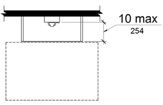
FIGURE 11B-704.2.1.1
PARALLEL APPROACH TO TELEPHONE
11B-704.2.1.2 Forward approach. Where a forward approach is provided at a telephone within an enclosure, the counter may extend beyond the face of the telephone 20 inches (508 mm) into the required clear floor or ground space and the enclosure may extend beyond the face of the telephone 24 inches (610 mm). If an additional 6 inches (152 mm) in width of clear floor space is provided, creating a clear floor space of 36 inches by 48 inches (914 mm by 1219 mm), the enclosure may extend more than 24 inches (610 mm) beyond the face of the telephone.
[2010 ADAS] 704.2.1.2 Forward Approach. Where a forward approach is provided, the distance from the front edge of a counter within the telephone enclosure to the face of the telephone unit shall be 20 inches (510 mm) maximum.
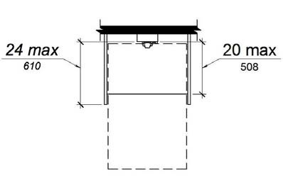
FIGURE 11B-704.2.1.2 ‡‡
FORWARD APPROACH TO TELEPHONE
11B-704.2.2 Operable parts. Operable parts shall comply with Section 11B-309. Telephones shall have push-button controls where such service is available.
11B-704.2.3 Telephone directories. Telephone directories, where provided, shall be located in accordance with Section 11B-309.
11B-704.2.4 Cord length. The cord from the telephone to the handset shall be 29 inches (737 mm) long minimum.
11B-704.3 Volume control telephones. Public telephones required to have volume controls shall be equipped with a receive volume control that provides a gain adjustable up to 20 dB minimum. For incremental volume control, provide at least one intermediate step of 12 dB of gain minimum. An automatic reset shall be provided. Volume control telephones shall be equipped with a receiver that generates a magnetic field in the area of the receiver cap. Public telephones with volume control shall be hearing aid compatible.
[2010 ADAS] 704.3 Volume Control Telephones. Public telephones required to have volume controls shall be equipped with a receive volume control that provides a gain adjustable up to 20 dB minimum. For incremental volume control, provide at least one intermediate step of 12 dB of gain minimum. An automatic reset shall be provided.
11B-704.4 TTYs. TTYs provided at a public pay telephone shall be permanently affixed within, or adjacent to, the telephone enclosure. Where an acoustic coupler is used, the telephone cord shall be sufficiently long to allow connection of the TTY and the telephone receiver.
[2010 ADAS] 704.4 TTYs. TTYs required at a public pay telephone shall be permanently affixed within, or adjacent to, the telephone enclosure. Where an acoustic coupler is used, the telephone cord shall be sufficiently long to allow connection of the TTY and the telephone receiver.
11B-704.4.1 Height. When in use, the touch surface of TTY keypads shall be 34 inches (864 mm) minimum above the finish floor.
Exception: Where seats are provided, TTYs shall not be required to comply with Section 11B-704.4.1.
11B-704.5 TTY shelf. Public pay telephones required to accommodate portable TTYs shall be equipped with a shelf and an electrical outlet within or adjacent to the telephone enclosure. The telephone handset shall be capable of being placed flush on the surface of the shelf. The shelf shall be capable of accommodating a TTY and shall have 6 inches (152 mm) minimum vertical clearance above the area where the TTY is to be placed.
11B-705 Detectable warnings and detectable directional texture.
[2010 ADAS] 705 Detectable Warnings
11B-705.1 Detectable warnings
11B-705.1.1 General. Detectable warnings shall consist of a surface of truncated domes and shall comply with Section 11B-705.
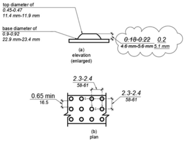
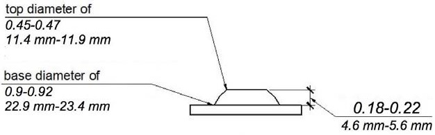
11B-705.1.1.1 Dome size. Truncated domes in a detectable warning surface shall have a base diameter of 0.9 inch (22.9 mm) minimum and 0.92 inch (23.4 mm) maximum, a top diameter of 0.45 inch (11.4 mm) minimum and 0.47 inch (11.9 mm) maximum, and a height of 0.2 inch (5.1 mm).
Figure 11B-705.1 Size and Spacing of Truncated Domes
[2010 ADAS] 705.1.1 Dome Size. Truncated domes in a detectable warning surface shall have a base diameter of 0.9 inch (23 mm) minimum and 1.4 inches (36 mm) maximum, a top diameter of 50 percent of the base diameter minimum to 65 percent of the base diameter maximum, and a height of 0.2 inch (5.1 mm).
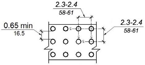
11B-705.1.1.2 Dome spacing. Truncated domes in a detectable warning surface shall have a center-to-center spacing of 2.3 inches (58 mm) minimum and 2.4 inches (61 mm) maximum, and a base-to-base spacing of 0.65 inch (16.5 mm) minimum, measured between the most adjacent domes on a square grid.
[2010 ADAS] 705.1.2 Dome Spacing. Truncated domes in a detectable warning surface shall have a center-to-center spacing of 1.6 inches (41 mm) minimum and 2.4 inches (61 mm) maximum, and a base-to-base spacing of 0.65 inch (17 mm) minimum, measured between the most adjacent domes on a square grid.
Exception: Where installed in a radial pattern, truncated domes shall have a center-to-center spacing of 1.6 inches (41 mm) minimum to 2.4 inches (61 mm) maximum.
(a)
elevation
(enlarged)
(b) FIGURE 11B-705.1 ‡‡
plan
SIZE AND SPACING OF TRUNCATED DOMES
ETA Editor's Note
This Figure has not been updated to reflect the text at 11B-705.1.1.1 regarding dome height. DSA-AC's Advisory Manual still has this same Figure.
11B-705.1.1.3 Color and Contrast. Detectable warning surfaces at transit boarding platform edges, bus stops, hazardous vehicular areas, reflecting pools, and track crossings shall comply with Section 11B-705.1.1.3.1. Detectable warnings at other locations shall comply with either Section 11B-705.1.1.3.1 or Section 11B-705.1.1.3.2. The material used to provide visual contrast shall be an integral part of the surface.
11B-705.1.1.3.1 Detectable warning surfaces shall be yellow and approximate FS 33538 of Federal Standard 595C.
11B-705.1.1.3.2 Detectable warning surfaces shall provide a 70 percent minimum visual contrast with adjacent walking surfaces. Contrast in percent shall be determined by:
Contrast percent = [(B1-B2)/B1] x 100 percent where
B1 = light reflectance value (LRV) of the lighter area and
B2 = light reflectance value (LRV) of the darker area.
[2010 ADAS] 705.1.3 Contrast. Detectable warning surfaces shall contrast visually with adjacent walking surfaces either light-on-dark, or dark-on-light.
Exception: Where the detectable warning surface does not provide a 70 percent minimum contrast with adjacent walking surfaces, a 1 inch (25 mm) wide minimum visually contrasting surface shall separate the detectable warning from adjacent walking surfaces. The visually contrasting surface shall contrast with both the detectable warning and adjacent walking surfaces either light-on-dark, or dark-on-light.
11B-705.1.1.4 Resiliency. Detectable warning surfaces shall differ from adjoining surfaces in resiliency or sound-on-cane contact.
Exception: Detectable warning surfaces at curb ramps, islands or cut-through medians shall not be required to comply with Section 11B-705.1.1.4.
11B-705.1.2 Locations. Detectable warnings at the following locations shall comply with Section 11B-705.1.
11B-705.1.2.1 Platform edges. Detectable warning surfaces at platform boarding edges shall be 24 inches (610 mm) wide and shall extend the full length of the public use areas of the platform.
11B-705.1.2.2 Curb ramps. Detectable warnings at curb ramps shall extend 36 inches (914 mm) in the direction of travel. Detectable warnings shall extend the full width of the ramp run less 2 inches (51 mm) maximum on each side, excluding any flared sides. Detectable warnings shall be located so the edge nearest the curb is 6 inches (152 mm) minimum and 8 inches (203 mm) maximum from the line at the face of the curb marking the transition between the curb and the gutter, street or highway.
Exception: On parallel curb ramps, detectable warnings shall be placed on the turning space at the flush transition between the street and sidewalk. Detectable warnings shall extend the full width of the turning space at the flush transition between the street and the sidewalk less 2 inches (51 mm) maximum on each side.
11B-705.1.2.3 Islands or cut-through medians. Detectable warnings at pedestrian islands or cut-through medians shall be 36 inches (914 mm) minimum in depth extending the full width of the pedestrian path or cut-through less 2 inches (51 mm) maximum on each side, placed at the edges of the pedestrian island or cut-through median, and shall be separated by 24 inches (610 mm) minimum of walking surface without detectable warnings.
Exception: Detectable warnings shall be 24 inches (610 mm) minimum in depth at pedestrian islands or cut-through medians that are less than 96 inches (2438 mm) in length in the direction of pedestrian travel.
11B-705.1.2.4 Bus stops. When detectable warnings are provided at bus stop boarding and alighting areas, the detectable warnings shall extend the full width of the boarding/alighting area and shall be 36 inches (914 mm) minimum in depth.
11B-705.1.2.5 Hazardous vehicular areas. Detectable warnings at hazardous vehicular areas shall be 36 inches (914 mm) in width.
11B-705.1.2.6 Reflecting pools. When detectable warnings are provided at reflecting pools, it shall be 24 inches (610 mm) minimum and 36 inches (914 mm) maximum in width.
11B-705.1.2.7 Track crossings. Detectable warnings at track crossings shall be 36 inches (914 mm) in the direction of pedestrian travel and extend the full width of the circulation path.
11B-705.2 Detectable directional texture. Detectable directional texture at transit boarding platforms shall comply with Figure 11B-705.2 and shall be 0.1 inch (2.5 mm) in height that tapers off to 0.04 inch (1.0 mm) , with bars raised 0.2 inch (5.1 mm) from the surface. The raised bars shall be 1.3 inches (33 mm) wide and 3 inches (76 mm) from center-to-center of each bar. This surface shall differ from adjoining walking surfaces in resiliency or sound-on-cane contact. The color shall be yellow and approximate FS 33538 of Federal Standard 595C. This surface will be placed directly behind the yellow detectable warning texture specified in Section 11B-705.1.2.1, aligning with all doors of the transit vehicles where passengers will embark. The width of the directional texture shall be equal to the width of the transit vehicle’s door opening. The depth of the texture shall not be less than 36 inches (914 mm).
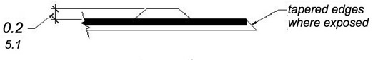
(a)
elevation
(enlarged)
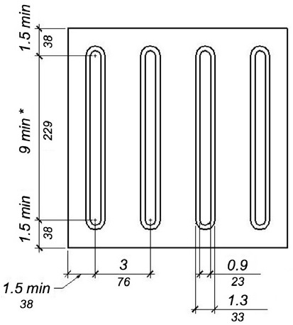
*industry standard for overall bar length is 11 1/4 - 11 1/2 (286 mm-292 mm)
(b)
plan
FIGURE 11B-705.2 ‡‡
DETECTABLE DIRECTIONAL TEXTURE
11B-705.3 Product Approval. Only approved DSA-AC detectable warning products and directional surfaces shall be installed as provided in the California Code of Regulations (CCR), Title 24, Part 1, Chapter 5, Articles 2, 3 and 4. Refer to CCR Title 24, Part 12, Chapter 11B, Section 12-11B.205 for building and facility access specifications for product approval for detectable warning products and directional surfaces.
11B-706 Assistive listening systems.
11B-706.1 General. Assistive listening systems required in assembly areas, conference and meeting rooms shall comply with Section 11B-706.
[2010 ADAS] 706.1 General. Assistive listening systems required in assembly areas shall comply with 706.
[2010 ADAS] Advisory 706.1 General. Assistive listening systems are generally categorized by their mode of transmission. There are hard-wired systems and three types of wireless systems: induction loop, infrared, and FM radio transmission. Each has different advantages and disadvantages that can help determine which system is best for a given application. For example, an FM system may be better than an infrared system in some open-air assemblies since infrared signals are less effective in sunlight. On the other hand, an infrared system is typically a better choice than an FM system where confidential transmission is important because it will be contained within a given space.
The technical standards for assistive listening systems describe minimum performance levels for volume, interference, and distortion. Sound pressure levels (SPL), expressed in decibels, measure output sound volume. Signal-to-noise ratio (SNR or S/N), also expressed in decibels, represents the relationship between the loudness of a desired sound (the signal) and the background noise in a space or piece of equipment. The higher the SNR, the more intelligible the signal. The peak clipping level limits the distortion in signal output produced when high-volume sound waves are manipulated to serve assistive listening devices.
Selecting or specifying an effective assistive listening system for a large or complex venue requires assistance from a professional sound engineer. The Access Board has published technical assistance on assistive listening devices and systems: http://www.Access-Board.gov/Research/Completed-Research/Large-Area-Assistive-Listening-Systems.
11B-706.2 Receiver jacks. Receivers required for use with an assistive listening system shall include a 1/8 inch (3.2 mm) standard mono jack.
11B-706.3 Receiver hearing-aid compatibility. Receivers required to be hearing-aid compatible shall interface with telecoils in hearing aids through the provision of neckloops.
11B-706.4 Sound pressure level. Assistive listening systems shall be capable of providing a sound pressure level of 110 dB minimum and 118 dB maximum with a dynamic range on the volume control of 50 dB.
11B-706.5 Signal-to-noise ratio. The signal-to-noise ratio for internally generated noise in assistive listening systems shall be 18 dB minimum.
11B-706.6 Peak clipping level. Peak clipping shall not exceed 18 dB of clipping relative to the peaks of speech.
11B-707 Automatic teller machines, fare machines and point-of-sale devices.
[2010 ADAS] 707 Automatic Teller Machines and Fare Machines
11B-707.1 General. Automatic teller machines, fare machines and point-of-sale devices shall comply with Section 11B-707.
[2010 ADAS] 707.1 General. Automatic teller machines and fare machines shall comply with 707.
11B-707.2 Clear floor or ground space. A clear floor or ground space complying with Section 11B-305 shall be provided.
Exception: Clear floor or ground space shall not be required at drive-up only automatic teller machines and fare machines.
11B-707.3 Operable parts. Operable parts shall comply with Section 11B-309. Unless a clear or correct key is provided, each operable part shall be able to be differentiated by sound or touch, without activation.
Exceptions:
1. Drive-up only automatic teller machines and fare machines shall not be required to comply with Sections 11B-309.2 and 11B-309.3.
2. Where automatic teller machines and fare machines do not require compliance with 11B-707.2, compliance with 11B-309.2 and 11B-309.3 shall not be required.
3. Where point-of-sale devices do not require compliance with Section 11B-707.2, compliance with Sections 11B-309.2 and 11B-309.3 shall not be required.
11B-707.4 Privacy. Automatic teller machines shall provide the opportunity for the same degree of privacy of input and output available to all individuals.
ETA Editor's Note
The Department of Justice considers the communication-related elements of ATMs to be auxiliary aids and services, rather than structural elements, to which the Safe Harbor allowance for elements built in compliance with the 1991 Standards does not apply. The Department believes that the limitations on the effective communication requirements, i.e., a covered entity does not have to take measures that would result in a fundamental alteration of its program or would cause undue burdens, provide adequate protection to operators of ATMs. [From Part 36 Nondiscrimination on the Basis of Disability in Public Accommodations and Commercial Facilities (as amended by the final rule published on September 15, 2010)].
11B-707.5 Speech output. Machines shall be speech enabled. Operating instructions and orientation, visible transaction prompts, user input verification, error messages, and all displayed information for full use shall be accessible to and independently usable by individuals with vision impairments. Speech shall be delivered through a mechanism that is readily available to all users, including but not limited to, an industry standard connector or a telephone handset. Speech shall be recorded or digitized human, or synthesized.
Exceptions:
1. Audible tones shall be permitted instead of speech for visible output that is not displayed for security purposes, including but not limited to, asterisks representing personal identification numbers.
2. Advertisements and other similar information shall not be required to be audible unless they convey information that can be used in the transaction being conducted.
3. Where speech synthesis cannot be supported, dynamic alphabetic output shall not be required to be audible.
11B-707.5.1 User control. Speech shall be capable of being repeated or interrupted. Volume control shall be provided for the speech function.
Exception: Speech output for any single function shall be permitted to be automatically interrupted when a transaction is selected.
11B-707.5.2 Receipts.
Where receipts are provided, speech output devices shall provide audible balance inquiry information, error messages, and all other information on the printed receipt necessary to complete or verify the transaction.
Exceptions:
1. Machine location, date and time of transaction, customer account number, and the machine identifier shall not be required to be audible.
2. Information on printed receipts that duplicates information available on-screen shall not be required to be presented in the form of an audible receipt.
3. Printed copies of bank statements and checks shall not be required to be audible.
11B-707.6 Input. Input devices shall comply with Section 11B-707.6.
11B-707.6.1 Input controls. At least one tactilely discernible input control shall be provided for each function. Where provided, key surfaces not on active areas of display screens, shall be raised above surrounding surfaces. Where membrane keys are the only method of input, each shall be tactilely discernible from surrounding surfaces and adjacent keys.
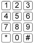
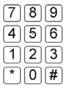
11B-707.6.2 Numeric keys. Numeric keys shall be arranged in a 12-key ascending or descending telephone keypad layout. The number five key shall be tactilely distinct from the other keys.
(a)
12-key
ascending
(b)
12-key
descending
FIGURE 11B-707.6.2
NUMERIC KEY LAYOUT
11B-707.6.3 Function keys. Function keys shall comply with Section 11B-707.6.3.
11B-707.6.3.1 Contrast. Function keys shall contrast visually from background surfaces. Characters and symbols on key surfaces shall contrast visually from key surfaces. Visual contrast shall be either light-on-dark or dark-on-light.
Exception: Tactile symbols required by Section 11B-707.6.3.2 shall not be required to comply with Section 11B-707.6.3.1.
11B-707.6.3.2 Tactile symbols. Function key surfaces shall have tactile symbols as follows: Enter or Proceed key: raised circle; Clear or Correct key: raised left arrow; Cancel key: raised letter ex; Add Value key: raised plus sign; Decrease Value key: raised minus sign.
11B-707.7 Display screen. The display screen shall comply with Section 11B-707.7.
Exception: Drive-up only automatic teller machines and fare machines shall not be required to comply with Section 11B-707.7.1.
11B-707.7.1 Visibility. The display screen shall be visible from a point located 40 inches (1016 mm) above the center of the clear floor space in front of the machine.
11B.707.7.1.1 Vertically mounted display screen. Where display screens are mounted vertically or tipped away from the viewer less than 30 degrees, the center line of the display screen and other display devices shall be no more than 52 inches (1321 mm) above the floor or ground surface.
11B.707.7.1.2 Angle-mounted display screen. Where display screens are mounted tipped away from the viewer 30 degrees to less than 60 degrees from vertical, the center line of the display screen and other display devices shall be no more than 44 inches (1118 mm) above the floor or ground surface.
11B.707.7.1.3 Horizontally mounted display screen. Where display screens are mounted tipped away from the viewer 60 degrees to 90 degrees (horizontal) from vertical, the center line of the display screen and other display devices shall be no more than 34 inches (864 mm) above the floor or ground surface.
11B-707.7.2 Characters. Characters displayed on the screen shall be in a sans serif font. Characters shall be 3/16 inch (4.8 mm) high minimum based on the uppercase letter "I". Characters shall contrast with their background with either light characters on a dark background or dark characters on a light background.
11B-707.8 Braille instructions. Braille instructions for initiating the speech mode shall be provided. Braille shall comply with Section 11B-703.3.
11B-707.9 Point-of-sale devices. Point-of-sale devices shall comply with Section 11B-707.9.
11B-707.9.1 General. Point-of-sale systems that include a video touch screen or any other non-tactile keypad shall be equipped with either of the following:
11B-707.9.1.1 Tactilely discernible numerical keypad. A tactilely discernible numerical keypad similar to a telephone keypad containing a raised dot with a dot base diameter between 1.5 mm and 1.6 mm and a height between 0.6 mm and 0.9 mm on the number 5 key that enables a visually impaired person to enter his or her own personal identification number or any other personal information necessary to process the transaction in a manner that provides the opportunity for the same degree of privacy input and output available to all individuals.
11B-707.9.1.2 Other technology. Other technology, such as a radio frequency identification device, fingerprint biometrics, or some other mechanism that enables a visually impaired person to access the video touch screen device with his or her personal identifier and to process his or her transaction in a manner that provides the opportunity for the same degree of privacy input and output available to all individuals. Where a video screen overlay is provided it shall be equipped with a tactilely discernible numerical keypad complying with Section 11B-707.9.1.1.
11B-708 Two-way communication systems.
11B-708.1 General. Two-way communication systems shall comply with Section 11B-708.
11B-708.2 Audible and visual indicators. The system shall provide both audible and visual signals.
11B-708.3 Handsets. Handset cords, if provided, shall be 29 inches (737 mm) long minimum.
11B-708.4 Residential dwelling unit communication systems. Communications systems between a residential dwelling unit and a site, building, or floor entrance shall comply with Section 11B-708.4.
11B-708.4.1 Common use or public use system interface. The common use or public use system interface shall include the capability of supporting voice and TTY communication with the residential dwelling unit interface.
11B-708.4.2 Residential dwelling unit interface. The residential dwelling unit system interface shall include a telephone jack capable of supporting voice and TTY communication with the common use or public use system interface.
User Comments/Questions
Add Comment/Question