4.13 Doors.
4.13.1 General.
Doors required to be accessible by 4.1 shall comply with the requirements of 4.13.
4.13.2 Revolving Doors and Turnstiles.
Revolving doors or turnstiles shall not be the only means of passage at an accessible entrance or along an accessible route. An accessible gate or door shall be provided adjacent to the turnstile or revolving door and shall be so designed as to facilitate the same use pattern.
4.13.3 Gates.
Gates, including ticket gates, shall meet all applicable specifications of 4.13.
4.13.4 Double-Leaf Doorways.
If doorways have two independently operated door leaves, then at least one leaf shall meet the specifications in 4.13.5 and 4.13.6. That leaf shall be an active leaf.
4.13.5 Clear Width.
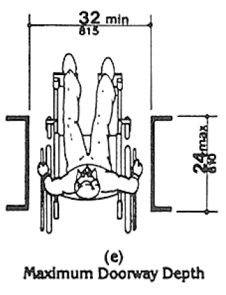
Doorways shall have a minimum clear opening of 32 in (815 mm) with the door open 90 degrees, measured between the face of the door and the opposite stop (see Fig. 24(a), (b), (c), and (d)). Openings more than 24 in (610 mm) in depth shall comply with 4.2.1 and 4.3.3 (see Fig. 24(e)).
EXCEPTION: Doors not requiring full user passage, such as shallow closets, may have the clear opening reduced to 20 in (510 mm) minimum.
Fig. 24 Clear Doorway Width and Depth
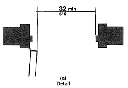
Fig. 24 Clear Doorway Width and Depth
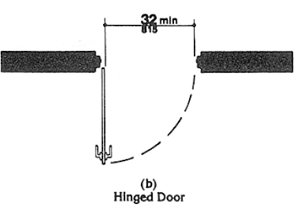
Fig. 24 Clear Doorway Width and Depth
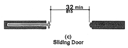
Fig. 24 Clear Doorway Width and Depth
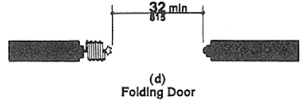
Fig. 24 Clear Doorway Width and Depth
4.13.6 Maneuvering Clearances at Doors.
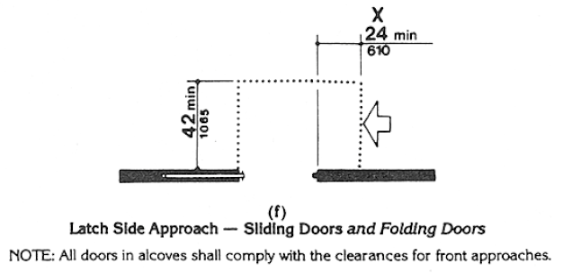
Minimum maneuvering clearances at doors that are not automatic or power-assisted shall be as shown in Fig. 25. The floor or ground area within the required clearances shall be level and clear.
EXCEPTION: Entry doors to acute care hospital bedrooms for in-patients shall be exempted from the requirement for space at the latch side of the door (see dimension “x” in Fig. 25) if the door is at least 44 in (1120 mm) wide.
Fig. 25 Maneuvering Clearances at Doors
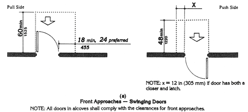
Fig. 25 Maneuvering Clearances at Doors
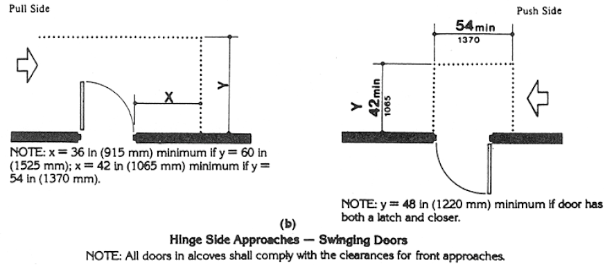
Fig. 25 Maneuvering Clearances at Doors
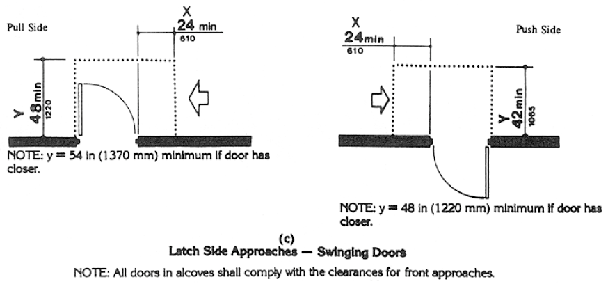
Fig. 25 Maneuvering Clearances at Doors
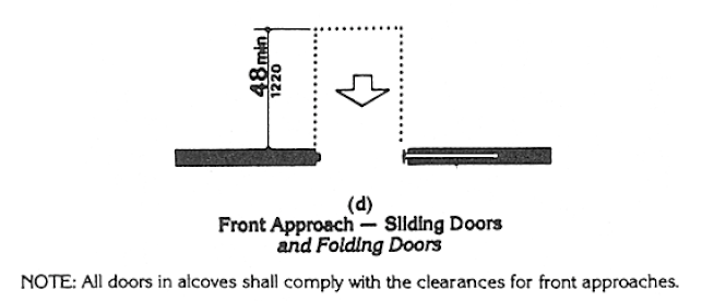
Fig. 25 Maneuvering Clearances at Doors
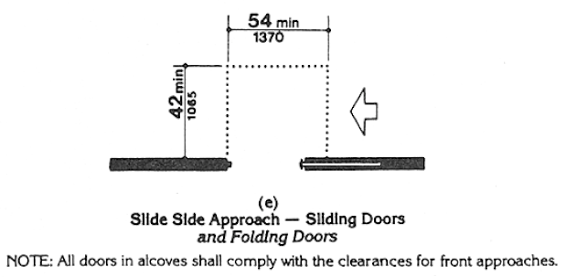
Fig. 25 Maneuvering Clearances at Doors
4.13.7 Two Doors in Series.
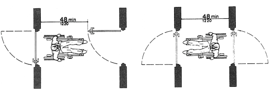
The minimum space between two hinged or pivoted doors in series shall be 48 in (1220 mm) plus the width of any door swinging into the space. Doors in series shall swing either in the same direction or away from the space between the doors (see Fig. 26).
Fig. 26 Two Hinged Doors in Series
4.13.8* Thresholds at Doorways.
Thresholds at doorways shall not exceed 3/4 in (19 mm) in height for exterior sliding doors or 1/2 in (13 mm) for other types of doors. Raised thresholds and floor level changes at accessible doorways shall be beveled with a slope no greater than 1:2 (see 4.5.2).
4.13.9* Door Hardware.
Handles, pulls, latches, locks, and other operating devices on accessible doors shall have a shape that is easy to grasp with one hand and does not require tight grasping, tight pinching, or twisting of the wrist to operate. Lever-operated mechanisms, push-type mechanisms, and U-shaped handles are acceptable designs. When sliding doors are fully open, operating hardware shall be exposed and usable from both sides. Hardware required for accessible door passage shall be mounted no higher than 48 in (1220 mm) above finished floor.
4.13.10* Door Closers.
If a door has a closer, then the sweep period of the closer shall be adjusted so that from an open position of 70 degrees, the door will take at least 3 seconds to move to a point 3 in (75 mm) from the latch, measured to the leading edge of the door.
4.13.11* Door Opening Force.
The maximum force for pushing or pulling open a door shall be as follows:
(1) Fire doors shall have the minimum opening force allowable by the appropriate administrative authority.
(2) Other doors.
(a) exterior hinged doors: (Reserved).
(b) interior hinged doors: 5 lbf (22.2N)
(c) sliding or folding doors: 5 lbf (22.2N)
These forces do not apply to the force required to retract latch bolts or disengage other devices that may hold the door in a closed position.
4.13.12* Automatic Doors and Power-Assisted Doors.
If an automatic door is used, then it shall comply with ANSI/BHMA A156.10‒1985. Slowly opening, low-powered, automatic doors shall comply with ANSI A156.19‒1984. Such doors shall not open to back check faster than 3 seconds and shall require no more than 15 lbf (66.6N) to stop door movement. If a power-assisted door is used, its door-opening force shall comply with 4.13.11 and its closing shall conform to the requirements in ANSI A156.19‒1984.
User Comments/Questions
Add Comment/Question