Independent Wheelchair Transfers in the Built Environment: How Transfer Setup Impacts Performance Phase 2: Final Report
Clear space: A grid 72 inches long by 90 inches wide was used to facilitate the recording of space requirements for each WMD user (Figure 1). This is more space than what is required in the standards. If a person required space beyond the size of the grid, the additional distance was measured and recorded. The grid was positioned such that it was centered with the middle of the transfer station. A coordinate system was assigned to the grid so that each cell was given an alphabetic (y-direction) and numeric (x-direction) name. The center point (0,0) was located on the line in-between the grid values A15 and A16. There were a total of 720, 3 X 3 inch cells in the grid. To calculate the space, three points were recorded for transfers to and from the platform: a point to the right of center, a point to the left of center, and a depth value (Figure 2). These points were found by recording each WMD's outermost points on the grid. When calculating both right of center and left of center values any point right of the reference line (A15/A16) was assigned a positive (+) value, while any point left of the reference line was assigned a negative (-) value. For the depth, all values were positive (+). Space data was recorded as the maximum distance away from the A15/A16 reference line to the right (right of center), the maximum distance away from the A15/A16 reference line to the left (left of center), and the maximum distance away from the front edge of the platform (depth). The angle the WMD was positioned with respect to the transfer station was measured from the front edge of the platform as shown in Figure 2. An angle of 0 degrees was given if the WMD was positioned parallel to the x-direction of the coordinate system (e.g. in parallel with the front edge of the platform). An angle of 90 degrees was given if the WMD was positioned parallel to the y-direction of the coordinate system (e.g. perpendicular to the front edge of the platform).
![Picture of the grid used to measure the location and orientation of set up that was used by study participants when transferring. The grid is made up of three in by three inch squares and is 72 by 90 inches in dimension. The squares are labeled with letters starting with A1 in the top left corner. The numbers increase moving down the column and the letters move from A to X moving across the row, with the zero zero [sic] point marked on the grid between A15 and A16. The grid is divided in half between rows 15 and 16. The coordinate system used to calculate the locations is described. Locations above the midline are marked with a positive x and locations below the midline are negative x. The horizontal axis is marked with a y. The transfer station is next to the grid stationed exactly 24inches from the top and bottom. The station is 42 by 50 inches.](/images/17751)
Figure 1. Scaled version of the 72 inch x 90 inch grid used to record position measurements
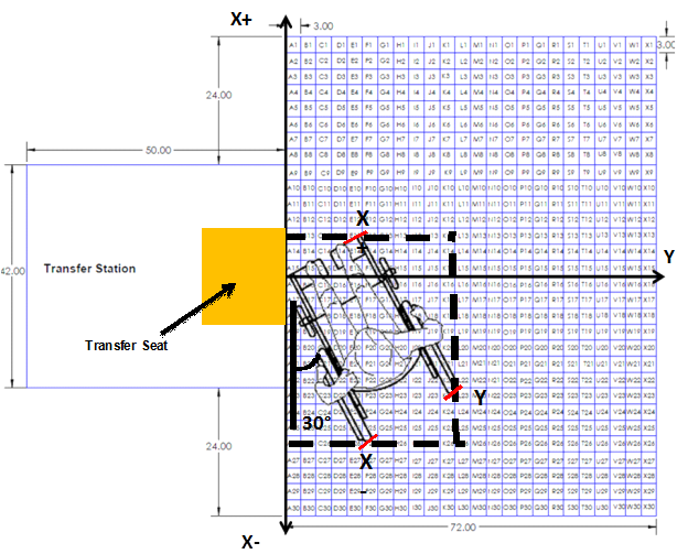
Figure 2. Location of wheelchair and measurement points for clear space calculations. Also shown is the location of the transfer seat on the transfer station. The transfer seat had a fixed depth of 16 inches. The width of the seat was adjustable and could range from a minimum of 18 inches to a maximum of 30 inches. The minimum dimensions of the seat are depicted above.
User Comments/Questions
Add Comment/Question