Synthesis of Literature Relevant to Roundabout Signalization to Provide Pedestrian Access - Final Report
Prepared by:
Vaughan W. Inman
Science Applications International Corporation
and
Gregory W. Davis
Federal Highway Administration, RD&T
6300 Georgetown Pike
McLean, VA 22101
January 11, 2007
OBJECTIVES
The primary objective of this paper is to review the key issues in signalization of roundabouts, where the purpose of the signals is to provide pedestrian access, with particular attention to access for persons with severe vision loss. Although roundabouts are infrequently signalized to provide access to pedestrians, roundabouts crosswalks have been signalized where heavy pedestrian flow would otherwise cause long vehicle delays, where unbalanced traffic volumes require metering to create gaps for entering vehicles, and where signals were needed to accommodate rail transit. This report summarizes topic areas that address issues of signalization of roundabouts to provide pedestrian access. These topic areas include:
-
Pedestrian crosswalk types.
-
Crosswalk location.
-
Traffic signals configurations at roundabout pedestrian crossings.
-
Crossing requirements of blind pedestrians.
-
Accessible pedestrian signals.
-
Pedestrian signal warrants.
-
The effect of traffic signals on roundabout operations.
BACKGROUND
Implementing regulations under Title II of the Americans with Disabilities Act (1) and other statutes require that new construction and alterations are accessible to, and useable by, people with disabilities. In recent years, with the development of guidelines for the public right-of-way, concerns have been raised about the accessibility of roundabouts to persons with severe visual impairments (2) and subsequent research has tended to support those concerns. For instance, Guth, et al. (3) have shown that blind pedestrians require about 3 more seconds than sighted pedestrians to detect naturally occurring gaps in traffic, and that this requirement markedly reduces the number of gaps available to blind pedestrians at roundabouts with moderate to high traffic volume. Nor can blind pedestrians rely on motorists to yield to them. Inman et al. (4) found that at one double lane roundabout, only 14 percent of motorists yielded to blind pedestrians using a long cane or a guide dog. Furthermore, those investigators found that on 10 percent of trials, the blind pedestrians incorrectly identified that both lanes of a double-lane roundabout were blocked by stopped vehicles, when in fact, only one lane was blocked. Geruschat and Hassan (5) reported on a number of factors that can influence motorists’ yielding rate. They found that drivers are more likely to yield at roundabout entrances than exits and when: (1) speeds are lower, (2) the pedestrian is more aggressive, and (3) when the pedestrian has a long cane or guide dog. At a roundabout entrance where measured speeds were about 10 mi/h, almost all drivers yielded to a pedestrian who had one foot into the street and carried a long cane. At a roundabout exit where measured speeds were about 20 mi/h yielding rates to an apparently blind pedestrian were less than 15 percent.
Thus, it appears that many double lane roundabouts are not accessible to pedestrians who are blind. Vehicles are unlikely to yield to these pedestrians, naturally occurring gaps may be rare, and many roundabouts – in particular multilane roundabouts – with pedestrian facilities, do not provide cues that enable pedestrians who rely on traffic sounds to reliably detect gaps that result when vehicles yield to them. For these reasons, draft guidelines developed by the U.S. Access Board (6), would require some form of signalization at new multi-lane roundabout pedestrian crossings.
ROUNDABOUT OVERVIEW
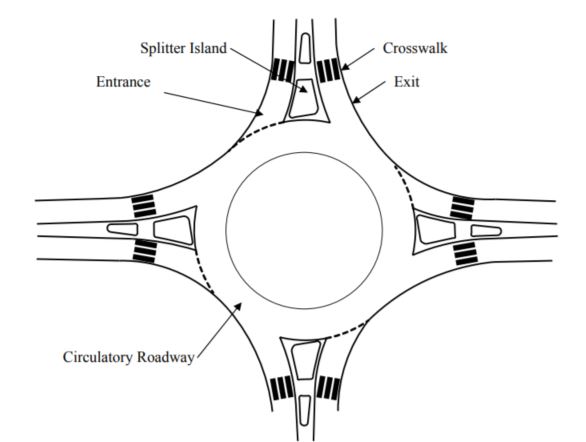
As defined by the Federal Highway Administration (FHWA), modern roundabouts are circular intersections with specific traffic control and design features (7). These features include yield control at entry, channelized approaches, and geometric approach curvature (deflection) to induce entering traffic to slow to the design speed of the circulatory roadway. Figure 1 illustrates the typical locations for crosswalks at roundabouts in the U.S. One end of each crosswalk terminates on a splitter island so that the pedestrian crosses only one direction of traffic at a time. The crosswalks are set back from the intersection to minimize conflicts with turning vehicles.1 Traffic is forced to travel on a curved path, which typically minimizes vehicle speed to between 20 and 30 mi/h.
Figure 1. Illustration of single-lane roundabout with crosswalks
Roundabouts are appearing with increasing frequency in the United States, primarily because of their benefits to traffic operations and safety. Compared to conventional intersections, potential roundabout benefits identified in the FHWA informational guide (7) include: less vehicle delay, fewer crashes, and fewer serious and fatal injuries in crashes, both for vehicle occupants and for pedestrians.
1 It has been pointed out that setting crosswalks back at roundabout is opposite of the policy at traditional intersections where the crosswalks are as close as practicable to the intersection. This apparent contradiction results in part from the fundamental difference between roundabouts and traditional intersections. At roundabouts traffic flow is continuous and there is no pedestrian phase. At traditional traffic device controlled intersections, priority usually alternates between conflicting approaches (i.e., with traffic signal control) or remains with the predominate approach (e.g., with two-way stop control). At roundabouts, placing the crosswalk at the edge of the inscribed circle (juxtaposed to the circular roadway) would expose pedestrians to nearly continuous traffic that approaches from both the side and rear. At the entrance drivers would need to split their attention between possible pedestrians approaching the right and vehicles approaching from the left. Moving the crosswalk back from the circular roadway eliminates the threat to pedestrians from vehicles that approach from the rear and places pedestrians in the drivers’ forward field of vision. At controlled traditional intersections pedestrians can take advantage of the traffic control to obtain a gap, an option not generally available at U.S. roundabouts, and drivers can scan for pedestrians while they are stopped for the control. The right-turn-on-red prohibition when pedestrians are present is intended to eliminate the conflict in which drivers must attend to both pedestrians on their right and approaching vehicles on their left. When roundabouts are signalized, there may be some advantage to moving crosswalks to be proximal to the circular roadway and this is done at fully signalized roundabouts (see Figure 5 for an example in France). However, fully signalized roundabouts are much larger than the “modern roundabouts” currently being built in the U.S., which do not have sufficient space to store vehicles in the circular roadway without stopping traffic flow in all directions and thus eliminating the cost and efficiency benefits that are the hallmark advantages of modern roundabouts.
SIGNALIZATION OF ROUNDABOUTS
United States
Signalization of roundabouts is discouraged in the United States. The Federal Highway Administration’s roundabout informational guide (7) states “roundabouts should never be planned for metering or signalization.” However, the guide does concede that “unexpected demand” may require signalization after a roundabout is constructed. The FHWA guide goes on to describe three signalization alternatives to be considered should unexpected demand suggest the need for signals: (1) metering, (2) nearby pedestrian signals, and (3) full signalization of the circulatory roadway. It should be noted that the FHWA guide for Roundabouts was prepared at a time when the US had very little experience with modern roundabouts, and thus relied heavily on the experiences observed in other countries…primarily Europe.
Metering is the installation of a signal at entry yield lines. The principle and operation is the same as for meters that many jurisdictions use to meter freeway on-ramps. That is, where entry flows are high, meters are used to create gaps downstream. Thus, metering facilitates entry of vehicles downstream of an entry that has a high flow. The FHWA informational guide recommends a two-lens, yellow and red, signal head for metering. For example, a sign below the signal would read “stop on red”. A yield control would be in effect whether or not the meter was in use (i.e., the lenses were on).
Such metering may not benefit pedestrians because the meters are located downstream of entry crosswalks. Meters would have little or no effect on gaps at exit crossings. Meters might have the effect of slowing vehicles down, which some investigators believe makes yielding more likely (5). However, because the meters are downstream of entry crosswalks, they could cause traffic to backup into the crosswalks and thus obstruct crossings. Because metering is used when traffic volume is high, naturally occurring gaps in which vehicles do not arrive would be infrequent, and the noise of vehicles arriving and departing the crosswalk would be high.
The FHWA guide suggests that pedestrian signals placed upstream of roundabout entries and downstream of roundabout exits could be used to meter roundabouts that are experiencing operational problems because of high traffic volume. It suggests that these crossings need to be 65 to 165 ft from the yield line to avoid queues of exiting vehicles backing up from the crosswalk signal into the circulatory roadway. It also recommends careful analysis of each leg to determine a weighted aggregate performance measure of vehicle capacity. Although sighted and blind pedestrians might benefit from signalized crossings that are tailored to accomplish vehicle flow metering, such solutions cannot be trusted to provide access at all roundabouts, because unexpected demand, which would be the warrant for such signals, is intended to be the exception rather than the rule. Furthermore, if the purpose of the “pedestrian signals” is to meter traffic, then it is unlikely that signals will meet pedestrian needs. For instance, the placement of the crossing 165 ft from the intersection is intended to store vehicle queues that might otherwise back up into the roundabout and obstruct vehicle operations. Where pedestrian arrivals are infrequent, and crossing distances are short, a 165 ft setback might exceed the need for vehicle queue storage while inconveniencing pedestrians.
The third signalization alternative mentioned in the FHWA guide, full signalization of the circulatory roadway, is beyond the scope of the present literature review. According to the guide, fully signalized roundabouts must meet geometric design criteria that are very different from recommended designs for unsignalized roundabouts. Thus, most modern roundabouts in the U.S. could not easily be converted to fully signalized roundabouts. Furthermore, full signalization is required only where traffic demand far exceeds the demand at locations where modern roundabouts would be considered for new construction. According to the FHWA guide, a primary requirement for fully signalized roundabouts, is the capacity to store stopped vehicles in the circulatory roadway without creating queues that spill back to block upstream exits or entries. Unsignalized roundabouts that are built with diameters and roadway widths recommended by the guide could not be fully signalized without increases in diameter, lane width, and/or additional lanes.
In addition to the three warrants for signalization suggested in the roundabout information guide, the guide also points out that signals may be used where “disabled pedestrians and/or school children are present at high volume.” Such a warrant may not be compliant with existing civil rights law, which does not set high demand as the bar for accessibility, but rather requires usability by individuals. Nonetheless, the FHWA guide does recognize that signals may be warranted to accommodate pedestrians.
In the U.S., experience with pedestrian traffic signals at roundabout crosswalks has been limited. The team conducting NCHRP 3-78 (8) identified four signalized roundabout crosswalks in the U.S., one of which has been removed, and another one of which was not yet in operation when this report was prepared (9). The current installation at the University of Utah and the now dismantled installation in Clearwater Florida both follow typical mid-block crossing traffic signal practice. At both roundabouts, standard three-lens (i.e., green-amber-read) signals were used, and traffic in both directions of travel stopped for the entire duration of the pedestrian crossing phase. Experience at both locations was similar: the pedestrian phase backed traffic into the circulatory roadway during peak traffic periods. This was true, even though in the Utah case the crosswalk is 150 ft from the circular roadway. The two other signalized roundabout crosswalks identified by the NCHRP team were a location in North Carolina that is under construction and a location in Alpine City Utah where there are pedestrian activated amber warning flashers.
In summary, signalization of roundabout pedestrian crossings in the U.S. has been discouraged. Extant U.S. roundabout guidelines have not addressed roundabout pedestrian operational effectiveness and have not addressed the needs of all non-vehicle users. However, there is some recognition that some type of signalization might benefit both traffic and pedestrian operations under some unexpected circumstances. At the two locations where three-lens signals were installed, traffic operations were adversely affected. As will be seen, these adverse effects were predictable based on experience in the United Kingdom, and countermeasures to avoid these effects have proven successful in that country.
International
Signalization of roundabouts was reviewed for the following countries:
-
United Kingdom
-
France
-
Australia (Victoria)
-
The Netherlands
-
Sweden
None of the reviews was exhaustive, but they did include personal communications for several of the countries and review of available English language documentation.
United Kingdom (U.K.)
The U.K. has a variety of pedestrian crossing types. The most common crossing types that give priority to the pedestrian are the zebra, pelican, and puffin. All of these crossing types may be installed at roundabouts. Crossings that do not give priority to pedestrians do not have traffic signals and do not use the longitudinal (zebra) pavement markings. Davies provides a thorough review of pedestrian crossing types used in the U.K. (10)
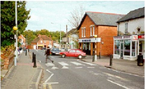
The zebra crossing is the oldest mid-block crossing type currently in use that gives priority to pedestrians. The important features of a zebra crossing can be seen in Figure 2. These consist of wide longitudinal strips to delineate the crossing, zigzag striping at the roadway edges and between lanes to indicate that parking and passing are not permitted, and black and white striped poles topped by flashing amber globes (Belisha beacons). These crossings may have other features such as a raised crosswalk, bulb-out, median refuge, and bollards. Pedestrians in a zebra crossing have priority over vehicles, but unlike in the U.S. and some other countries, U.K. motorists usually respect that priority and often stop for pedestrians who are waiting at the curb (and thus do not yet have priority) (10). Pedestrians may claim priority by standing in the crossing, which is different from most U.S. states where pedestrians are expected to wait for a gap before entering the roadway at uncontrolled crosswalks. Once a pedestrian claims priority in a zebra crossing, all vehicles that can do so are required to stop before entering the crossing.
Figure 2. Zebra crossing in the U.K.(10).
The pelican (PEdestrian LIght Controlled) crossing is reported to be the most common signaled-controlled crossing type in the U.K. (10). These crossings are similar to pedestrian-actuated signals that are used in the U.S., but there are several important differences between U.K. and U.S. signalized crossings. The most significant difference regards policy rather than design or operation. The pedestrian signal head is similar to that used in the U.S., having a green walking-man to indicate the walk phase, a flashing green walking-man to signal the end of the walk phase, and a red standing-man to indicate the no crossing phase. However, these phases are not regulatory – there is no offense for pedestrian violations of the do-not-start and do-not-cross phases. Williams (11) describes pedestrians who enter to crossing at the beginning of the flashing amber (standing-man) phase as “sheltered” by pedestrians already in the crosswalk. Three-color (red, amber, and green) signal heads are used to control vehicles at pelican crossings. The red phase is followed by a flashing amber phase that permits vehicles to proceed if pedestrians have cleared the crossing. Pelicans are both vehicle and pedestrian activated. Pedestrians press a button to request a walk phase. Sensors in the roadway hold the walk phase request until a gap in traffic is detected, or until the signal times out. As is typical at U.S. signal controlled crossings, pedestrian signal heads at pelican crossings are located on the far side of the crossing.
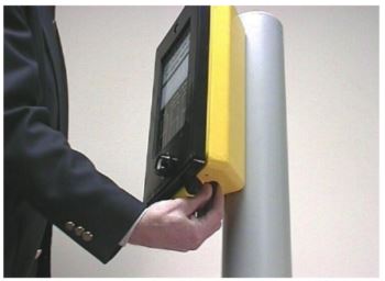
Puffin (Pedestrian User Friendly INtelligent) crossings are similar to Pelican crossings, but employ sensors to detect when pedestrians have cleared the crossing. This enables both shortening of the delay for traffic when pedestrians clear the crossing quickly, and extension of the walk phase when pedestrians need more time. Another difference between pelican and puffin crossings is that puffin crossings have the pedestrian signal head above the call button, which is on the near side of the crossing. Figure 3 shows a pedestrian signal call unit used in Dorset County, U. K. The pedestrian in the figure has his fingers on a rotating tactile cone that is intended to indicate the crossing phase to pedestrians who are blind, or deaf-blind. Because Puffin crossing visual indications are on the same side of the crossing as the pedestrian, pedestrians with low vision can often see these indications when they may not be able to detect or interpret far side signal indications found at Pelican crossings. (12) Puffin crossings may also have microwave, infrared, or pressure pad, detectors to sense pedestrians waiting to cross, and obviate the need for pressing a call button.
Figure 3. Pedestrian signal call device used at Puffin crossings.
Roundabouts in the U.K. may have any of the mid-block crossing types described here. Other types, Pegasus to accommodate equestrians, and Toucan, which combines bicycle and pedestrian crossings are not described here because the added capabilities they provide do not appear to affect accessibility for pedestrians.
Guidance on the design of U. K. roundabout pedestrian facilities is flexible, and suggests that the type of facility should depend on expected volumes of traffic and pedestrians (13). Unmarked crossings (defined by curb ramps), zebra crossings, signal controlled crossings, and grade separated crossings (i.e., pedestrian overpass or underpass) are all options to be considered. Where at-grade crossings are included, they are to be placed away from flared entries or exits. Figure 4 shows an example of a flared entry and exit design. The flared design is intended to increase roundabout vehicle capacity. The flared design may be compared to the design without flare shown in Figure 1. Placing the crossings beyond the flares minimizes the length of the crossings itself, but may increase the distance pedestrians need to travel on the sidewalks. For usability to pedestrians with visual impairments, crosswalks away from the flared portion of the entry and exit would have at least two potential benefits. First, where a double-lane roundabout is at the intersection of otherwise single lane roads, the crossing would be across single lanes, which eliminates the risk of being struck by a vehicle that passes a yielded vehicle. Second, beyond the flare, the roadway curbs are usually parallel, and thus curb cuts for ramps would provide a reliable cue for aligning with the crosswalk. One disadvantages for pedestrians would be the additional distance that needs to be traveled to reach the crossing. Another disadvantage is that pedestrians who are not familiar with the intersection might have difficulty in orienting to the indirect path. Figure 4 illustrates the difference in travel distance between the typical U.S. design and the U.K. practice. The red line that shows the pedestrian track for the typical U.S. design can be seen to be considerably shorter than the green line that shows the path in the U.K. design.
Figure 4. Explanation of flared entry and exit geometry.
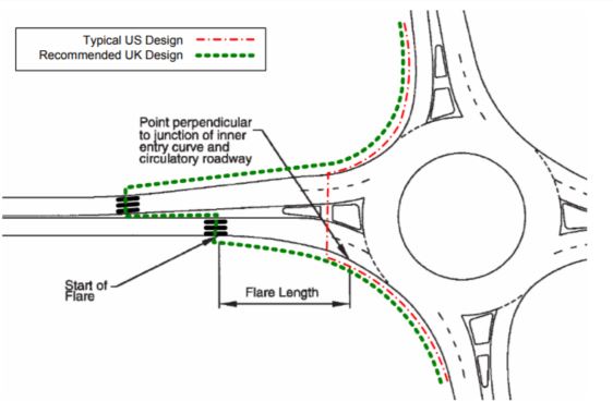
Figure 4 also illustrates another recommended U.K. practice, particularly for signalized roundabout crossings. That practice is the offset of the crossings for the two directions of travel (14). On roundabout exit lanes, queued vehicles that are stopped for pedestrians may “block back” into the circulatory roadway (15). The block back can drastically reduce roundabout capacity, as has been observed at the two U.S. roundabouts where crossings were signalized. Moving the exit crossing 50 m (164 ft) from the edge of the circular roadway reduces the chances that the vehicle queue will block back into the circular roadway. When signals are installed, the length of the red phase can be reduced by more than half by signaling the two halves of the crossing separately. The shortened red phases also minimize the chance of block back. To prevent pedestrians from continuing across the splitter island and into the lane that is not stopped, guardrails are installed to force pedestrians to use the offset crosswalk. Although, audible APS devices may be installed at these crossings, it would seem that tactile APS would avoid confusion between the separate indicators at each offset crosswalk. Because the crossing distances are short, and the crossings are perpendicular to the curbs, audible signals are probably not needed to provide directional guidance.
Personal communications with Barry Crown (16), who is currently a consultant, but previously conducted research for the Transportation Research Laboratory (TRL), provided information on the history of signalized crossings in the U.K. that were not readily available in the literature. According to Crown, signals are not installed at roundabouts to provide pedestrian access. Because U.K. drivers gave priority to pedestrians at the zebra crossings that were standard in urban roundabouts, the high volume of pedestrian traffic was causing roundabouts to lock up. Rather than to provide pedestrian access, signals were installed at roundabout pedestrian crossings to improve vehicle operations. When signals were first considered, there was fear that standard threelens signals (i.e., red, amber, and green lenses) might be problematic on approach legs. The concern was that because the signal would be relatively close to the approach yield line, motorists might misinterpret the green ball as overriding the yield control. In practice, this fear was not realized. Crown believes that because U.K. drivers were accustomed to the priority of circulating vehicles at roundabouts, the addition of signals only 7 to 10 meters upstream of the yield line did not confuse drivers. However, Crown was not confident that 3-lens signals would work in the U.S., because roundabouts do not have the long history here that they had in the U.K. before signals were introduced. He suggests a two-lens (i.e., red and amber) signal head might be more appropriate for signalized roundabout crossings in the U.S.
Recently, Transport for London Street Management published the results of a before after safety analysis of roundabout signalization (17). Overall, it was found that signalization of “standard” roundabouts resulted in a 28 percent decrease in crashes, which was statistically reliable at the 0.01 level. Like their U.S. counterparts, standard roundabouts give priority to circulating traffic, and have deflection at entry. However, standard roundabouts may have larger diameters than typical U.S. roundabouts, so that signalization would typically include placement of signals in the circulatory roadway and at entries. The London study included 36 months of observation in both the before and after periods. The largest crash reductions were for bicycle involvement (58 percent) and for merge collisions (58%). The reduction in pedestrian involved crashes (23 percent) was not statistically reliable. However, the baseline number of pedestrian-involved crashes over three years was already quite small (22 crashes). The U.K. crash reduction result may not be applicable to the U.S., in part because the roundabouts that were signalized tended to be larger than the “modern” roundabouts that are typical in the U.S. Nonetheless, the U.K. experience should refute the argument that signalization of roundabouts per se will result in decreased safety, or that signalization per se will put pedestrians at greater risk. The available empirical evidence suggests that signalization may enhance the safety of roundabouts and, does not put pedestrians at greater risk.
France
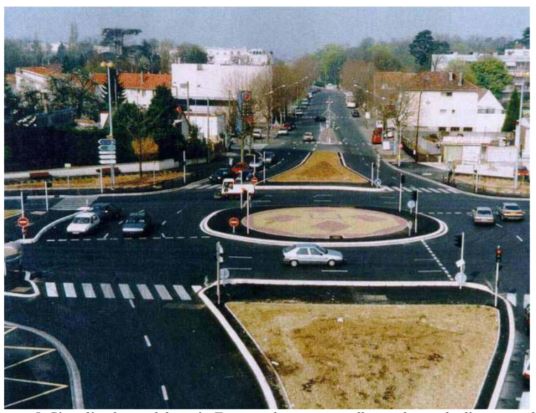
There are now more than 25,000 roundabouts in France. The French policy is to favor roundabouts over signalized intersections and to replace signalized intersections with roundabouts where that is feasible (18). The French guidelines for the design of urban intersections allow for signalization of roundabouts for pedestrian safety, but do not recommend signalization for pedestrian safety. Where a need for signalized crosswalks is identified, guidance on implementation is provided. However, guidance is not provided on how the safety need is to be established. Recent efforts at roundabout signalization have focused on integrating roundabout operations with at-grade train crossings that are in or near the roundabout. Where roundabouts have been signalized to accommodate traffic or train operations, crosswalks have been moved, in some cases, to be adjacent to the circular roadway, as can be seen in Figure 5. Although such a configuration would probably be preferred by pedestrians who use traffic surges and movements to identify the walk phase and crosswalk alignment, this configuration would not be feasible at typical U.S. roundabouts, which do not have space for storing stopped vehicles within the circulatory roadway.
Note that the traffic signals shown in Figure 5 are mounted on posts at the roadway edges, not on mast arms. Because of the low speed environment, it may not be necessary to locate roundabout traffic signals over the travel lanes to achieve adequate conspicuity.
The new French guidelines for urban intersections, to be published in 2006 (19), indicate that roundabouts may be signalized for pedestrian safety under the following conditions (20):
-
There is a splitter island that provides adequate pedestrian refuge between the two directions of vehicle travel.
-
The crosswalks are at least 49 ft from the circular roadway.
-
The two crosswalks are offset (same concept as illustrated in Figure 4, above).
-
The new French guideline also specifies that if the pedestrian crossings are signalized, release of vehicles should be immediate upon the pedestrian(s) clearing the crosswalk. The guideline does not specify how the clearing may be detected or the immediate release may be accomplished.
Figure 5. Signalized roundabout in France where crosswalks are located adjacent to the circular roadway. Note that France only allows post mounted signals. It is possible that overhead signals may be used in the US.(19)
Australia
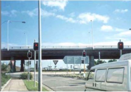
Baranowski has reported a roundabout in Sydney, Australia, that was designed to interrupt pedestrian flows that were anticipated to be heavy during the 2004 Olympic Games (14). Figure 6 shows one of the crossings at that roundabout. The crosswalks on either side of the splitter island are not offset, as recommended in the U.K. and France. According to Baranowski, the two-lens (amber and red) signals first flash amber, then goes to solid amber, and then to red. When not active, the signals are unlit (off). At the roundabout entrance, this avoids the confusion drivers might experience, if they received a green signal only a few feet upstream of the yield control. We have requested further information on the signal timing from the Australian contacts, as well as whether the configuration in the photograph is according to a VicRoads standard, or if it is experimental.
The signals are post-mounted. Two of the signals are mounted on posts at the stop bar, and two additional signals are mounted at the upstream side of the crosswalk. The two signals at the stop bar would emphasize the desired stop location, whereas the two signals at the crosswalk are far enough from the stop bar so that drivers can see them when stopped at the stop bar. Note, however, that the vehicle in the picture appears to have stopped upstream from the stop bar, perhaps so that the driver could maintain line of sight to all four signals. If drivers stop or slow well upstream of the stop bar, they may adversely affect roundabout operations, particularly for roundabout exit crossings where stopped vehicles would be likely to queue back onto the circulatory roadway.
In the U.S., the MUTCD requires that traffic signals be placed 40 ft beyond the stop bar to ensure that drivers who are stopped at the stop bar can see them. Signal heads at the stop bar, as shown in Figure 6, would be permissible in the U.S., as long as there are also yoked signals 40 ft beyond. It appears from the figure that the VicRoads standard may be similar to that in the MUTCD, as the two pairs of signals appear to be about 40 ft apart.
Figure 6. Signalized roundabout crosswalk in Sydney, Australia (14).
The Netherlands
Roundabout crosswalks in the Netherlands are not signalized. According to Martijn de Leeuw, a traffic engineer for the Province of South-Holland, the policy for intersections there is as follows (21):
-
Low volume intersections are normally single-lane roundabouts.
-
If a single-lane roundabout does not provide sufficient capacity, then a turbo-roundabout is considered.
-
If a turbo-roundabout does not provide sufficient capacity then a signalized intersection is considered.
-
If a signalized intersection will not provide sufficient capacity, then a signalized roundabout is considered.
Signalized roundabouts are only constructed when there is sufficient space to store vehicles in the circulatory roadway.
According to Mr. de Leeuw, “We have no problems with persons with visual impairment and the turbo-roundabout. The speeds are low.” However, in urban areas speed are low everywhere in comparison to the U.S. The urban speed limit is 30 km/h (18 mi/h). The Netherlands, and Europe in general, does not have civil rights laws that protect persons with disabilities and independent travel by the disabled is not a legal objective.
Turbo-roundabouts are used in locations where double-lane roundabouts might be used in the U.S. (22). Figure 7 illustrates a typical turbo-roundabout design. This design addresses the problem of path overlap, which is described in Chapter 6 of Roundabouts: An Informational Guide (7), by using mountable curbs between lanes, and using a portion of the central island for “left-turn” lanes. This design uses geometric barriers to force drivers to select the proper lane before entering the roundabout, and to stay in that lane until they exit. Figure 7 shows typical bicycle crossings on the west and south legs of the roundabout. These crossings employ a jog in the bicycle path on the splitter island that is intended to force bicyclists to go slow and encourage them to yield to oncoming traffic. Figure 8 shows a jog in a bicycle path on a turbo-roundabout splitter island. Pedestrian crossings at turbo-roundabouts do not employ the jog in the path because it is assumed that pedestrians travel slower than bicyclists do and therefore have sufficient time to recognize vehicles to which they should yield.
At-grade pedestrian and bicycle crossings at turbo-roundabouts are used when pedestrian and bicyclist volumes are low enough that vehicle traffic flow will not be disrupted. At turbo-roundabouts, which are typically used in rural locations, pedestrians and bicyclists are required to yield to vehicles. Figure 9 shows typical pedestrian and bicycle crossings at the exit of a turbo-roundabout. In urban environments, at-grade pedestrian crossings are usually zebra crossings, which, as in the U.K., give priority to the pedestrian. Where pedestrian and/or bicycle volumes are high, grade separation is the preferred solution to conflicts between pedestrian/bicycle and vehicle traffic flow at roundabouts (23).
Figure 7. Typical Dutch design for a turbo-roundabout (22).
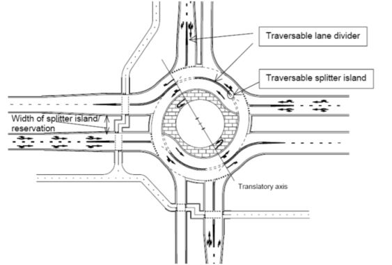
Figure 8. Jog in bicycle path in splitter island at turbo-roundabout (22).
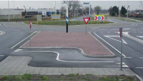
Figure 9. Typical juxtaposed pedestrian and bicycle crossing at a turbo-roundabout (22).
Sweden
We have requested additional information on Swedish policy and practice. At the time of this writing the available information is somewhat dated. The present information comes largely from a 1999 FHWA report on pedestrian safety in Sweden (24). Roundabouts are viewed as a safety enhancement for pedestrians because they serve to slow traffic and make driver yielding more likely. Nonetheless, studies of driver yielding behavior at roundabout zebra crossings suggest that, as in the U.S., most drivers do not yield to pedestrians (24).
Christer Hydén of the Lund Institute of Technology reports that there are very few signalized roundabouts in Sweden, with most of those in Stockholm. In those cases, only one leg is signalized. (25)
Per Garder of the University of Maine reports that the signalized roundabout crosswalks in Sweden flash amber until a pedestrian presses the button to call for a pedestrian crossing phase (26). Until the call button is pressed, the pedestrian signal head is either off, or indicates that a crossing is prohibited. When the button is pressed, two solid amber lenses are displayed to traffic. According to Garder, two solid ambers are required to call motorist attention to the end of the flashing amber phase. A walk phases is indicated to the pedestrian when the solid amber phase ends and a red signal lens is displayed to motorists.
INFORMATION REQUIREMENTS OF PEDESTRIANS WITH VISION DISABILITIES
In a review of accessible pedestrian signal devices, Bentzen and Tabor (12) provide a high level analysis of intersection information requirements of pedestrians who are blind. Requirements include identification of the sidewalk or roadway path, detection and identification of the intersection, and detection that the intersection is a roundabout. Although the accessibility of roundabouts depends on meeting a large number of information requirements, this report focuses only on requirements related to the availability and detectability of gaps in traffic.
In the absence of traffic signals, the pedestrian would need to either detect that no vehicles are approaching, or that vehicles are yielding in all lanes. Previous research has shown that at many roundabout crossings a substantial number of drivers fail to yield to apparently blind pedestrians (4) (5). Additional regulatory signage had only a small effect on driver yielding (4). Furthermore, research has shown that when vehicles do yield, visually impaired pedestrians cannot reliably tell whether vehicles have yielded in all lanes (4), or when crossable gaps are present because no vehicles are approaching (3). Accessible traffic signals would seem to be a logical alternative as these can reasonably be expected to (1) reliably stop most traffic and (2) provide notice to the pedestrian of when it is appropriate to cross.
The remainder of this report represents an attempt to integrate the above information. Recommendations are made for further research to support a rational approach to signalizing roundabouts where signals may provide needed pedestrian access.
GENERAL CONSIDERATIONS FOR TRAFFIC SIGNAL CONTROLLED ROUNDABOUT PEDESTRIAN CROSSINGS
Policy on Traffic Signals for Roundabout Crosswalks
Traffic signals at pedestrian crosswalks can be used in most of the jurisdictions surveyed in this report. Only in the Netherlands is there a policy against signalizing roundabout crosswalks except for fully signalized roundabouts (i.e., large roundabouts that have traffic signals within the circulatory roadway). Because the final decision on crosswalk signalization is left to Dutch provincial authorities, even in the Netherlands we cannot say with certainty that no roundabout crosswalks are signalized.
Among the jurisdictions surveyed, only the soon to be published French guideline suggests signalization may be considered for roundabout crosswalks to provide for pedestrian safety. Even so, the French guideline suggests that signals are not likely to make pedestrians safer, and that they might have the effect of making pedestrians overconfident and thus careless.
With the exception of France, the sole policy rationale this review identified for consideration of signalizing roundabout crosswalks is to improve traffic operations. No jurisdiction was identified that recommends traffic signals to improve roundabout access for pedestrians. The two operational rationales offered for signalization are: (1) to meter entering traffic when the volume is so high as to obstruct downstream entrances (e.g., the U.S.), or (2) to meter pedestrians so that traffic flow can be maintained (e.g., the U.K.). However, traffic signal Warrant 4 in the MUTCD (27) might be applied to specific roundabout crosswalks. That warrant requires that a traffic signal with pedestrian signal heads “shall be considered” if both of the following conditions apply: (1) the number of pedestrian crossings on an average day is at least 100 pedestrians in each of any 4 hours, or more than 190 pedestrians cross in any hour; and (2) there are fewer than 60 crossable gaps per hour during the peak times used to meet the pedestrian volume criterion.
The Effect of Roundabout Crosswalk Signalization on Vehicle Traffic Operations
In the U.S., in both cases where experience has been gained with signalization of roundabout crosswalks, the result was disruption of traffic operations, not enhancement. However, in both cases, the installations stopped both entrance and exit sides of the signalized leg at the same time. The result was the need for relatively long pedestrian crossing phases, and in turn, much longer vehicle queues than would have resulted if U.K. practice had been followed. In the U.K., exit and entrance crossing phases are separated in both time and space. The separation in time allows for short pedestrian crossing phases that result in shorter vehicle queues. For instance, consider a double-lane roundabout where there are four 12 ft wide lanes at the crossing, and the median is 12 ft wide. Assuming a minimum pedestrian phase for the entire crossing, the vehicles will have a red indication for (4 lanes + 1 splitter) × 12 ft ÷ 3.5 fps = 17 s. Whereas, if the U.K. guidance were followed the minimum red indication would be 2 lanes × 12 ft ÷ 3.5 fps = 7 s. Thus, if one vehicle per lane arrives every 3 seconds, in the former case 6 vehicles will queue up in each lane whereas in the latter case 2 vehicles will queue up in each lane.
The U.K. guidance to separate the exit and entrance crossings in space was originally intended to ensure that the pedestrians face into the oncoming traffic before crossing and to prevent pedestrians from continuing across the splitter island without checking traffic (16). As originally conceived, this would have located the exit crossing closer to the circulatory roadway than the entrance crossing. However, for operational reasons, the original configuration was reversed and the exit crossing was moved further from the intersection than the entrance crossing. Although this causes pedestrian to turn away from oncoming traffic when traversing the splitter, this design still achieved the goal of forcing pedestrians to make the crossing in two time-separated stages. Experience has shown that this configuration has not resulted in an increase in pedestrians stepping into the roadway without looking (16).
To allow traffic to queue up at the crossing without backing up into the circulatory roadway, the U.K. guidance suggests that the exit crosswalk be located about 164 ft from the edge of the inscribed circle. Such a location would allow for 4 to 8 passenger vehicles per lane to queue up before the queue would extend into the circular roadway. This amount of storage space may be appropriate where there is a high volume of pedestrians, as is the case where roundabout crossings are signalized in the U.K. However, at typical U.S. roundabouts the number of pedestrians crossing in a single phase is small (e.g., fewer than 10). Where storage requirements are less, the offset of the exit crossing could be lower, perhaps no more than 50 ft, which would allow a queue of about 2 to 3 passenger vehicles per lane. This contrasts with current-typical U.S. practice of locating the crosswalk 20 ft. from the circulatory roadway, which allows for storage of no more than one vehicle per lane.
Offset Crosswalk Considerations
One objection to moving the exit crosswalks 30 or more feet farther from the intersection is that pedestrians would be unlikely to walk the additional distance and might therefore jaywalk. In the U.K. jaywalking itself is not recognized as a traffic offense. So to some extent, if the jaywalking does not disrupt traffic, it is not a concern. However, jaywalking can disrupt traffic at times, and if a vehicle strikes a pedestrian, the disruption to traffic, as well as the life of the pedestrian, could be extreme. To limit jaywalking where crosswalks are offset, fences are often installed on the splitter island and on the sidewalks on both sides of the street. The fences steer pedestrians to the crosswalk. Slats in the fences are angled such that they do not obstruct the line of sight between drivers and pedestrians.
Another objection to moving the crosswalks further from the inscribed circle is that it increases pedestrian travel time. If all other things are equal, and a 3.5 fps walking speed is assumed, then moving the crosswalk 30 ft farther from the inscribed circle would add 8.6 s to the pedestrian travel time, or about 17 s if the pedestrian continues down the same street on the opposite side of the intersection. The U.K recommended 164 ft offset would add 47 s to a pedestrian travel time to the crosswalk, or 1.5 minutes if it is assumed that the pedestrian would then continue walking down the same street on the opposite side of the intersection. At exits where the crosswalk is not signalized, vehicle speed is likely to increase with increasing distance from the circular roadway. For instance, a vehicle is traveling 20 mi/h at the inscribed circle and accelerates according to the profile suggested by AASHTO design policy (28), then 164 ft from the inscribed circle the vehicle can be expected to be traveling at about 32 mi/h. At signalized crossings where vehicle and pedestrian behavior should be controlled by the signal, the speed increase that results from the increased travel distance may not be a major concern unless compliance with the signal is problematic.
Adding a travel distance of almost 300 ft and 1.5 minutes to travel time might be considered unreasonable. However, it should be noted that the offset is recommended when traffic signals are installed, and traffic signals themselves can add to pedestrian delay because the pedestrian must wait for a crossing call to initiate the walk phase.
Where pedestrian traffic is heavy, the crossing phase must be longer to accommodate all the pedestrians who need to cross. The longer the crossing phase, the greater the probability that the traffic queue will disrupt the operation of the roundabout and reduce intersection capacity. Thus, where pedestrian traffic is high, the exit crosswalks need to be farther from the inscribed circle, perhaps as far as the 164 ft recommendation in the U.K. guideline. The farther the exit crossing is from the circular roadway, the greater the number, and the longer, pedestrian walk phases that can be accommodated. Depending on the tradeoffs that are made between walk phase frequencies, walk phase duration, vehicle delay, and pedestrian travel distance, the longer crossing offsets might result in longer, shorter, or no change in pedestrian delay relative to keeping the crossing closer to the inscribed circle.
Traffic signals can reduce pedestrian delay under certain conditions:
-
When the arrival of vehicles would otherwise be constant and drivers will not yield.
-
When a pedestrian who relies on non-visual cues cannot detect available gaps without the assistance of an accessible traffic signal.
Inman et al. (29) reported that at a double-lane roundabout exit where the flow was about 800 vehicles per hour, it took a mean of 63 seconds before vehicles yielded in both lanes (range 6 to 243 s). Blind pedestrians took an average of 3 seconds to recognize that both lanes were blocked (range 0 to 27 s). Thus, without a traffic signal the average delay for blind pedestrians in that study was 66 s, exclusive of the time it may have taken those pedestrians to locate the crosswalk and orient to the intersection. Thus, with or without a traffic signal, and with or without added crosswalk offsets, some pedestrians may experience delay at roundabout crosswalks, particularly during peak traffic periods. Whether the installation of traffic signals with crosswalk offsets similar to those used in the U.K. would increase or decrease pedestrian delay would depend on a number of factors that include:
-
The willingness of drivers to yield in the absence of signals.
-
The volume of vehicle traffic at the intersection.
-
How long it takes the pedestrian to accept an available gap, either from yielding vehicles or detection of a gap between arrivals.
-
The delay between the time a pedestrian phase is called (e.g., the pedestrian pushes a button) and the onset of the walk phase.
-
The walking speed of the pedestrian.
-
The distance of the crosswalk from the edge of the circulatory roadway.
Traffic Signal Configuration Considerations
Standard three-lens traffic signals that operate full time could be used at roundabout crosswalks. This three-lens signal is the only one that currently conforms to the MUTCD standard, which may be found in section 4D of that publication (27). If the roundabout is to continue to give priority to circulating traffic, i.e., retain yield at entry control, then great care must be taken in installing signals at nearby crosswalks. Standard three-lens signals have been used successfully at U.K. roundabout crossings. However, Barry Crown, a leading authority on U.K. roundabouts, has warned that the successful implementation in the U.K. may not be applicable to the U.S., because in most areas of the U.S., drivers are not familiar with the priority rule at roundabouts. U.K. drivers had many years of experience with the roundabout priority rule before the first pedestrian traffic signal controls were installed. Despite the initial fears of U.K. engineers, U.K drivers did not misinterpret the green indication at crosswalks as overriding the yield control at roundabout entries. Such might not be the case in the U.S. where drivers are often naive to the priority rule.
In an apparent recognition of the potential for driver misinterpretation of green signals at a roundabout crosswalk, engineers in Victoria, Australia, installed two-lens signals that omitted the green indication. The Australian two-lens signal is blank until called by a pedestrian. When a pedestrian presses the call button, the amber light flashes to get drivers’ attention, then burns steady amber to indicate that a red light is imminent.
The Australian approach appears to be logical, easy to understand, and in the context of a roundabout entrance, more appropriate than a standard three-lens signal. However, the MUTCD only provides for two-lens signals at freeway onramps, and there, red and green lenses are prescribed, not red and amber. Furthermore, the MUTCD standard does not allow for the use of part-time traffic control signals. A signal that is blank until called by a pedestrian is not MUTCD compliant. The MUTCD calls for traffic signals that are not needed at all times of day to be in flash mode, when a traffic signal is not required. Leaving the amber light in flash mode when no pedestrians have requested a crossing-phase might meet the MUTCD standard for not having visible inactive signals, but it is not clear whether a flash mode would make the traffic signal more effective when it is needed. It is plausible that a normally inactive signal that begins to flash would be more effective in attracting driver attention, and in attaining subsequent compliance, than a light that constantly flashes and on rare occasions goes to steady amber. However, the Swedish approach of following one flashing-amber with two steady ambers may be a viable alternative to inactive signals.
Placement of the traffic signal heads needs to be considered for effectiveness, driver comprehension, and cost. The MUTCD standard calls for a minimum of two signal faces. This could be accomplished by placing signal faces over each lane of a double-lane roundabout, or signal faces on poles on each side of the road. The MUTCD standard requires that the distance between the stop bar and at least one of the signals be a minimum of 40 ft. On roundabout approaches where the typical crosswalk is about 20 ft upstream for the yield line, this would place a traffic signal face quite close to the yield line unless the stop bar were placed well upstream of the crosswalk. Placement of a traffic signal at or near the yield line could cause driver misunderstanding of the yield requirement, even if a green indication is not present. Therefore, at a minimum, a signal face should not be easily visible to drivers who are at or near the yield line.
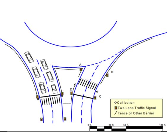
Figure 10 shows a possible pedestrian signal configuration for double-lane roundabout crossings. The configuration follows the U.K. practice of offsetting entry and exit crossings. It also employs barriers to ensure that pedestrians observe the offset, places at least one signal 40 ft from the stop bar, shows pedestrian call buttons on the upstream (relative to vehicle traffic) side of the crosswalk threshold, and locates additional signal faces at the stop bars to emphasize stop bar location. The figure, which is roughly to scale, shows the exit crosswalk set back 50 ft from the circulatory roadway. The stop bar at the exit crosswalk is set close to the crosswalk to maximize the usable vehicle storage capacity. The stop bar at the entrance is set back away from the crosswalk to enable placement of signal faces on the side of the road 40 ft from the stop bar. To move the stop bar closer to the crosswalk would require either (a) moving the crosswalk further from the circular roadway, or (b) installing an overhead signal that would extend above the circular roadway and might be visible from the yield line.
Figure 10. Hypothetical pedestrian crossing signal configuration for double-lane roundabout crosswalk.
The pedestrian crossing-interval call button, shown in Figure 10 on the side of the crosswalk thresholds closest to the approaching traffic, follows the U.K. and Dutch practice of placing the buttons so that the pedestrian faces oncoming traffic when the button is pressed. In those countries, puffin style displays are used above the call button. These displays show the walk and don’t walk symbols on the call button housing, as illustrated in Figure 3. A device on the call button housing would signal the walk interval using vibro-tactile methods. Because the crossing of the entrance and exit portions of a roundabout leg would require time separated crossing intervals, it would be necessary to make audible indications for each half of the crossing (exit and approach) easily distinguishable. Offsetting the crosswalks facilitates compliance with MUTCD (27) guidance to ensure that call buttons with tones are separated by at least 10 ft. Bentzen and Tabor (30) provide an extensive review of the technical issues and available hardware for accessible pedestrian crossing signals. Issues discussed include placement of the call button, the nature of the crossing-interval notification, and the usability of the devices for visually impaired persons. More recently, National Cooperative Highway Research Project 3-62 produced a synthesis report on accessible pedestrian signal best practices which can be found at http://www.walkinginfo.org/aps/ (31). The discussion here is intended to highlight some of the issues that need to be addressed to provide accessible pedestrian signals at roundabouts.
The Cost of Signalization
Roundabouts have been shown to provide substantial safety and operational benefits. However, their accessibility to visually impaired pedestrians has been shown to be problematic. This review has shown that if traffic signals were installed to provide access, the signals would not necessarily disrupt intersection operations, and in some cases – when pedestrian volumes are high, or traffic volumes are unbalanced across approaches—might improve operations. Nevertheless, installation of roundabout intersections is not the default choice in most U.S. jurisdictions, although several states have policies to encourage the consideration of roundabouts ahead of other intersection alternatives (e.g., New York, Virginia, and Kansas). Engineers usually have alternatives to roundabouts for solving intersection problems, and cost is a factor in design tradeoffs. Although cost may not be a factor in determining whether a new or altered intersection is designed to be accessible, it may be a factor in determining how accessibility is addressed. It is conceivable that double-lane roundabouts with accessible traffic signals would provide superior access relative to a traditional signalized intersection that is designed to carry the same volume of traffic movements.
The cost of installing mast arm signals at traditional intersection is about $150,000. The cost of such an installation at a four-legged roundabout would be approximately $600,000 under the assumption that each leg operates independently as a conservative estimate. The configuration shown in Figure 10, which does not require mast arms, would cost less. Figure 11 shows a solar powered unit that would be off when not activated by a pedestrian call and would flash amber, and then show steady amber, and then red when activated. All the signals at a crossing could be controlled through radio communication. The solar powered unit would have low installation cost because it would not require trenching to supply power or to control the remote signal faces. The manufacturer of the solar powered unit provided an estimate of $2,775 for a unit with two eight-inch lenses, solar panel, batteries, control logic, and radio. This estimate does not include the accessible pedestrian signal call unit or signal, mounting pole, or installation. A Virginia Department of Transportation manager estimated that the cost of installation of similar devices that do not require trenching is about $1,500.
Figure 11. Two-lens solar powered pedestrian crossing signal.
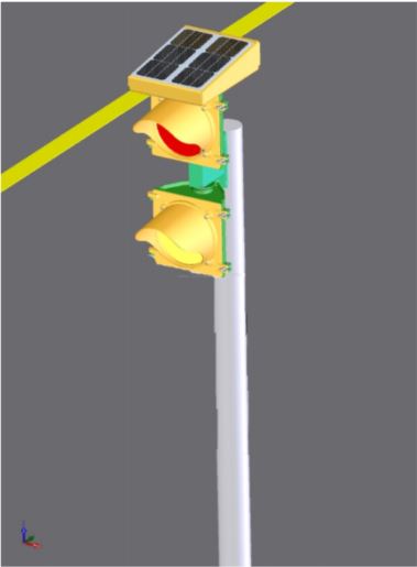
Table 1 provides a rough estimate of what it might cost to signalize a multilane roundabout to provide access to pedestrians with visual impairments. The estimate includes the typical cost of installing solar powered signals at the roadside, a two-lens solar-powered signal, and an accessible call button unit (32). The lower right cell of the table shows the estimated cost for installing signals as depicted in Figure 10 at four legs of a roundabout. The table also provides estimates for signalizing one, two, or three legs, and for providing fewer that four signal faces at each crossing segment. The MUTCD requires a minimum of two signal faces. Four faces were included in the hypothetical intersection shown in Figure 10 under the assumption that this might be important to ensure detection and compliance.
The estimate does not include the cost of: (1) installing barriers to prevent pedestrians from crossing at locations other than the crosswalk; (2) drilling through concrete or other work that might be required to install mounting poles in difficult locations; or (3) maintenance or operations. Because ADA standards govern only new constructions or alterations, the estimate does not include the cost to modify an existing roundabout, such as the cost of moving crosswalks and ramps.
Research is recommended to determine whether four faces are required to maximize performance (i.e., detection and driver compliance). It is possible that equal performance could obtain with only two faces, those labeled B and D in the figure. If two signal faces are sufficient, then the cost of installation would be about 30 percent less than with 4 faces.
| Number of Signal Faces | 1 Leg | 2 Legs | 3 Legs | 4 Legs |
| 2 Signal Faces | $ 24,200 | $ 47,900 | $ 71,600 | $ 95,300 |
| 3 Signal Faces | $ 29,750 | $ 59,000 | $ 88,250 | $ 117,500 |
| 4 Signal Faces | $ 35,300 | $ 70,100 | $ 104,900 | $ 139,700 |
RESEARCH NEEDS
Research is needed to determine whether signal faces mounted at the roadside will be effective in the roundabout context.
Research is needed to determine the minimum number of signal faces necessary to achieve high driver compliance.
Guidelines for computing the optimal location of the stop bar are needed.
U.S. Access Board has identified signalization as the only proven means of creating crossable gaps in traffic and providing audible cues to pedestrians of the availability of gaps. Although there is extensive experience with traffic signals both in the U.S. and abroad, experience with traffic signals at roundabout crosswalks is limited, and experience with signals to provide access at roundabout crossings to persons with visual or other disabilities is non-existent. Therefore, although it is reasonable to expect that accessible traffic signals will be effective at multilane roundabouts where access is otherwise problematic, the lack of implementation experience suggests the need for studies to document potential pitfalls and best practices.
U.K. experience suggests that drivers will not confuse the pedestrian crossing signals with the yield at entry control, but this needs to be verified with U.S. drivers.
It was suggested above that a signal face that is blank (off) until activated by a pedestrian would be more effective that a signal that flashes amber until activated. This suggestion was based on the assumption that drivers would learn to expect the flashing amber, and thus be less likely to detect when a pedestrian call had caused the light to become steady. The MUTCD recommends a flash rate of about 1 Hz (about 0.5 s on and 0.5 s off). The off cycle distinguishes flashing amber from a solid. It would probably take well in excess of 0.5 s for a motorist to detect that the off cycle was not coming, particularly if the motorist was not expecting a phase change. At a minimum, the onset of the flashing amber would reduce motorist recognition time by approximately 0.5 s. The reduction in reaction time might be much greater for motorists who are not anticipating a phase change. These considerations suggest an evaluation of the effectiveness of blanking out the signal when not in use versus flashing amber when there is no pedestrian call.
The precedent for a blank pedestrian crossing signal is the High Intensity Pedestrian Activated crossWalK (HAWK) signal that is currently in use in Tucson Arizona (33). This crossing control, which has approval from FHWA as an experimental device, consists of two red lenses over an amber lens. When a pedestrian presses the call button, the amber flashes for three seconds, then turns solid for four seconds. The solid amber is followed by two solid red lenses that are illuminated for the duration of the walk phase on the pedestrian signal head. At the beginning of the flashing do not start phase on the pedestrian signal head, the red lenses on the traffic signal begin alternating. Depending on the length of the walk phase, the HAWK signal may, or may not be appropriate for roundabout accessibility. Because the flashing red phase is a stop control—drivers may continue after coming to a complete stop. Under stop control, vehicles may proceed when it is safe to do so. Blind pedestrians often wait and listen for assurance that vehicles have stopped for them. Drivers may interpret this delay as a decision by the pedestrian not to cross, and proceed just as the pedestrian steps into their path. An APS indication of the crossing-interval might not be appropriate with a stop control, because vehicles will still be permitted to proceed after stopping. Because roundabout crossings are short, the flashing red phase may not be necessary with HAWK type signals at roundabouts. Evaluation of the HAWK crossing in Tucson, which is not at a roundabout, showed that driver yielding increased from about 34 percent with an uncontrolled crossing to between 93 and 97 percent with the HAWK, and that pedestrians were less likely to run or hesitate during their crossings after the HAWK was installed (34).
SUMMARY AND CONCLUSIONS
Signalization is used to enhance the operational efficiency of roundabouts where pedestrian traffic causes unacceptable vehicle delay and where the volume of traffic from one entry is so high as to cause unacceptable queues at downstream entries. No evidence was identified to suggest that a properly designed signal system would degrade roundabout traffic operations. When traffic signals are installed that stop both entry and exit traffic at the same time while pedestrians cross both directions of traffic, queues back up into the circulating roadway and disrupt traffic operations. Stopping both directions of traffic at the same time is generally not done outside the U.S.
The only study identified that addressed the effect of signalization on roundabout safety showed a marked improvement in safety for vehicles and bicyclists, with no degradation in pedestrian safety.
Solar powered traffic signals that operate only when called by pedestrians could be installed at four legs of a multilane roundabout for about $140,000. The actual cost could be less, if fewer than four signal faces are used at each crossing. Additionally, if pedestrian traffic is unbalanced, then crosswalks can be omitted from some legs and substantial signalization cost reductions can obtain.
It should be not
Additional research is needed to support signal implementations that do not meet current MUTCD standards. This includes research into the effects of using two-lens amber-red signals instead of red-amber-green signals, and study of the effects of only operating the signals when the pedestrian call button is pressed. Research is also needed to verify that U.S. drivers will comply with roundabout signals, and that drivers will continue to observe the circulating traffic priority rule after responding to pedestrian traffic signals.
REFERENCES
-
United States Department of Justice. 2005. ADA Home Page. Retrieved September 30, 2005, from http://www.ada.gov/.
-
United States Access Board. 2005. Pedestrian Access to Modern Roundabouts. Retreived August 30, 2005, from http://www.accessboard.gov/research&training/roundabouts/bulletin.htm#IMPROVEMENTS%20W ORTH%20INVESTIGATING.
-
Guth, D., D., Ashmead, R. Long, and P. Ponchillia. 2005. Blind and Sighted Pedestrians’ Judgments of Gaps in Traffic at Roundabouts. Human Factors 47(2):314-342.
-
Inman, V. W., G. W. Davis, and D. Sauerburger. 2005. Roundabout Access for Visually Impaired Pedestrians: Evaluation of a Yielding Vehicle Alerting System for Double-Lane Roundabouts. Proceedings, National Roundabout Conference, Vail, CO.
-
Geruschat, D. R., and S. E. Hassan. 2005. Driver Behavior in Yielding to Sighted and Blind Pedestrians at Roundabouts. Journal of Visual Impairment & Blindness 99(5):286-312.
-
U. S. Access Board (2005) Public Rights-of-Way Guidelines. Retrieved June 28, 2006 from http://www.access-board.gov/prowac/draft.htm.
-
Robinson, B. W., R. Troutbeck, B. Werner, B. Lothar, , K.Courage, M. Kyte, J. Mason, A. Flannery, E. Myers, J. Bunker, G. Jacquemart. 2000. Roundabouts: An Informational Guide. Document Number FHWA-RD-00-067, Federal Highway Administration, McLean, VA.
-
Transportation Research Board. 2005. NCHRP Project 3-78, Crossing Solutions at Roundabouts and Channelized Turn Lanes for Pedestrians with Vision Disabilities. Retrieved January 10, 2006, from http://www4.trb.org/trb/crp.nsf/e7bcd526f5af4a2c8525672f006245fa/575b1ad6aa4 ad3fd85256960006de0cb?OpenDocument
-
Myers, E., L. Redegerdts, and E. Ferguson. 2005. Literature Review: Signalization to Provide Roundabout Access. Memorandum: Kittleson & Associates, June 29, 2005.
-
Davies, D. G. 1999. Research, Development, and Implementation of Pedestrian Safety Facilities in the United Kingdom. Document Number FHWA-RD-99-089, Federal Highway Administration, McLean, VA.
-
Williams, M. C. 1984. Effects of Converting a Zebra to a Pelican Crossing. TRRL Supplementary Report 830, Transport and Road Research Laboratory (TRRL), Crowthorne, Berkshire, UK.
-
Bentzen, B. L., and L. S. Tabor. 2005. Accessible pedestrian signals. American Council of the Blind. Retreived August 18, 2005 from http://www.acb.org/pedestrian/signals.html.
-
Brown, M. 1995. The Design of Roundabouts. H.M.S.O., London.
-
Baranowski, B. 2004. Pedestrian crosswalk signals at roundabouts: Where are they applicable?. Report presented at ITE District 6 Annual Meeting.
-
Marlow, M., and G. Maycock. 1982. The Effect of Zebra Crossings on Junction Entry Capacities. TRRL Supplementary Report 724, Transport and Road Research Laboratory, Crowthorne, Berkshire, U. K.
-
Crown, B. 2005. Re; signalized roundabout crossings. Personal communication, email to V. W. Inman, received September 7, 2005.
-
Transport for London Street Management. 2005. Do Traffic Signals at Roundabouts Save Lives? Transportation Professional (April 2005).
-
Guichet, B. 2005. Evolution of Roundabouts in France and New Uses. Proceedings, National Roundabout Conference, Vail, CO.
-
Guichet, B. 2005. Roundabouts in France: Safety and New Uses. Presentation at National Roundabout Conference, Vail, CO.
-
Guichet, B. 2005. Section on Carrefours with traffic signals. Personal communication. E-mail received August 23, 2005 by V. W. Inman
-
de Leeuw, M. 2005. Signalized Roundabouts. Personal communication. E-mail received September 9, 2005 by V. W. Inman.
-
Fortuijn, L. G. H. 2003. Pedestrian and Bicycle-Friendly Roundabouts; Dilemma of Comfort and Safety. Institute of Transportation Engineers 2003 Annual Meeting and Exhibit, Seattle, Washington.
-
Fortuijn, L. G. H., and P. J. Carton. 2005. Turbo Circuits: A well-tried concept in a new guise. Unpublished manuscript.
-
Ekman, L., and C. Hydén. 1999. Pedestrian Safety in Sweden. Document Number FHWA-RD-99-091, Federal Highway Administration, Washington, DC.
-
Hydén, C. (2005). Personal communication. E-mail received December 6, 2005 by V. W. Inman.
-
Garder, P. 2005. RE: FWD: [ITETRAFFIC] Ped Signals at Multi-Lane Roundabouts. Message posted on Roundabouts@LISTSERV.KSU.EDU on 12/21/2005.
-
Federal Highway Administration. 2003. Manual on Uniform Traffic Control Devices for Streets and Highways - 2003. Federal Highway Administration, Washington, DC.
-
American Association of State Highway and Transportation Officials. 2001. A Policy on Geometric Design of Highways and Streets. Washington, D. C. See exhibit 2-24.
-
Inman, V. W., G. W. Davis, and D. Sauerburger. (in press). Pedestrian Access to Roundabouts: Assessment of Motorist Yielding to Visually Impaired Pedestrians and Potential Treatments to Improve Access. Report Number FHWA–HRT–05– 080, Federal Highway Administration, McLean, VA.
-
Bentzen, B. L., and L. Tabor. 1998. Accessible Pedestrian Signals. Accessible Design for the Blind, Berlin, MA
-
Walkinginfo.org. 2006. Retrieved from http://www.walkinginfo.org/aps/, November 1, 2006.
-
Mack, L. 2005. Cost estimate for Navigator APS. Received from Polara Engineering, Inc., Fullerton, CA., on November 13, 2005.
-
Tucson Department of Transportation. 2005. Retrieved from http://dot.tucsonaz.gov/traffic3/tspedestrian.cfm, September 12, 2005. 34. Nassi, R. B. 2005. Bird Watching Tucson Style., PowerPoint presentation received January 10, 2006.
User Comments/Questions
Add Comment/Question