Recommendations on Standards for the Design of Medical Diagnostic Equipment for Adults with Disabilities, Advisory Committee Final Report
5.8.2.7 Base Support Allowance Recommendation
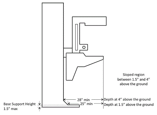
The Committee recommends allowing a base support that obstructs the clear floor space if it fits within the allowed base support volume. Base supports can be a maximum of 1½ inches high. An additional sloped region above the base support is permitted at a depth of 25 inches from the front edge of the breast platform at 1½ inches above the floor, and can extend to a height of 4 inches above the floor at a depth of 28 inches from the front edge of the breast platform. Figure 5.8.2.7(a) illustrates this configuration below.
Figure 5.8.2.7(a) Illustration of final committee recommendation on proposed base support configuration.
(SOURCE: Hologic, Inc.)

Rationale for the recommendation
The base support is of fundamental importance to mammography equipment and provides structural support, seismic stability, and installation safety. It does obstruct the floor space in front of the gantry and, thus, may limit how close a wheelchair can get to the equipment. To respond to this issue, industry proposed a configuration that would cause minimal obstruction to the floor space in front of the gantry and would allow footrests to ride over it.
To discuss the maximum base support height, the sub-committee looked at anthropomorphic data regarding footrest heights. The footrest height data measures the height from the floor to the top surface of the footrest at its proximal outside corner. To determine the necessary clearance for the footrests, the Committee used the footrest height data and subtracted the thickness of the footrests (~0.5 inch). The ~0.5inch thickness is the recommendation from the data supplied by Steinfeld and D’Souza7. The anthropomorphic data, as well as the calculated footrest clearances, is below in Tables 5.8.2.7(a) and 5.8.2.7(b).
Table 5.8.2.7(a). Anthropomorphic data on measured footrest heights
| Device Type | Min | 5% | 10% | 50% | 90% | 95% | Max |
| Manual (n=101) | 1.2 | 1.7 | 2.2 | 4.1 | 7.2 | 10.0 | 36.2 |
| Power (n=67) | 1.8 | 2.7 | 3.1 | 4.8 | 8.8 | 10.5 | 16.9 |
Table 5.8.2.7(b). Actual footrest height clearances
| Device Type | Min | 5% | 10% | 50% | 90% | 95% | Max |
| Manual (n=101) | 0.7 | 1.2 | 1.7 | 3.6 | 6.7 | 9.5 | 35.7 |
| Power (n=67) | 1.3 | 2.2 | 2.6 | 4.3 | 8.3 | 10 | 16.4 |
Allowing a maximum base support height of 1.5 inches will provide room for the structural components necessary for an effective base support design and will also be accessible by around 92% of manual chair users and over 95% of power chair users.
Committee members noted that allowing the base support to encroach into the floor space creates an exception from the 2010 Standards. Since mammography equipment bolts or affixes to the floor of the facility, it becomes a fixture to the building. The Department of Justice considers fixtures to fall under the architectural elements covered by the 2010 Standards. The provisions for clear floor space generally do not allow an encroachment even with a maximum height of 1½ inches for the base support. However, the Committee agreed that since the base support is critical to the equipment’s stability and installation safety, the support must be configured to allow for maximum wheelchair accessibility.
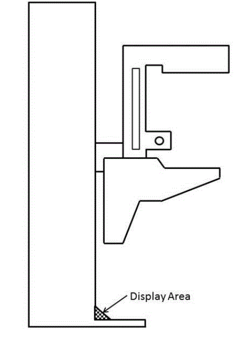
The Committee also discussed adding an allowance for a sloped region at the base of the gantry. Many of the mammography machines today have important informational displays at the base of the gantry, on top of the base support (shown as the checkered region in Figure 5.8.2.7(b)) that display information such as compression force and compression thickness.
Figure 5.8.2.7(b) Checkered region shows location of informational displays and other mechanical and electrical components on many mammography machines.
(SOURCE: Hologic, Inc.)

The Committee discussed the additional sloped region. Several members felt strongly that the additional sloped region must be justified by structural stability since displays could be located elsewhere. Members commented that not all equipment has displays in this region, so it seemed possible for industry to redesign the displays to create less interference.
Industry input indicated that customer feedback was one of the major drivers to position the displays at that location. Technologists have reported that while positioning the patient’s breast, they are naturally looking downward, and by having the display at the base of the gantry, they could watch the compression force and breast thickness readout while positioning the patient. They suggested this location for the display as a method for improving workflow. On other machines, this region has other mechanical and electrical components that are not necessarily there for structural stability, but are important to the function of the equipment.
The Committee refined the configured allowance for the sloped region from 7 inches down to a height of 4 inches above the floor at a depth of 28 inches from the front edge of the breast platform. Industry worked with Committee members to optimize the accessibility of the base support configuration, shown in Figure 5.8.2.7(a) above. The Committee agreed to accept the refined configuration during the full discussion of the report with no reference to structural stability.
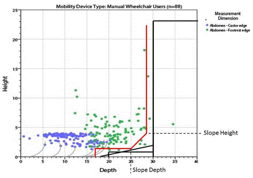
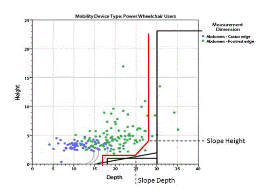
Figures 5.8.2.7(c) and 5.8.2.7(d) illustrate this region overlaid with the anthropomorphic data for manual and motorized wheelchairs, respectively. Steinfeld and D’Souza supplied these charts plotting their study’s findings on the depth of participant’s footrests and caster wheelsvii. The black lines show the areas with no interference between the footrests and caster wheels and the base support interface. However, based on the technical feasibility and clinical use considerations discussed in the above sections, industry proposed the overlay configuration in red in the figures.
Figure 5.8.2.7(c) Final Committee recommendation on allowable base support configuration overlaid with anthropomorphic data for manual wheelchairs.
(SOURCE: Hologic, Inc.)
The black lines show the areas with no interference between the footrests and caster wheels and the base support interfacevii. However, based on the technical feasibility and clinical use considerations discussed in the above sections, industry proposed the overlay configuration in red.

Figure 5.8.2.7(d) Committee recommendation on allowable base support configuration overlaid with anthropomorphic data for power wheelchairs.
(SOURCE: Hologic, Inc.)
The black lines show the areas with no interference between the footrests and caster wheels and the base support interface. However, based on the technical feasibility and clinical use considerations discussed in the above sections, industry proposed the overlay configuration in red.

The green dots in the scatter plot illustrations represent observed values for footrest height (on the vertical axis), and footrest depth (on the horizontal axis) measured for manual wheelchair users to the abdomen point. The footrest heights do not account for the 0.5-inch footrest thickness, so the required footrest clearances are 0.5 inch lower than the footrest heights plotted here. The footrest depth is the horizontal distance from the abdomen to the distal (forward-most) edge of the footrest. The person’s toes, however, will extend beyond the front edge of the footrests, so the Committee reviewed different data to determine the overall knee and toe clearance (see Section 5.8.2.3 above).
5.8.2.7.1 Mammography Chair Footrest Recommendation
The Committee recommends that the mammography chair meet the elements of M302 with the additional requirement that any footrests must accommodate and ride over the base support.
Rationale for the recommendation
The mammography chair is an essential piece of equipment allowing persons who are unable to stand or balance to sit for the diagnostic procedure. The chair must meet the elements of M302 with the additional requirement that any footrests must accommodate and ride over the base support.

User Comments/Questions
Add Comment/Question