2.1.4 Issues
* Only about 30 percent of modern hearing aids in the United States include a telecoil (more than twice this number use telecoils in Europe, which may help explain the popularity of IL systems there). As useful as telecoils are, with the trend toward smaller and smaller hearing aids, it seems unlikely that this 30% figure will increase in the future. Given the potential advantages of telecoils, not only for IL systems and telephones, but for all other types of ALS as well, it is unfortunate that a higher percentage of hearing aids do not routinely incorporate them. However, unless there is a drastic change in the type of hearing aids used by hard of hearing people, it does not appear that the use and popularity of IL systems will significantly increase.
* Even when a hearing aid includes a telecoil, it is quite likely that its electroacoustic performance will not duplicate the hearing aid's microphone response (Rodriguez, Holmes & Gerhardt l985; Culpepper l986; Thibodeau & Abrahamson l988). However, recent developments in hearing aids suggest that this variable can be circumvented, either by programming the telecoil to match the microphone response (Davidson & Noe l994) or by using amplified telecoils (Noe, Davidson & Mishler 1997).
* Complicating telecoil usage is its physical orientation within the hearing aid. For optimal sensitivity to an IL system, the telecoil should be mounted perpendicular to the floor loop (or a neckloop). But since optimal sensitivity for detecting the electromagnetic field around a telephone occurs when the "T" coil is in the horizontal position, a positional compromise is often necessary (Preves, l994).
* The newest telecoil standards (revision of ANSI S3.22) provide for measurements in which the extent of any compromise can be determined. In this new standard, the high frequency average (HFA) gain in the microphone position of the hearing aid is explicitly compared to both simulated telephone and induction coil usage (Preves 1996). The differences are expressed as Simulated Telephone Sensitivity (STS). A zero figure means that at the same gain control setting, the high frequency average gain in the microphone position was equal to that obtained in the telecoil position. Usually, the STS is negative, indicating that the gain must be increased in the telecoil position to achieve the same results as in the microphone position. Preves (l996) points out that the STS can be positive with the use of preamplified telecoils, and indeed this was found in the most recent study looking at ALS (Noe, Davidson & Mishler l998). However, it should be noted that even with an STS of zero there can still be significant differences in the frequency response between the telecoil and the microphone positions. That is, while equal high frequency average gain can be obtained at the microphone and telecoil positions, the pattern of gain may be quite different for the two conditions.
* The hearing aid microphone is usually disconnected when the telecoil is switched on. Since in some applications, it is desirable that the person be able to respond to audio signals (such as being able to hear side comments by one's partner during a lecture or stage performance), the optimal situation would be for the hearing aid to include an M/T position (both microphone and telecoil operative) and to do this without changing either the microphone or the telecoil frequency responses or output levels.
* The electromagnetic field is not confined within the looped area; some of the electromagnetic field "spills over" into adjacent vicinities. This is not a problem unless induction loops are also installed in the adjacent areas (vertical or horizontal), in which case listeners can be exposed to simultaneous audio signals from different sources. Also, the intensity of the signal within large looped areas can vary; the further from the wire, the weaker the signal. A great many creative loop configurations have been used in an attempt to circumvent these problems, with mixed results (Lederman & Hendricks l994).
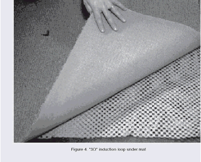
* The "3-D" loop developed by the Oval Window company has minimized the effect of spillover and telecoil orientation. In the 3-D loop, four wires configured in a prescribed geometric pattern are embedded in a mat placed beneath carpeting. Reportedly, the resulting electromagnetic signal is not only contained within the looped area, but the "3- D" pattern of the electromagnetic field reduces the impact of the telecoil orientation upon the perceived signal. A limitation of the 3-D IL system is that the listening area must permit the installation of one or more rugs (see figure 4).


User Comments/Questions
Add Comment/Question