2.1 Induction Loop (IL) Systems
2.1.1 General Description
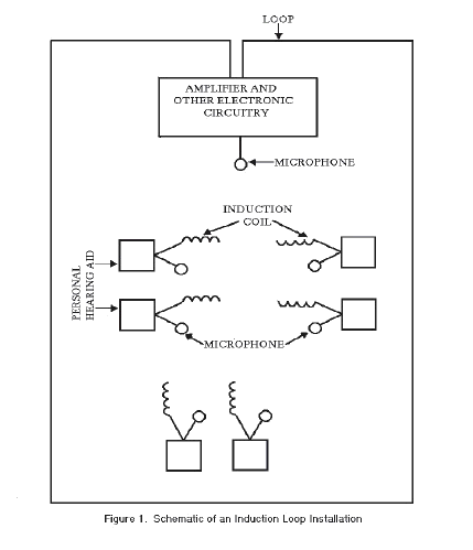
In an IL system, the output from an amplifier is delivered to a loop of wire placed around the circumference of a designated "listening area". The audio signals from the sound source (usually a microphone, though other audio sources can be accommodated) are amplified and sent as an alternating electric current through the wire loop. This electrical current creates an electromagnetic field around the wire. This electromagnetic field - basically the original audio signals coded in a different form - can be accessed by someone wearing a hearing aid (or special IL receiver) switched to the telecoil position. The telecoil is an "induction" coil, one in which an electrical current is "induced" when it is placed within the electromagnetic field. In other words, the information coded in the electromagnetic field is converted to an electrical current. This electrical current is then amplified by the hearing aid and converted back into audio signals. The sequence goes as follows: audio input > amplifier > electrical current in wire loop > electromagnetic field around wire loop > induced electrical current in telecoil > audio output (see figure 1).
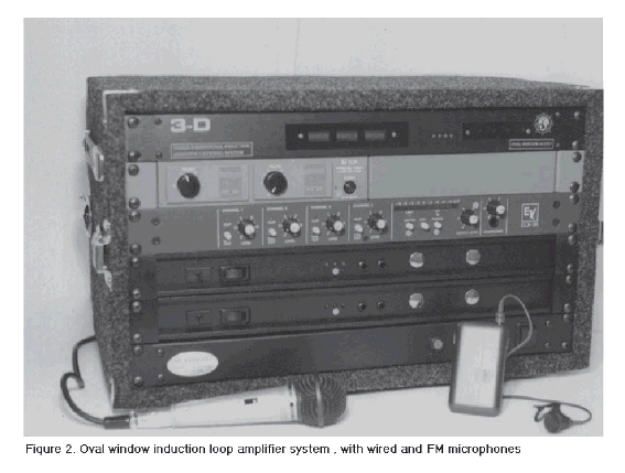
IL systems are the oldest - and least employed - of the existing ALS in this country (they are used much more often in European countries). The loop has to be physically placed around the listening area and secured so that it will stay in place. Once properly installed, and given that the listener's hearing aids include "T" coils, an IL system is undoubtedly the most convenient and possibly the most cost effective ALS. To hear the audio, all a person has to do is enter the looped area and switch his/her personal hearing aids to the telecoil position. As long as the person's hearing aids include "T" coils, he or she always has an assistive device "receiver" available. Wireless FM microphones can be integrated into the system and employed by talkers in order to provide instructional flexibility (see figure 2).
2.1.2 Standards
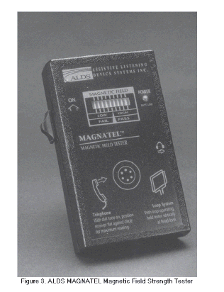
There are no national US standards that define the required performance of IL systems. The International Electrotechnical Commission (IEC) has developed pertinent standards for "Magnetic field strength in audio-frequency induction loops for hearing aid purposes" (IEC, 118‒4, l981). Suggested modifications to these standards have been made by Oval Window Audio, a manufacturer of audio loops in this country. Standards developed at the National Technical Institute for the Deaf (Johnstone l997) are part of the NTS Uniform Fire Prevention and Building Code, Chapter 23 of the Laws of l989 (Title 9, Subtitle S, Volume 9 Executive [B] of the "Official Compilation of the Codes, Rules and Regulations of the State of New York"). Each of these wil l be briefly reviewed. In ensuring that the prescribed magnetic field goals are achieved, the utilization of a "magnetic field-strength" meter is assumed (see figure 3).
2.1.2.1 Summary of IEC 118‒4 (1981) Standards
With a source of 1000 Hz equal to the long-time average level of the speech signal applied to the input of the system, the resulting field strength within the loop shall average 100 mA/meter +/- 3 dB. This level should not go below 70 mA/meter or above 140 mA/meter. These values apply to the vertical component of the field strength inside the area enclosed by the loop, measured 1.2 meters above the floor. Allowing for the 12 dB peaks occurring in speech signals, peak field strength may reach 400 mA/meter. The frequency response shall be 100 Hz - 5 kHz +/- 3 dB. The document includes a statement that in schools for hearing-impaired children it may be desirable to boost the low frequencies to compensate for the decrement in the low frequency response often produced by the inductive process. The degree of such a boost, and whether and under what circumstances it should take place, is therefore a local option.
2.1.2.2 Additional Proposed Specifications (by Oval Window Audio)
1. Loop Wire Installation: In order to maximize signal strength and uniformity, the loop wire shall be installed either at floor or ceiling level. At least 80% of the installed loop should be free of the influences of metal, either in front of, or immediately behind the wire.
2. Field Strength: As per IEC 118‒4, with the additional condition that the measurements be "A" weighted to disallow the influence of inaudible low frequency power line electrical noise.
3. Input Signal Compression: To compensate for fluctuating signal input levels, an automatic gain control, signal compression, and/or adjustable non-distorting peak limited must be employed at the input of the system (Recommended compression ratios: 4:1 for music, and up to 20:1 for speech).
4. Frequency Response: Frequency response measurements conducted with an "A" weighted field strength meter must be corrected to compensate for the substantial low frequency roll off characteristic of this weighting network.
5. Ambient Electrical Interference: Sources of electromagnetic radiation that may interfere with the proper functioning of an induction loop system include: faulty fluorescent lighting, light dimmers, electrical wiring, TV and computer monitors, surge protectors that are in close proximity to the loop system. An on-site evaluation of ambient electromagnetic noise should be performed before a loop is installed in order to identify and resolve electromagnetic interference. Ambient electromagnetic noise should not exceed 25 mA/meter or –12dB ("A" weighting) re: 100 mA/meter as measured at any seat within the looped area. If potential sources of noise cannot be reduced or eliminated, then the use of a loop must be ruled out.
6. Signal Spillover: When adjacent areas are equipped with an induction loop, signal spillover must not exceed 12.5 mA/meter, or –18 dB ("A" weighted) re: 100 mA/meter as measured at any location within an adjacent loop. Listening tests should also be performed to determine if signal spillover is audible.
7. System Signal-to-Noise: The electrical signal to noise ratio of the loop amplifier output (measured directly, not inductively) at 1000 HZ must be at least +30 dB at an output level sufficient to deliver mA/meter as per IEC 118‒4 specifications.
8. Distortion: With an input signal of 1000 Hz and the system adjusted for an output of 100 mA/meter, harmonic distortion must not exceed 3%.
2.1.2.3 New York State Standards
Ambient electro-magnetic fields should not exceed 30 mA/meter; higher levels would preclude the installation of an IL in the particular location. In the event that adjacent areas were to be looped, magnetic field "spill-over" should not exceed 15 mA/meter. Given a 1000 Hz signal at a level equal to the long-time average level of speech, the average value of the magnetic field should be 100 mA/meter +/- 3 dB between 100 to 8000 Hz, with a maximum no greater than 400 mA/meter. This same signal should produce no more than 5% harmonic distortion and provide a signal to noise (ambient magnetic field) of at least 30 dB.
2.1.3 Receivers
The major advantage of IL systems is that they permit listeners whose hearing aids incorporate telecoils to use their own hearing aids as the receiver. All the person has to do is enter the field and switch the hearing aids to the telecoil position. Given an appropriately functioning telecoil (see issues below), wearers have the advantage of being able to utilize their own hearing aids that, presumably, provide an appropriate and individualized amplified frequency response. There are headsets and pocket receivers available that will detect and amplify an IL signal, but this defeats the major advantage of IL systems - their convenience to the user.
2.1.4 Issues
* Only about 30 percent of modern hearing aids in the United States include a telecoil (more than twice this number use telecoils in Europe, which may help explain the popularity of IL systems there). As useful as telecoils are, with the trend toward smaller and smaller hearing aids, it seems unlikely that this 30% figure will increase in the future. Given the potential advantages of telecoils, not only for IL systems and telephones, but for all other types of ALS as well, it is unfortunate that a higher percentage of hearing aids do not routinely incorporate them. However, unless there is a drastic change in the type of hearing aids used by hard of hearing people, it does not appear that the use and popularity of IL systems will significantly increase.
* Even when a hearing aid includes a telecoil, it is quite likely that its electroacoustic performance will not duplicate the hearing aid's microphone response (Rodriguez, Holmes & Gerhardt l985; Culpepper l986; Thibodeau & Abrahamson l988). However, recent developments in hearing aids suggest that this variable can be circumvented, either by programming the telecoil to match the microphone response (Davidson & Noe l994) or by using amplified telecoils (Noe, Davidson & Mishler 1997).
* Complicating telecoil usage is its physical orientation within the hearing aid. For optimal sensitivity to an IL system, the telecoil should be mounted perpendicular to the floor loop (or a neckloop). But since optimal sensitivity for detecting the electromagnetic field around a telephone occurs when the "T" coil is in the horizontal position, a positional compromise is often necessary (Preves, l994).
* The newest telecoil standards (revision of ANSI S3.22) provide for measurements in which the extent of any compromise can be determined. In this new standard, the high frequency average (HFA) gain in the microphone position of the hearing aid is explicitly compared to both simulated telephone and induction coil usage (Preves 1996). The differences are expressed as Simulated Telephone Sensitivity (STS). A zero figure means that at the same gain control setting, the high frequency average gain in the microphone position was equal to that obtained in the telecoil position. Usually, the STS is negative, indicating that the gain must be increased in the telecoil position to achieve the same results as in the microphone position. Preves (l996) points out that the STS can be positive with the use of preamplified telecoils, and indeed this was found in the most recent study looking at ALS (Noe, Davidson & Mishler l998). However, it should be noted that even with an STS of zero there can still be significant differences in the frequency response between the telecoil and the microphone positions. That is, while equal high frequency average gain can be obtained at the microphone and telecoil positions, the pattern of gain may be quite different for the two conditions.
* The hearing aid microphone is usually disconnected when the telecoil is switched on. Since in some applications, it is desirable that the person be able to respond to audio signals (such as being able to hear side comments by one's partner during a lecture or stage performance), the optimal situation would be for the hearing aid to include an M/T position (both microphone and telecoil operative) and to do this without changing either the microphone or the telecoil frequency responses or output levels.
* The electromagnetic field is not confined within the looped area; some of the electromagnetic field "spills over" into adjacent vicinities. This is not a problem unless induction loops are also installed in the adjacent areas (vertical or horizontal), in which case listeners can be exposed to simultaneous audio signals from different sources. Also, the intensity of the signal within large looped areas can vary; the further from the wire, the weaker the signal. A great many creative loop configurations have been used in an attempt to circumvent these problems, with mixed results (Lederman & Hendricks l994).
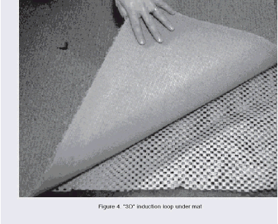
* The "3-D" loop developed by the Oval Window company has minimized the effect of spillover and telecoil orientation. In the 3-D loop, four wires configured in a prescribed geometric pattern are embedded in a mat placed beneath carpeting. Reportedly, the resulting electromagnetic signal is not only contained within the looped area, but the "3- D" pattern of the electromagnetic field reduces the impact of the telecoil orientation upon the perceived signal. A limitation of the 3-D IL system is that the listening area must permit the installation of one or more rugs (see figure 4).
User Comments/Questions
Add Comment/Question