4 - Best practices for construction observation
Construction observation is the final step in building an accessible element to meet design and regulatory requirements. Even though the final responsibility rests with the contractor, the architect, or other design professional should be observing construction and requiring the contractor to use the measurement protocols outlined in the specifications. For large projects for where extensive accessible surfaces are required, early checking should be done to suggest needed adjustments to construction techniques. The final check, of course, is with the regulatory agencies.
Suggested accessibility guidelines for exterior concrete surfaces
Current standards for ramps, sidewalks, and intersections and other concrete tolerances are given in ACI 117, Specification for Tolerances for Concrete Construction and materials and Commentary. The following tolerances may be applicable for exterior accessible surfaces. Other tolerances and measurement protocols are given using various methods but these are for interior surfaces.
-
For exterior ramps, sidewalks, and intersections, in any direction, the gap below a 10 - foot unleveled straightedge resting on highspots shall not exceed +1/4 inch (6 mm).
-
The tolerance for the top surface of a slab - on - ground is ± 3/4 inch (19 mm).
-
The deviation from slope or plane of formed surfaces over 10 feet (3 m) is ± 0.3% of length. This is approximately 3/8 inch in 10 feet (10 mm in 3 m). However, the ACI standards do not permit interpolation or extrapolation for dimension greater than or less than 10 feet.
-
The tolerance for deviation from slope or plane for a stair tread from the back to the nosing is ± ¼ in (6 mm).
-
The difference in the height of adjacent risers of stairs measured at the nosing shall not exceed 3/16 inch (5 mm).
If a more detailed method of specifying tolerances and measurement protocols are required the following are suggested. These suggestions are detailed enough to provide information necessary to determine if the surface is suitable for the majority of disabled users but simple enough to allow workers of various skill levels using basic tools to complete the necessary measurements for installations of all sizes.
1 Accessibility for walks, ramps, and stairs
1.1 Measurement protocols
1.1.1 Measurement tools. Distance measuring devices should be capable of measuring to a precision of 1/16 in. (1 mm). Angular or slope measuring devices should be capable of measuring to a precision of 0.1 degree and elevation measuring devices should be capable of measuring to a precision of 0.01 ft (1/8 in. or 3 mm).
For measuring device accuracy, the instrument and technique for measurement should provide for an accuracy of at least one - third the required tolerance. For tolerance measurement requirements of 1/8 in (3 mm) this would mean a device capable of measuring to about 3/64 in. Because this is not realistic in construction, a tape measure with 1/16 in. divisions is a reasonable compromise for inch - pound units. For metric measure, most tapes are marked in 1 mm units, which make them ideal for determining 3 mm tolerances.
If some tolerances are set at 0.5% slope (0.2865 degrees or approximately 0.3 degrees), then the accuracy of the instrument for measuring slope should be ±0.1 degree. Digital inclinometers (SmartTool®), floor profilers, and other electronic instruments are capable of measuring to this accuracy. 0.01 ft accuracy for elevations is common in surveying and nearly all instruments, including metal tapes, can achieve this accuracy.
1.1.2 Walks. Measure walks and other non - ramp pedestrian surfaces for overall running slope and cross slope as well as local running slope and cross slope variations (flatness) in accordance with 1.1.3, 1.1.4, 1.1.5, 1.1.6, and 1.1.7. This includes surfaces with a maximum slope of 1:20 (5%), such as a walk, parking area, or a portion of a driveway that is also used for a walking surface.
1.1.3 Walk running slope. Measure for overall running slope (the primary direction of travel) by determining elevations at the ends of the walk, noticeable changes in slope, or at a maximum of 20 ft (6 m) intervals beginning at one end of the walking surface. Elevations should be measured at the midpoint of the width of the walking surface. Calculate the slope using the horizontal distance between elevation points and the difference between the elevations at those points (i.e. the rise over the run).
1.1.4 Walk cross slope. Measure for overall cross slope (the direction perpendicular to the running slope) by establishing elevations at the outside edges of the walking surface at 10 ft (3 m) intervals beginning at one end of the walking surface. Calculate the cross slope at these locations using the horizontal walking surface width and difference between the measurement elevations at the edges of the walking surface (i.e. the rise over the run).
If an obvious change in cross slope occurs between measuring points (such as a steeper driveway crossing a sidewalk), measure a minimum of two cross slopes at the steeper portion, but in no case should the measurements be farther apart than 5 ft (1.5 m).
A simple method of establishing the relative elevations is to use a rotating laser level on a tripod and document the difference in height on a stiff metal tape measure or surveyor's rod. Alternately, a surveyor's transit or other electronic surveying tool may be used if it meets the accuracy requirements of 1.1.1. For walkways that are narrower than the length of a carpenter's level, the instrument may be placed level, resting on the high edge of the walk, and the distance from the level to the low edge of the walk may be measured to determine the difference in elevation.
The methods in 1.1.3 and 1.1.4 of establishing the running slope and cross slope is consistent with the requirements of ADA/ABA - AG, which limits the running slope and cross slope of walking surfaces to 1:20 and 1:48, respectively. Slopes greater than 1:20 are considered ramps and must conform to the requirements for ramps. Currently, these are the only ADA/ABA - AG standards related to running and cross slope that must be met.
In the draft guidelines for public rights - of - way (which are not yet final) an exception for slope is granted to sidewalks that follow the natural slope of the adjoining street or grade even though it may be steeper than 1:20.
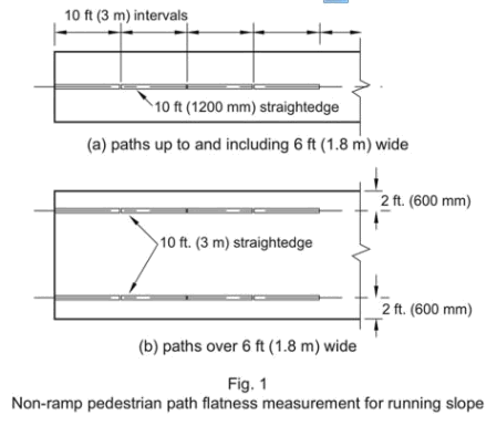
1.1.5 Flatness of walk running slope. For pedestrian paths up to and including 6 ft (1.8 m) wide, measure for flatness of the running slope at 10 ft (3 m) increments along the midpoint of the width of the walk by using a 10 ft (3 m) unleveled straightedge resting on high spots. Measure the distance between the straightedge and the surface at the largest gap. See Fig. 1(a). Alternately, electronic devices may be used that provide an equivalent 10 ft (3 m) flatness measurement.
For pedestrian paths over 6 ft (1.8 m) wide, measure for flatness of the running slope at 10 ft (3 m) increments along two paths, each 2 ft (600 mm) from the edge of the path. Using a 10 ft (3 m) straightedge resting on high points, measure at 10 ft (3 m) increments along the two lines. Measure the distance between the straightedge and the surface at the largest gap. See Fig. 1(b).
This method of measurement is consistent with the tolerance requirements of ACI 117 and can check for localized flatness. However, this section defines where the measurements should be taken.
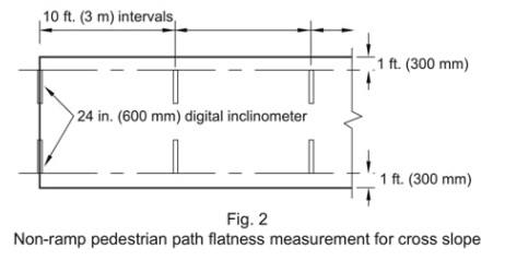
1.1.6 Flatness of walk cross slope. For walks and other pedestrian paths, measure flatness of the cross slope by placing a 24 - in. (600 mm) digital inclinometer perpendicular to the line of travel at 10 ft (3 m) intervals with not less than two measurements. Measure along two paths, each with the end of the digital inclinometer 1 ft (300 mm) from the edge of the path and placed toward the middle of the path. See Fig. 2. If the path is less than 6 ft (1.8 m) wide the ends of the measurement will overlap at each interval.
This method of measurement is based on the assumption that most accessible exterior walks will be at least 60 in. (1525 mm) wide due to passing requirements and that users will tend to stay toward one side or the other when traveling, approximately 1 ft (300 mm) from the edge. This method will reveal problematic variations in cross slope even though the overall cross slope may meet the 1:48 (2%) limitation.
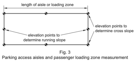
1.1.7 Measurement of parking areas. Only accessible access aisles and passenger loading zones that are part of a larger parking area need to be measured. These areas should be considered as a pedestrian walk with a minimum width of 60 in. and a length of approximately 20 ft and with an ADA/ABA - AG maximum slope of 1:48 in both directions. Overall running slope (in the long dimension) and cross slope (in the short direction) should be measured according to Section 1.1.3 and 1.1.4. This means that the overall slope in the long dimension should be measured along the center of the aisle or zone using the ends of the area as elevation measuring points and cross slope should be measured at each end of the area and at the midpoint of the area. See Fig. 3.
1.1.8 Alternate measurement tools. Walks may be measured with instruments other than a digital inclinometer if they provide the data required for evaluation of tolerances as given in Sections 1.2.1, 1.2.2, and 1.2.3. If the F - number system is used pedestrian paths should have a minimum FF of 25. Running slope should be measured along the same lines of measurements as given in Section 1.1.3.
Although the F - number system can be used to measure surface flatness for smooth surfaces it requires expensive equipment and workers trained to do the measurement.
An FF of 25 provides for a flatness of approximately ¼ in. in 10 feet (6 mm in 3050 mm). Waviness index may be a more appropriate measure to include if floor profilers are used.
1.1.9 Horizontal gaps and vertical alignment. Measure for local horizontal discontinuities and variations in vertical alignment such as at concrete joints, gaps, grade breaks, and at the interface of concrete with other materials or elements built into the surface. Measuring devices should be capable of measuring to a precision of 1/16 in. (1 mm).
Requiring a measuring precision of 1/16 in. (1 mm) allows measurements to be made to the nearest 1/8 in. (3 mm) without interpolation and allows the use of commonly available measuring tapes.
1.1.10 Ramps. Measure accessible ramps for overall running slope and cross slope as well as local running slope and cross slope variations (flatness) in accordance with Sections 1.1.11, 1.1.12, 1.1.13, and 1.1.14. Accessible ramps include curb ramps as well as other exterior ramps.
1.1.11 Ramp running slope. Measure for overall running slope of ramps by determining elevations at the top and bottom of the ramp at the midpoint of the width of each ramp run and calculate the slope using the horizontal ramp length and difference between top and bottom elevations (i.e. the rise over the run).
1.1.12 Ramp cross slope. Measure for overall cross slope of ramps by establishing elevations at the extreme edges of the ramp at the top and bottom of the ramp and calculate the cross slope at these two locations using the horizontal ramp width and difference between elevations at the edges of the ramp (i.e. the rise over the run). A simple method of establishing the relative elevations of the top and bottom of each ramp is to use a rotating laser level on a tripod and document the difference in height on a stiff metal tape measure or surveyor's rod.
This method of establishing the running slope and cross slope is consistent with the requirements of ADA/ABA - AG, which gives the standard for running slope and cross slope as 1:12 and 1:48, respectively. Currently, these are the only ADA/ABA - AG requirements related to running and cross slope that must be met.
1.1.13 Flatness of ramp running slope. Measure flatness in the running slope of ramps at 12 - in. (300 mm) increments by using successive, overlapping 24 - in. (600 mm) lengths using a 24 - in. digital inclinometer. For each measurement lay the instrument such that it reads the steepest slope or spans between two high points. See Fig. 4. Alternately, measurement can be made by using a digital inclinometer mounted on a 12 - in. (300 mm) beam or similar instrument with accuracy as stated in 1.1.1. Measuring 12 - in. (300 mm) lengths can account for local variations in slope that may be difficult for a person in a wheelchair or using other mobility aids to use.
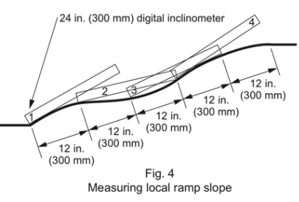
Measuring one - foot (300 mm) lengths allows for a reasonable check on local variation that can be accomplished easily and inexpensively with a 2 - ft digital inclinometer or other available instruments.
For ramps from 36 in. (915 mm) up to, and including, 5 ft (1525 mm) wide between handrails measure along two lines parallel to the length of the ramp. Each line should be approximately 6 in. (150 mm) from the inside (ramp side) edge of the handrail. For ramps where handrails are not used, such as curb ramps, measure 6 in. (150 mm) from the edge of the ramp. See Fig. 5(a).
For ramps over 5 ft (1525 mm) in width between handrails measure along an additional line for each additional 36 in. (915 mm) of width or fraction thereof beyond 5 ft (1525 mm). The additional line or lines should be spaced equidistant between the two outside measurement lines. See Fig. 5(b).
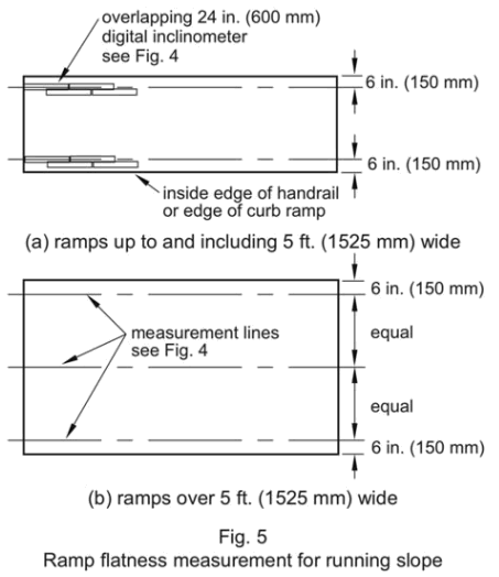
Measurement at 6 inches from the handrail or edge of curb ramps is approximately where the inside wheel of a wheelchair would be if the handrail is being used.
Requiring measurement along the running slope for every additional 36 inches means that measurements will always be taken to account for a distance between 24 inches and 42 inches. This is approximately where the path of a wheelchair or other mobility aids would be used without requiring excessive lines of measurement for wide ramps.
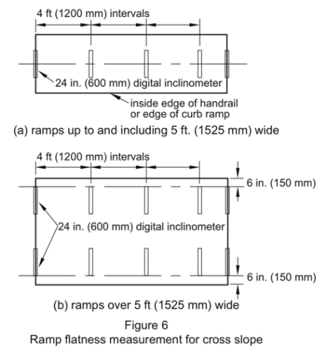
1.1.14 Flatness of ramp cross slope. For ramps, measure flatness of cross slope by placing a 24 - in. (600 mm) digital inclinometer perpendicular to the line of travel at 4 ft (1200 mm) intervals with not less than two measurements per ramp. For short ramps where only two measurements are made, measure cross slope at the top and bottom of the ramp. For ramps up to and including 5 ft (1525 mm) wide between the handrails, measure cross slope in the center of the ramp. See Fig. 6(a).
Because most exterior ramps will be 5 ft wide or less and the most common path of travel would be approximately in the middle of the path it seems reasonable to measure at the center of the ramp.
For ramps over 5 ft (1525 mm) wide between handrails, measure along both handrails with one end of the digital inclinometer placed at the line used to measure running slope. See Fig. 6(b). In addition to the measurement locations in 1.1.14, if a portion of the ramp appears to be steeper than 1:48 (approximately 2%) measure at that location as well.
As the ramp gets wider, users may tend to travel toward one side or the other, especially if the ramp is not a curb ramp and has handrails.
1.1.15 Flatness of ramp landings. Measure ramp landings at the midpoints of each landing in each direction using a 24 - in (600 mm) digital inclinometer. Edges of the ramp landing should coincide with the cross slope measurements as described in Section 1.1.12.
1.1.16 Alternate measurement tools. Ramps may be measured with instruments other than a digital inclinometer if they provide the data required for evaluation of tolerances as given in Sections 1.2.5, 1.2.6, and 1.2.7. If the F - number system is used ramps should have a minimum FF of 25. Measure running slope along the same lines of measurements as stated in Section 1.1.13
Although the F - number system can be used to measure surface flatness for smooth surfaces it requires expensive equipment and workers trained to do the measurement.
An FF of 25 provides for a flatness of approximately ¼ in. in 10 ft (6 mm in 3050 mm). Waviness index may be a more appropriate measure to include if floor profilers are used. The waviness index method is described in ASTM E 1486, Standard Test Method for Determining Floor Tolerances Using Waviness, Wheel Path and Levelness Criteria.
1.1.17 Stairs. Measure cast - in - place stairs for both riser height and tread depth of each riser and tread. For stairs 60 in. (1520 mm) or less in width, measure along a line approximately 18 in. (460 mm) from the wall or outside edge of the stair. For stairs with intermediate handrails take additional measurements approximately 15 in. (380 mm) on both sides of the intermediate handrail.
Measuring about 18 inches from the wall or edge of the stair places the measurement about where foot traffic is most likely.
Measure stair riser height as the vertical dimension between tread nosings. If a tread slopes for drainage, use a level or digital inclinometer to extend the line of the upper nosing to allow measurement to the nosing below.
This is consistent with the Life Safety Code method of measurement and reflects the position on a tread that a person's foot is most likely to contact, especially going down a stair. However, requiring the use of a level makes measurement more difficult and/or time consuming. If treads sloped uniformly for drainage, measurement could be made at the riser, from nosing to tread below because the measurement would be the same as using a level to measure from the back of the tread.
For exterior stairs sloped from the riser to the nosing for drainage, measure the slope of each tread using a digital inclinometer placed along a line as indicated in 1.1.17.
1.2 Suggested tolerances
1.2.1 Walks and other non - ramp surfaces. When overall running slope for walks is measured according to Section 1.1.3 a recommended tolerance for running slope is +1%. When overall cross slope for sidewalks is measured according to 1.1.4 a recommended tolerance for cross slope is +0.5%.
1.2.2 When flatness of running slope for an accessible surface other than a ramp is measured according to Section 1.1.5 no more than 20% (rounded to the nearest whole number) of the measurements should exceed ±1/4 in. in 10 ft (±6 mm in 3 m). When flatness of cross slope for an accessible surface other than a ramp is measured according to Section 1.1.6 at least 80% (rounded to the nearest whole number) of the measurements should not exceed a 2% slope. The remaining measurements should not exceed a 2.5% slope.
1.2.3 Landings. Both measurements of ramp landings as described in Section 1.1.15 should not exceed a plus tolerance of 0.5%.
1.2.4 When local horizontal discontinuities and vertical alignments are measured according to Section 1.1.9 a recommended tolerance is ±1/8 in. (3 mm).
1.2.5 Ramps. When overall running slope and cross slope for accessible ramps are measured according to Sections 1.1.11 a recommended tolerance for these slopes is +0.5%.
In the ideal case, planning for a 7.5% running slope allows for construction inaccuracies while still maintaining the required 1:12 slope. However, when a design slope of 1:12 is indicated a tolerance of +0.5% is reasonable.
Many accessibility experts consider a 2% cross slope to be the maximum. However, there is conflicting research concerning the need to have a 2% maximum cross slope and that the actual maximum depends on user type (wheelchair, walker, cane, etc.), length of travel, and other variables. It seems reasonable to allow a +0.5% tolerance for ramp slopes and cross slopes.
1.2.6 When local variations (flatness) in running slope of ramps are measured according to 1.1.13 at least 80% (rounded to the nearest whole number) of the measurements should not exceed an 8.3% slope. The remaining measurements should not exceed a 10% slope.
Allowing a small percentage of localized slopes to exceed 8.3% is based on the allowable slopes in ADA/ABA - AG (2004) for existing buildings of 1:8 (12.5%) for maximum rises of 3 inches and 1:10 (10%) for maximum rises of 6 inches. The 1980 ANSI A117 standard also allowed this with the additional provision that an existing ramp slope of up to 1:8 could have a maximum run of 2 feet (0.6 m). Allowing 20% of local variations to slope up to 10% seems reasonable for a distance of one foot. This would mean that localized dips and high points in a 2 - foot distance would be about ¼ in. (6 mm) or a little less.
1.2.7 When local variations (flatness) for cross slope of ramps are measured according to 1.1.14 at least 80% (rounded to the nearest whole number) should not exceed a 2% slope. The remaining measurements should not exceed a 2.5% cross slope. When four or fewer measurements are made, only one should not exceed a 2.5% cross slope, while the others should not exceed a 2% slope.
1.2.8 Exterior stairs, cast - in - place. When cast - in - place exterior stairs are measured according to Section 1.1.17 the requirements of the local building code shall govern tolerances.
User Comments/Questions
Add Comment/Question