Common Problems Arising in the Installation of Accessible Pedestrian Signals
This technical assistance guide is designed to provide information on common problems that arise in the installation of accessible pedestrian signals (APS). APS are most frequently provided at the request of a pedestrian who has a vision impairment. Current Federal Highway Administration (FHWA) policy requires State and local highway agencies to consider APS and to develop a "reasonable and consistent plan to facilitate safe street crossings" in existing developed rights-of-way. Chapter 4E.06 of the Manual on Uniform Traffic Control Devices (MUTCD 2003), adopted by State Departments of Transportation under the Federal-aid Highways Act, contains technical provisions for APS, where they are newly installed. The Access Board’s draft Public Rights-of-Way Accessibility Guidelines (draft PROWAG) includes APS provisions that have been harmonized with MUTCD. However, the Access Board has not yet finalized its rights-of-way rulemaking, nor has it been adopted as an enforceable standard by either the Department of Justice under Title II of the Americans with Disabilities Act or the Department of Transportation under Section 504 of the Rehabilitation Act of 1973.
June 2009
Prepared by:
Janet M. Barlow, COMS, Accessible Design for the Blind
AUTHOR'S CONTACT INFORMATION
Janet M. Barlow, COMS (Certified Orientation and Mobility Specialist)
Accessible Design for the Blind
3 Manila Street
Asheville, NC 28806
Phone: 770-317-0611
Email: jmbarlow@accessforblind.org

ACKNOWLEDGEMENTS
Photos in this paper are by the author, Lukas Franck, The Seeing Eye, Rafael Martinez, Martinez Engineering Group, Brett Rouillier, District of Columbia Department of Transportation, Dona Sauerburger, COMS, and Lois Thibault, US Access Board. Figures 2, 3, and 6 are from Accessible Pedestrian Signals: A Guide to Best Practice, developed for NCHRP Project 3-62.
SUMMARY
Incorrectly aligned or located APS devices provide ambiguous information in an environment in which few other cues may be available. Careful evaluation of every pedestrian signal installation is needed to assure that it meets the goals of providing accurate and helpful information to pedestrians who have vision impairments, particularly those who may also have hearing loss. Whether APS are installed at the request of a local resident or as part of a new pedestrian signalization scheme, they must function properly if they are to be useful in communicating the information provided to sighted pedestrians by visual pedestrian signals.
For more information, see resource material developed as part of the National Cooperative Highway Research Program Project 3-62: Guidelines for Accessible Pedestrian Signals at http://www.walkinginfo.org/aps/ or NCHRP Web OnlyDocument 117A.
Appendix
A checklist for evaluation of installations, adapted from Accessible Pedestrian Signals: A Guide to Best Practice, NCHRP Web Only Document 117A, is included here as Appendix A.
Introduction
Today’s wide and increasingly congested intersections and complex signalization schemes often fail to provide adequate non-visual information for crossing analysis and decisions by pedestrians who are blind or who have low vision. For the effective communication required by the Americans with Disabilities Act (ADA) of 1990, the WALK/DON’T WALK indications of visual pedestrian signal heads should be conveyed to pedestrians who don’t use visual cues. Accessible Pedestrian Signals (APS) provide this information through audible and vibrotactile indications.
Figure 1: Pushbutton-integrated APS (Polara)
The availability of improved technologies and the adoption of technical standards in the Manual on Uniform Traffic Control Devices (MUTCD) have led to significant increases in the number of APS installations over the past few years.
Chapter 4E.06 of the 2003 MUTCD, harmonized with the US Access Board’s draft Public Rights-of-Way Accessibility Guidelines (draft PROWAG), provides technical specifications for pushbutton-integrated APS with speakers and vibrating surfaces incorporated in the pedestrian pushbutton housing. These new APS deliver crossing indications to the waiting pedestrian at the departure curb rather than from overhead, as in older technology, and permit speaker volume to be set at a significantly lower and less obtrusive level. New tones -- ticks, clicks and other electronic sounds -- and speech messages replace the often-irritating ‘cuckoos’ and ‘chirps’ of yesterday. Tactile arrows and other features -- pushbutton locator tones, additional audible or Braille information, crosswalk maps, actuation indicators -- enhance the effectiveness of these new devices.
As with vehicular signals, APS should be installed, wired, coordinated, oriented, and adjusted so the information they provide about a street crossing is effectively communicated and reliable, so it will be safe in use. This requires the same careful attention to location and direction that is needed in the installation of traffic signals, with a particular focus on the sound and tactile features of the device in addition to visual features and timing attributes.
Researchers and orientation and mobility specialists who specialize in travel and street crossing skills1 report that some APS installations do not provide adequate accessible information for pedestrians who are blind or who have low vision. In the case studies that follow, some common problems are identified, and remedies recommended.
But first, a brief description of APS features and installation criteria:
1. To locate an orientation and mobility specialist, see http://aerbvi.org/modules.php?name=Content&pa=showpage&pid=4 for a list of chapters of the Association for the Education and Rehabilitation of the Blind and Visually-Impaired (AER).
Pushbutton-integrated APS
Figures 1 and 2 show several of the pushbutton-integrated APS devices that are available in the US. All include a pushbutton that is at least 50 mm (2 inches) in diameter, audible and vibrotactile WALK indications, a pushbutton locator tone, a tactile arrow, and automatic volume adjustment. Configuration, functioning, and adjustment methods vary somewhat by manufacturer. (See Interfacing Accessible Pedestrian Signals with Traffic Signal Control Equipment.)
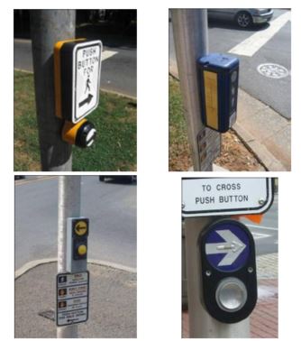
Figure 2: Examples of pushbutton-integrated APS from various manufacturers (left to right, Campbell, Prisma, Novax, Panich).
Location
Pushbutton-integrated APS rely on relative proximity to the crossing location, not on difference in sounds, to clarify which street crossing is being signaled. Proposed MUTCD revisions and draft PROWAG, supported by recent research2, specify that each APS device shall be installed on a separate pole. Devices must be located a minimum of 3m (10 feet) apart, no more than 3m (10 feet) maximum from the curb line (and closer, if possible), and between the curb ramp landing and the outside crosswalk line, or no more than 1.5m (5 feet) maximum from the outside crosswalk line. See Figures 3 and 4 for illustrations of pushbutton locations.
Figure 3: Optimal location of pushbutton-integrated APS - two pushbuttons on one corner, mounted on two separated poles – rapid tick WALK indication.
Source: NCHRP Web Only Document 117-A, Accessible Pedestrian Signals: A Guide to Best Practice, Figure 6-8
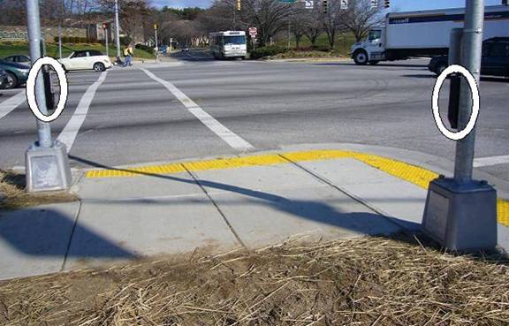
Figure 4: Installation of APS on two separated poles, aligned with crosswalk lines
(APS devices circled)
Devices that are located on existing mountings may not be able to provide optimal usability, particularly for the vibrotactile feature. APS should be located so pedestrians using the audible or vibrotactile indications can align and prepare for the crossing while standing close to the device AND the crossing departure point, and that pedestrians who use wheelchairs and scooters are able to reach the pedbutton from a flat, paved surface.
For graphics showing APS at corners with 10 foot and 30 foot radii and various types of curb ramps, see the curb ramp library, Chapter 6, in Special Report: Accessible Public Rights-of-Way – Planning and Designing for Alterations and examples in Figure 4E-3 of the draft MUTCD.
2. Scott, A.C., Myers, L., Barlow, J.M., and Bentzen, B.L. Accessible pedestrian signals: The effect of pushbutton location and audible WALK indications on pedestrian behavior. Transportation Research Record: Journal of the Transportation Research Board. 2005. Number 1939, pp 69-76.
Pushbutton locator tone
The pushbutton locator tone is a low-volume tick or tone that repeats constantly, at one-second intervals, during the flashing and steady DON’T WALK intervals to advise pedestrians of pushbutton availability and location. The 2003 MUTCD requires that locator tone volume be carefully adjusted to be audible a minimum of 1.8 m (6 feet) and a maximum of 3.7 m (12 feet) from the pushbutton, or to the building line, whichever is less. The pushbutton locator tone on a properly-installed pushbutton can also indicate the crossing location to an approaching pedestrian and may provide useful cues to an irregular crossing.
Audible WALK indications
Audible WALK indications are broadcast from a speaker that is incorporated into the pedestrian pushbutton housing. When the pedestrian pushbutton is properly located close to the departure curb, a low-volume WALK signal will be adequate for usability. Although most devices can also provide on-demand audible beaconing, the standard audible indication is not intended to be heard across the street. As with pushbutton locator tones, the 2003 MUTCD requires that the volume of the audible WALK indication be carefully adjusted to be heard a minimum of 1.8 m (6 feet) and a maximum of 3.7 m (12 feet) from the pushbutton, or to the building line, whichever is less.
Device technology automatically samples audible output and compares it to ambient sound, adjusting volume accordingly. Note that louder is not better -- an installation that is too loud may mask critical vehicle sounds and be difficult to localize and use for guidance.
Rapid tick WALK indication. Where pushbutton APS are located on separate poles, the recommended audible WALK indication is a fast ticking or beeping percussive sound at 8-10 repetitions per second. Research shows that using the same sound for both crossings results in more accurate and faster responses than two different sounds or speech messages if APS are separated and each is located close to the crossing it signals.3
Speech WALK indication. When two APS are mounted on the same pole, or are located closer than 10 feet to each other, using different tone indications (such as the cuckoo/chirp of older technology) provides ambiguous information that could result in a pedestrian crossing on the wrong signal.4 5 6 7 When two APS must be located closer than 10 feet apart in an alteration where it is infeasible to separate them, speech WALK indications and other features are needed to distinguish the crossings. If speech messages are used, the recommended WALK message is “[street name], WALK sign is on to cross [street name]. For example, “Peachtree, WALK sign is on to cross Peachtree, Peachtree, WALK sign is on to cross Peachtree”. This message is repeated for the duration of the WALK indication. Speech WALK indications should be accompanied by tactile arrows and Braille labels so that pedestrians who are blind can determine street names.8
3. Ashmead, D.H., Wall, R.S., Bentzen, B.L. and Barlow, J.M. Which Crosswalk? Effects of accessible pedestrian signal characteristics. ITE Journal. 2004. 74-9, pps 26-31.
4.Bentzen, B.L., Barlow, J.M., and Franck, L. Addressing barriers to blind pedestrians at signalized intersections. ITE Journal. 2000. 70-9, pps. 32-35.
5.Carroll, J. and Bentzen, B.L. American Council of the Blind survey of intersection accessibility. The Braille Forum, 1999. 38(7), pps. 11-15.
6.Uslan, M.M., Peck, A.F., and Waddell, W. Audible traffic signals: how useful are they? ITE Journal, 1988. 58, pps. 37-43.
7.Bentzen, B.L., Barlow, J.M., Franck, L. Speech messages for accessible pedestrian signals. ITE Journal. 2004. 74-9, pps 20-24.
8.MUTCD NPA contains specifications of features required with speech messages in 4E.09. Federal Register Volume 73, Number 1, pages 312-313, January 2, 2008.
Vibrotactile WALK indications
Vibrotactile indications are transmitted by a vibrating plate or arrow on the housing of the pedestrian pushbutton. During WALK, the arrow or plate vibrates. Thus, a pedestrian must be able to stand with a hand on the device while he/she is aligned and waiting to begin crossing. The vibrotactile indication is particularly useful for pedestrians who have both hearing and visual impairments and also allows pedestrians to tactually confirm audible signal information in noisy environments.
Tactile arrow
The tactile arrow on the device must be aligned with the direction of travel on the crosswalk and point toward the street crossing that the pushbutton controls and signals. For most devices, this requires aligning the face of the device and pushbutton with the crosswalk lines. This takes care in installation, particularly when drilling mounting holes for the device.
Other Features
Most pushbutton-integrated APS can provide additional features. These may include Braille labels for street names, actuation indicators (a light or beep), tactile crosswalk maps, and options activated by an extended button push: audible beaconing (useful for directional guidance at irregular or long crossings), extended pedestrian timing, and recorded information of street names or additional information about the intersection.
For further information, see NCHRP Web-only Document 117A, Accessible Pedestrian Signals: A Guide to Best Practice, available online.
Installation Issues
Issue 1. APS volume (louder is not better)
Issue 2. Location, location, location
Issue 3. Which signal? Speech indications necessary
Issue 4. Wrong pole …Wrong message
Issue 5. Tactile arrow (In-line)
Issue 6. Pre-timed installations (an APS is more than a pushbutton)
Issue 7. Repair/replacement (put it back right!)
Issue 8. Rest-in-WALK installations (quiet time OK)
Issue 9. Reach (how far?)
Issue 10. Braille (right side up!)
Issue 11. Good vibrations (vibrotactile indications)
Issue 12. Audible beaconing
Issue 13. Stub poles
Issue 14. Inspection (beware of field changes)
Issue 15. Installation errors increase risk
Issue 1: APS volume
Louder is NOT better. It is common to find APS volumes set so loud that the pushbutton locator tone and audible walk indication can be heard at midblock or across the street -- or in a quiet office or bedroom nearby. This can lead to neighborhood as well as user concerns, since excessive volume will mask other sounds that are important to pedestrians who are blind (such as the sound of traffic surges or the indication of another APS on the same corner).
An APS signal should be audible at the beginning of the crosswalk, but no more than 3.7 m (12 ft) from the pushbutton, or to the building line, whichever is closer (2003 MUTCD). Technologies that broadcast from above require higher- volume settings to be effective, and often are labeled neighborhood nuisances. Modern pushbutton-integrated devices provide the signal right where it is needed -– at the departure curb –- so it needs to provide only a 2-5 dB gain over ambient noise to signal the pedestrian interval. Click or tick tones are less apt to annoy and are more detectable in traffic noise than the older cuckoo/chirp outputs.9 They are also less likely to be confused with a bird.10 11
Remedy: When APS noise annoys, reduce the signal volume. Volume adjustments differ by manufacturer: some devices can be set through a hand-held PDA, while others require adjusting set screws on a control board mounted in the pedestrian signal head. APS volume should be set individually at every location. Note that nearby building facades or other hard surfaces that reflect the APS signal may actually cause the APS to increase in volume in reaction to its own sound, if the sound or ambient sound response is set too loud. Sound baffles may also be necessary in some locations. It’s important to adjust the APS and listen carefully. For particularly difficult situations with very near neighbors or nearby hard reflective surfaces, consider a change in sound type from a beep to a tick or click, which may be less annoying to listeners.
In most devices, the pushbutton locator tone volume and the WALK indication volume are set separately, and each has a minimum/maximum range. If there is a lot of traffic noise at some times of the day, the maximum volume of both the pushbutton locator tone and the WALK indication may need to be relatively loud, near 90 dB. However, the minimum volumes could be set in the 30 – 40 dB range to avoid annoyance at night, or when traffic volumes and ambient sound levels are low.
The response-to-ambient sound operates in conjunction with the volume settings, but is usually set separately. If the ambient sound adjustment is set to respond at 15 dB over ambient, APS are likely to be too loud when there is noise at the intersection, even if volume is appropriate for times when the intersection is quiet. The 2003 MUTCD specifies a sound volume at least 2, but no more than 5, dB over ambient.
The installer or an assistant should walk approximately 10 feet away from the device and listen to its volume during fluctuations in traffic before finalizing the volume adjustments. The installer should also listen from a distance of approximately 30 feet away. If adjusting an APS requires opening the pedestrian signal head to get to the control board to make the sound adjustments, the pedhead should be closed, and all reflective materials, such as ladders, should be moved away before this ‘final listen.’
9. Wall, R.S., D.H. Ashmead, B.L. Bentzen, & J. Barlow. Directional guidance from audible pedestrian signals for street crossing. Ergonomics. 2004. Vol. 47, (12), 1318 – 1338.
10. Carroll & Bentzen. p. 14.
11. Bentzen, Barlow & Franck, 2000, p 34.
Issue 2: Location relative to the crosswalk
An APS that is mounted outside the crosswalk area may provide misleading information about the crossing location. Pedestrians who are blind may stand beside the pushbutton while waiting to cross, particularly if they use the vibrotactile indication.
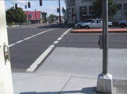
Figure 5: APS is located about 8 feet from the crosswalk and curb ramp landing.
In the situation pictured in Figure 5, pedestrians who begin their crossing beside the pushbutton would be outside the crosswalk lines and may not be anticipated by turning drivers.
If the pedestrian who is blind also encounters the median island and stops, there is no APS or pushbutton on the median to call a WALK to complete the second half of the crossing. Since the APS is not close to the crosswalk and curb ramp, the volume of the audible walk indication and pushbutton locator tone must also be louder in order to be heard from the crossing location.
Remedy: One solution is to move the pole closer to the crosswalk lines, so the device is in reach of the landing of the curb ramp and adjacent to the crosswalk. This will assist pedestrians who are blind in finding the APS pushbutton and in beginning crossing from within the crosswalk area.
In existing streetscapes, without a median, it may also be possible to widen the crosswalk (and adjust the stop line accordingly) to eliminate the offset.
Vehicular signal poles are rarely in optimal position for mounting APS pushbuttons. A better choice is to provide an individual stub pole or pedestrian signal pole at the top of every curb ramp. Where the sidewalk is separated from the curb, use a returned curb rather than a flare at the ramp (good for wayfinding, if properly aligned) and locate the stub pole within the border adjacent to the landing at the top of the ramp. For recommended pedestrian pushbutton locations at a variety of ramp types, see Chapter 6 in Special Report: Accessible Public Rights-of-Way, Planning and Designing for Alterations, which was developed by a subcommittee of the Public Rights-of-Way Access Advisory Committee (PROWAAC).
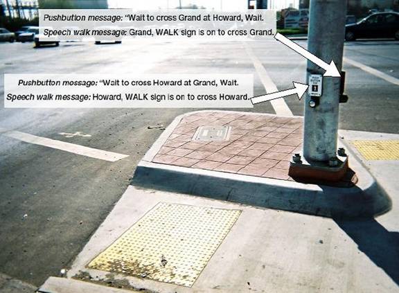
Issue 3: Which signal? Speech WALK messages necessary
In numerous installations evaluated in the field, where two APS were mounted on the same pole, installers failed to customize the messages and used the manufacturer’s default message, ‘WALK sign is on’. With two APS located closer than five feet to each other, it is impossible to distinguish which one is sounding based on the location and direction of the sound. Pedestrians standing at one crosswalk could mistake the message of the other crosswalk for their indication to begin crossing.
Remedy: If possible, move the APS to separated poles, each close to the crosswalk it controls and indicates (see Figures 3 & 4).
In Figure 6, it appears that the required APS separation (10 feet minimum) could have been achieved here by locating stub poles to the left side of the left ramp and the right side of the top crossing. That would have provided much less ambiguous information for pedestrians using these crossings. While a common pole can be made to work, it should not be the selected solution where separated poles are possible.
Mounting two pushbuttons on the same pole will require ordering and installing -- in the proper device! -- custom speech chips for both the WALK message and the pushbutton information message to identify, by name, the street that the device controls. Some manufacturers provide equipment so jurisdictions can record their own messages. If used, care must be taken in recording messages with proper wording and clear speech.
Speech messages should include the street name and use this tested format: ‘Howard. WALK sign is on to cross Howard’. A pushbutton information message (activated by an extended button push) must say: ‘WAIT to cross Howard at Grand. WAIT.’ (See Figure 6). In addition, the APS should include Braille street name identification and a tactile arrow, carefully aimed to be in line with the crosswalk lines.12
12. MUTCD NPA contains specifications of features required with speech messages in 4E.09. Federal Register Volume 73, Number 1, pages 312-313, January 2, 2008.
Issue 4: Wrong pole! …Wrong message!
In Figure 7, APS have been installed on the wrong poles. The APS on the pole in the left of the photo has an arrow pointing toward the street on the right in the photo. Since the APS is closer to the departure curb and curb ramp for crossing straight ahead (in line with the photographer’s direction of travel), a pedestrian hearing the sound from that APS would expect that the APS governs that crossing, and may not even be able to hear the further distant APS that is actually for the crossing he/she intends (in the foreground of Figure 7).
Figure 7: Installation where APS are installed in wrong locations; both are too far from street they control and will be heard as closer to the other street.
Figure 8: Installation where APS are installed in correct locations in relation to crosswalks.
Remedy: Each APS should have been installed on the pole closest to the crosswalk it controls, as shown in Figure 8 (pushbutton for street on right is on the back side of the pole, out of view from photographer’s angle). For example, the APS for the crossing on the right in Figure 7 should be installed on the pole near the right side of the photo, and on the side of the pole toward the curb ramp, but still reachable from the level sidewalk. This will allow pedestrians to push the button and then hear the APS at the crosswalk departure point. The APS on the pole to the left in Figure 7 should be installed parallel to the crosswalk that it controls (the one straight ahead in the photographer’s view).
It may be possible to realign the APS on each pole and reconnect the wiring. However, APS can be wired to a control board in the pedestrian signal head or through the controller, so it may be necessary to move the pedestrian signal head (or to completely rewire each APS) to conform. The wiring and device output needs to be checked after modification to assure that the APS is signaling the correct crossing phase.
If the APS has a speech message, the APS needs to be moved to the pole closer to the crosswalk it signals, which will also require reversing the arrow and signs on the APS housing. If speech WALK messages or pushbutton information messages are installed, the functioning and accuracy of both should be checked after re-installation of APS devices.
Installation of the APS on a stub pole or separate pedestrian signal pole, as shown in Figure 8, rather than on a mast arm pole, is likely to provide better placement.
Issue 5: Tactile arrow (in line)
Figure 9: Tactile arrow not aligned with crosswalk direction.
Figure 10: Location where tactile arrow is aligned with direction of travel on the crosswalk.
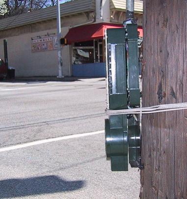
Figure 11: APS that was damaged in a crash and temporarily reinstalled with wire.
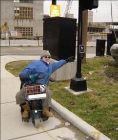
Figure 12: In this new construction, APS is located too far from the sidewalk to be reached by a user of a wheelchair or scooter.
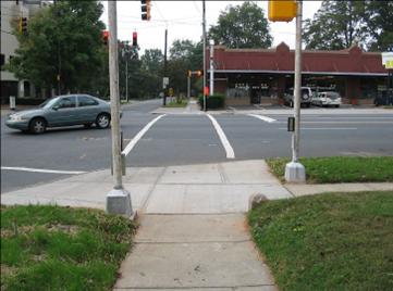
Figure 13: APS installed on poles in the landscape strip, and still within reach from a level paved sidewalk surface.
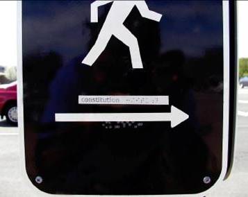
Figure 14: Braille sign installed backwards, with manufacturers’ label showing. Label includes street name and print of how Braille should look. Braille beneath arrow is backwards version of the print version shown on label and is indented, rather than raised.
Misleading wayfinding information will be conveyed if the tactile arrow is oriented toward the center of the intersection, rather than parallel to the crosswalk. In the photo below (Figure 9), the arrow is out of alignment with the crosswalk direction. Even small misalignments can inadvertently direct a blind pedestrian outside the crosswalk area or into the parallel traffic.
Remedy: The APS needs to be removed and reinstalled. The arrow must be aligned with the direction of travel on the crosswalk (2003 MUTCD).
Since the tactile arrow is on the face of the device or on the pushbutton, the APS mounting affects arrow alignment. If the needed adjustment is minor, it may be possible to shim behind one side of the device to align the arrow with the crosswalk. In other cases, it may be necessary to drill new mounting holes and reposition the APS on the pole. The arrow should be aligned as shown in Figure 10.
Issue 6: Pre-timed signals (an APS is more than a pushbutton)
Since pedestrians don’t need to use the pushbutton to get a WALK signal at pre-timed signals or where pedestrian signals are on recall, some transportation professionals have concerns and questions about installation of pushbutton-integrated APS at those locations.
The pushbutton locator tone in a pushbutton-integrated APS provides access to other information provided by the APS unit: the vibrotactile WALK; the tactile arrow for wayfinding; tactile mapping; if provided, and messages and actions available with an extended button push, such as audible beaconing or an extended crossing time. Thus pushbutton-integrated APS should be installed at pre-timed locations even if it is not necessary to use the pushbutton to call the WALK.
Some pedestrians may push the pushbutton when it is unnecessary, but that is not really a problem if the pushbutton is beside the crossing departure location. Regular intersection users will come to understand that they don’t have to push the pushbutton. If the actuation light is lit when the call is made, pedestrians who can see the actuation indicator will be able to recognize that the pedestrian call has already been made.
Remedy: Pushbutton-integrated APS are typically wired to the pedestrian signal and function as the pedestrian signal functions. APS, in typical operation, provide relatively quiet sounds from a location beside the crosswalk. Previous concerns about APS at pre-timed locations in downtown areas mainly stemmed from too-loud signals mounted on pedestrian signal heads, which echoed off buildings.
Issue 7: Repair/replacement (put it back right!)
An APS that was knocked down in a crash was reinstalled by workers who did not know how the device was supposed to function. After reinstallation, the APS was turned 90 degrees from its prior placement, and the tactile arrow was no longer pointing at the street the pushbutton controlled. The WALK message was provided at the wrong time for the street toward which the arrow pointed.
In another situation, shown in Figure 11, the APS was temporarily reinstalled, still functioning, but oriented incorrectly. It was several weeks before a crew reinstalled it properly. Meanwhile it provided inaccurate information. When the APS is not correctly installed, there is a risk that a person who is blind will cross a street with the wrong WALK indication or in the wrong direction.
Remedy: All maintenance personnel need to know enough about APS installations to recognize an APS, and to either call someone to check details of reinstallation, or to correctly re-install the APS themselves. Training is needed to avoid dangerous errors in reinstallation or repair.
Issue 8: Rest-in-WALK (quiet time ok)
In some locations, the pedestrian signals ‘rest-in-WALK’ and it may not be desirable to have the WALK indication repeat constantly during the long walk interval, because the WALK indication is a more constant sound than the locator tone.
Remedy: Draft PROWAG and proposed MUTCD language provides specific exceptions for ‘rest-in-walk’ situations.The audible WALK indication can be set to sound during the first seven seconds of the walk interval only and then revert to the locator tone. If someone presses the pushbutton during the walk interval, the WALK message can be set to sound again for seven seconds, or as long as the remaining time in the WALK, whichever is less. The vibrotactile indication usually vibrates during the entire walk interval.
When ordering APS for use in rest-in-WALK locations, or where pedestrian signal is on recall with long walk intervals, designers should check that the manufacturer offers options for rest-in-WALK settings.
Issue 9: Reach (how far?)
APS devices can be located in landscaped areas if the pushbutton is reachable from a level paved area. Figure 12 shows a location where new APS (and new sidewalks) were installed, but the APS are not usable. Besides the inaccessibility for wheelchair users, a person who is blind will have difficulty finding and getting to the pushbutton, even with the pushbutton locator tone sounding.
Remedy: Installation in landscaped areas must be carefully planned and monitored for accessibility. APS should be within the reach range (1.2 m/48 inches vertically, .25m/10 inches horizontally) for an individual who uses a wheelchair (draft PROWAG, R404). The APS shown in Figure 13 are appropriately located within the landscape strip, reachable from a paved level surface, and aligned with the crosswalk lines.
Issue 10: Braille (right side up?)
Where the APS device includes the street name in Braille, care must be taken to install the signs in the correct location and orientation.
Manufacturers usually impress the Braille into a standard metal sign attached to the APS housing. The typical sign includes print arrows and pedestrian symbols, often on both sides of the sign so that it can be flipped over to be installed on either side of the street. However, when Braille is added, the sign can no longer be reversed. Flipping the sign results in indented and backwards Braille symbols, which are unreadable.
Remedy: Braille is made up of small dots in a grid which are raised on the surface to be read by fingertip. Contractors and installers need to know that the Braille dots should be raised and should check all labels and instructions carefully.
Manufacturers may provide a paper tape label, showing the street name in print and in Braille, on the back side of the sign. The print label is not intended to be visible after the sign is mounted on the pole. In Figure 14, the label can be seen on the outside of the device. Careful inspection reveals that the actual Braille (below the arrow) is indented and all symbols are reversed from those shown on the label. This is not readable by touch! Braille dots must be raised, not indented.
A person who reads Braille could be asked to assist in checking the labels after installations. If the installation agency is not in contact with someone who reads Braille, individuals may be located through vocational rehabilitation agencies, schools for the blind, special education departments of public schools, or consumer groups.13
13. There are two major consumer groups of individuals who are blind, the American Council of the Blind, www.acb.org, and the National Federation of the Blind, www.nfb.org, with chapters in many US cities.
Issue 11: Good vibrations (vibrotactile indications)
APS device usability is compromised if the vibrotactile indicator doesn’t vibrate during the WALK. The vibrotactile indication provides WALK signal information for pedestrians who are both visually and hearing impaired and also may be used by pedestrians who are visually impaired (with normal hearing) to clarify or confirm which street’s audible WALK is sounding.
Where mounting two APS on one pole can’t be avoided, take care to ensure that the activation of the vibration of one device doesn’t cause vibration of the device for the perpendicular crossing.
Remedy: The functioning of the vibrotactile indication needs to be carefully checked before installation is considered complete and should be a part of regular maintenance checks.
Troubleshooting: If the arrow does not vibrate during WALK, there are several potential areas to check:
- the basic settings of the device;
- wiring to the vibrotactile feature; and
- attachment of the arrow to the device.
The vibrotactile indication can be turned off in some devices by a setting either on the control board or within the PDA device. Check settings to be sure vibration is on. Vibrotactile indications may have separate wires to attach in order to enable the feature. If those wires are not attached properly, or are attached to the wrong places, or are pinched when reclosing the device, the arrow may not vibrate properly.
If the plate holding the arrow is screwed in, over-tightening the screws can prevent the vibration. If the arrow is attached with glue, as found on some manufacturers’ APS, too much glue under the arrow can prevent the vibration of the arrow. The arrow needs to be glued down, but it also needs to contact the vibrating plate. It seems to work best to put a thin layer of glue around the outside edges of the recess, then insert the arrow and align it with the direction of travel on the crossing the device indicates.
If the arrow seems to be vibrating during flashing or steady don’t walk and there are two devices on the same pole, the devices are probably touching each other and causing vibrations. Installing insulation between the pole and the APS and between the two APS will probably remedy the problem.
Issue 12: Audible beaconing
Audible beaconing -- providing a louder audible WALK signal in order to provide directional guidance to pedestrians who are blind -- is not needed at all intersections or during every pedestrian phase. If installed at inappropriate locations, or incorrectly adjusted, audible beaconing can provide confusing or even dangerous information.
In the pedhead-mounted APS models installed in the US over the past 30 years, sounds were broadcast simultaneously from overhead speakers at each end of the crosswalk and at two parallel crosswalks at an intersection. Research now shows that pedestrians are not able to use the signal for directional information.14
Even with today’s newer technologies, audible beaconing (or a too-loud signal volume) from an APS at a ‘porkchop’ island with a channelized right turn lane may lead a pedestrian who is blind to cross the channelized turn lane, thinking it is signalized after hearing the audible WALK indication. And at locations where two parallel crosswalks are timed separately, such as locations with split phasing, a loud signal can lead a pedestrian to begin crossing with the wrong crossing indication.
Remedy: New types of APS allow calling a louder signal by holding the pushbutton in for more than one second, so audible beaconing is a feature that can be called ‘on request’. This allows a pedestrian who is blind to decide when a louder signal might be helpful and limits the impact of sound on the neighborhood.
Proposed MUTCD has recommendations for audible beaconing in section 4E.06.
Recent research has shown that a louder locator tone during the flashing DON’T WALK, from a speaker at the opposite end of the crosswalk from the pushbutton where audible beaconing was requested, improves performance in ‘ending within the crosswalk.’15
14. Wall, et al., 2004.
15. Scott, A.C., Barlow, J. M., Bentzen, B.L., Bond, T. and Gubbe, D. (in press) Accessible Pedestrian Signals at complex intersections: Effects on blind pedestrians. Transportation Research Record: Journal of the Transportation Research Board. 2008.
Issue 13: Stub poles
Figure 15: APS is located on mast arm pole more than 10 feet outside the crosswalk lines. In addition, a fire hydrant is between the crosswalk location (and the curb ramp) and the APS.
Figure 16: Stub pole was installed to locate APS near the crosswalk.
By installing APS on existing poles without careful evaluation of usability and function, jurisdictions may be obviating the benefits such devices provide. In the location shown in Figure 15 (a pre-timed intersection), the APS was installed on the available mast arm pole, resulting in an installation in which the APS volume had to be set to be quite loud in order to be heard at the crosswalk and where using the tactile arrow and vibrotactile WALK indication could result in a hazardous crossing.
In addition, the street names are similar -- Penn and Tenth -- and it is quite difficult to discern which is being announced in the speech WALK message, particularly at the crosswalk for crossing Tenth (the street to the left in Figure 15), where the APS is too far from the street.
Remedy: In a similar location, shown in Figure 16, a stub pole was installed within five feet of the crosswalk in order to place the APS in a usable location. A signal pull box was already in the sidewalk area near the new stub pole location, so concrete work was minimized. Stub poles are commonly used in some jurisdictions.
Requirements for wiring and for mounting poles vary in different areas of the country. Flexibility in requirements may make it easier to install usable facilities for pedestrians.
Some examples of stub pole installations across the US:
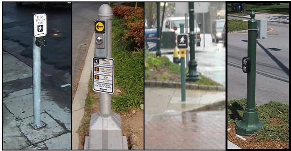
Figure 17: Examples of stub poles – different materials and installation.
Issue 14: Inspection of contractor’s work - Beware of field changes!
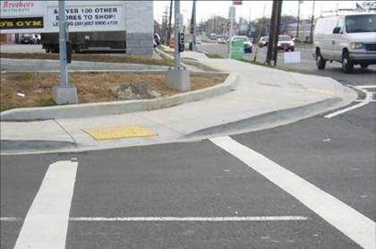
Figure 18: APS and curb ramps that were not installed as designed.
Figure 19: Another view of the same corner. Note shifting slopes and cross slopes on the ramps in addition to poor APS location.
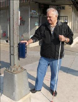
Figure 20: Deaf-blind user stands with his hand on the original APS to feel the vibration in order to know when to begin to cross.
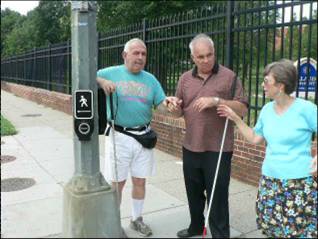
Figure 21: Orientation and mobility specialist explains the APS to two individuals who will be crossing there (two APS on same pole). One crossing is a few feet to the left of the photo; the other is approximately 20 feet to the right, straight ahead of individual standing with his arm on top of the APS.
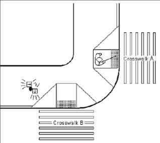
Figure 22: When two APS are mounted on an existing signal pole, one is poorly located. The pushbutton for crosswalk B is near the crosswalk, but the pushbutton (and vibrotactile arrow) for crosswalk A is a long way from the crosswalk.
While design drawings showed level landings and APS beside the level landings and crosswalks, the finished construction did not match the plans. At the location shown in Figures 18 and 19, the contractor made some decisions in the field that affected the usability of the APS and the curb ramps.
The APS to cross the street that is on the right in Figure 18 is not located according to the plans and the arrow points to the curb ramp, rather than being aligned with the direction of travel on the crosswalk. The poor location is more easily seen in Figure 19, taken from across the street. A red circle highlights where the pedestrian signal pole was supposed to be installed.
By the time the designer saw the installation, however, and noted the lack of compliance with specifications and with ADA requirements, the inspector had signed off on the job. The contractor and inspector both need to understand APS installation and use before making decisions in the field about revisions to plans.
Issue 15: Installation Errors Increase Risk
This account shows clearly why it’s critical for installers to understand how APS work and something about how pedestrians use them -- particularly when the APS is installed in response to a user request.
Some years ago, a city highway agency was contacted by a pedestrian who requested that an APS be installed at an intersection he crossed twice a day, going to and from work. He was a colleague of a local orientation and mobility instructor, who emphasized the urgency of the need in follow-up communications with the DOT, as one of the streets was a busy arterial.
After a lengthy wait, APS were installed for all crosswalks of the intersection. On one corner, the APS were installed on the wrong poles (as discussed in Issue 4) and the tactile arrows had also not been installed, but the orientation and mobility specialist explained to the user which buttons were intended for which crosswalk, and he was able to use them satisfactorily. However, after a few months he began complaining that the APS were no longer working. Technicians checked the devices more than once and didn’t find any problems.
Eventually, the pedestrian and the DOT signal technicians arranged to meet at the site. Demonstrating the APS, the technician said: “See? The button ticks so you know it’s there. When you press the button, the light comes on to let you know that it’s working. When the WALK signal begins, you hear a fast ticking sound”. After the interpreter signed that information in the pedestrian’s palm, the user shook his head sadly and signed back: “I am 100% deaf. I am 100% blind. I need the signal to vibrate.” The vibrotactile feature on the APS was not working and the technicians hadn’t noticed. (See figure 20).
After several more attempts to correct the installation and many months of delay that led to the filing of an ADA complaint against the agency, the DOT’s ADA coordinator reported that a replacement APS from a different manufacturer had been ordered and installed.
When the ADA coordinator went to check the installation, however, he realized that the APS on one corner of the intersection, while installed on two separated poles, were still installed on the wrong poles (see Issue #4). He had the mistake corrected; each APS was moved and reoriented on the pole close to the crosswalk it controlled. At a subsequent meeting with the deaf-blind user and the orientation and mobility specialist at the intersection, the pedestrian demonstrated how he used the APS. Using the now ‘wrong’ pedestrian pushbutton, he prepared to start his crossing … but no one had told him that the APS had been switched to the correct poles. Before he could step into the street, he was stopped, and the change of the APS was explained to him. He paused, stepped back and looked dismayed, and then signed: “If you switch them again, please inform me!”
On the other corner, APS for the two different crossings were both installed on one pole, as shown in figure 21 and 22. The distance to the crossing (on crosswalk A) results in other problems. While there, it was noted that the Flashing Don’t Walk (FDW) signal also was extremely short – so short (3 seconds) that it was possible for a pedestrian to leave the pushbutton and prepare to cross the street while the vibrotactile indication was still active, but step into the street after the FDW had ended.
This timing issue is complicated by the fact that the pedestrian pushbutton for THIS crossing is well over 10 feet from the street (see figures 21 and 22). It takes this deaf-blind pedestrian nine seconds to get to the crosswalk after detecting the vibrotactile signal. After he arrives at the departure curb, it takes him 18 more seconds to complete the crossing.
Because the FDW is much shorter than the pedestrian needs for crossing, he cannot be confident of having enough time to cross unless he waits to start until the beginning of the WALK vibration, which causes him unnecessary delay. For this individual and APS location, the pedestrian clearance time should be set at 27 seconds. While signal timing here meets MUTCD minimums, the engineering of an accommodation like this, installed in response to a request, must be based upon individual use (Title II of the ADA requires that jurisdictions alter policies, practices and procedures when necessary for accessibility.16) To complete an effective accommodation for this pedestrian, a stub pole should be installed at the second crosswalk, so the two APS can be separated and each APS will be located close to the crosswalk it controls.
Another confusing complication here is that while the visual pedestrian signal comes on for each cycle, and the APS vibration for crossing the street from one direction comes on for each cycle, the APS vibration for the same crosswalk from the other direction comes up only in response to a pedestrian call (button press). This requires the pedestrian to use different strategies in timing of his button press at each corner, or he might start his crossing too late in the phase. At the corner where the vibration comes on with each cycle, he crosses at the beginning of the vibration. At the APS which requires a button press, if it starts to vibrate when he presses it, he needs to wait until the next cycle, because it could begin vibrating halfway through the walk interval. He must wait until it finishes vibrating, then press it again and start to cross as soon as it starts to vibrate for the second time in order to be sure he has enough time to cross. This inconsistency is the result of a simple incorrect setting in the APS, which needs to be changed so that the APS on each end of the crosswalk work in the same manner.
Small details can add up to big differences in the usability – and safety! -- of APS devices. The jurisdiction is still working on correcting the problems, more than 6 years after the APS were first requested. Meanwhile, the requestor continues to cross this street to and from work, as he’s done hundreds of times since his first request to the city. His risk is his safety; the city’s risk is that unreasonable delay may be seen by the courts as discrimination.
16. US DOJ ADA title II implementing regulation at 35.130(b)(7)
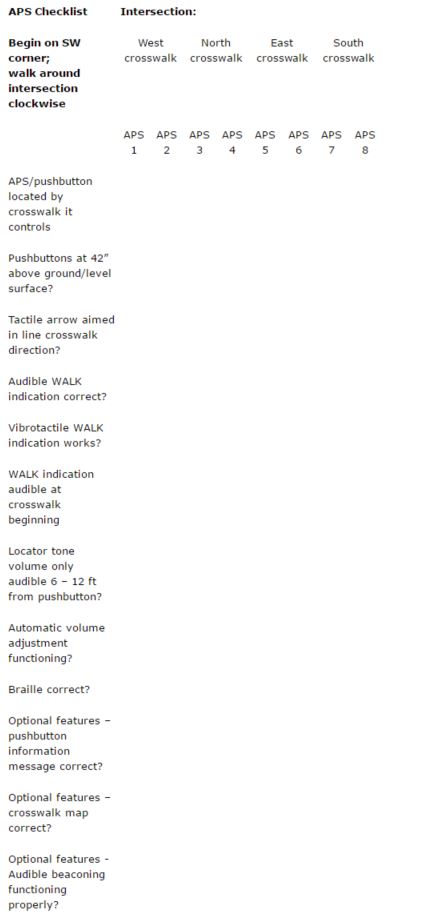
Appendix: Checklist for APR Installations
(adapted from “Accessible Pedestrian Signals: A Guide to Best Practice”, NCHRP Web-only document 117A).
Once installation is complete, the installer should perform the following steps, for each APS at the intersection:
- Check the location of the APS; Is it close to the crosswalk it controls?
- Check the height of the pushbutton
- Check the tactile arrow to be sure it is in line with crosswalk
- Confirm proper functioning of the audible WALK indication
- Confirm proper functioning of the vibrotactile WALK indication
- Evaluate and adjust the WALK indication volume
- Evaluate and adjust the locator tone volume
- Evaluate and set the sensitivity level of the automatic volume adjustment
- Check Braille, if provided
- Check optional features
- Check audible beaconing
Check the location of the APS; is it close to the crosswalk it controls?
Each APS should be close to the crosswalk it controls, preferably in line with the crosswalk line farthest from the intersection. APS for other crosswalk should be farther away, and less audible.
Check Height and Location of the Pushbutton
Confirm that pushbutton height and location conform to specifications and can be reached by a person in a wheelchair, from a hard surfaced level landing.
Check Tactile Arrow
Check that the tactile arrow is aligned in the direction of travel on the crosswalk.
Confirm that the arrow points to the street that is controlled by that pushbutton.
Confirm Proper Functioning of the Audible Walk Indication
Press the button and wait for the Walk indication. Confirm that it sounds at the proper time for the street.
The Walk indication (tone or speech message) should sound for the duration of the walk interval, unless there is a special setting due to a rest in “Walk” situation.
If the Walk indication is a speech message, confirm that it refers to the correct street and is appropriately worded and understandable.
Confirm that the vibrotactile indications work
The tactile arrow or vibrating surface should vibrate rapidly only during the walk interval for the street.
Evaluate and adjust the volume of the Walk indication
Stand at the curb or end of the curb ramp at the crosswalk and listen for the Walk indication. It should be audible from the crossing location, but it should not be audible across the street.
Confirm that the Walk indication for each crosswalk sounds closer than the Walk indication for the perpendicular crosswalk.
Listen through several cycles at times when traffic is noisy and at times when traffic is quiet and adjust the Walk indication volume as necessary.
Evaluate and adjust locator tone volume
Approach the intersection from both directions along the sidewalk and note when the pushbutton locator tone is audible. If there are two pushbutton locator tones at the corner, each should be audible. The pushbutton locator tone should be audible 6 to 12 ft from the pushbutton or at the building line, whichever is closer to the pushbutton.
Approach the corner from the crosswalk and note when the pushbutton locator tone is audible. The pushbutton locator tone should be audible at 6 to 12 ft (or approximately one lane) from the pushbutton.
Listen through several cycles at times when traffic is noisy and at times when traffic is quiet and adjust the locator tone volume as necessary.
Set the Automatic Volume Adjustment
Evaluate and set the sensitivity level of the automatic volume adjustment. If volumes are adequate in quiet conditions, but do not increase enough or quickly enough when ambient noise increases, the microphone sensitivity, or automatic gain control, may need to be increased.
Increase the microphone sensitivity in 10% to 20% steps until the response is as desired. It might be necessary to readjust the volume of the locator tone and Walk indications after the microphone or “dB over ambient” setting is adjusted.
Check Braille
Confirm that braille dots are raised to the touch. If possible, have a person who reads Braille confirm that the name on APS is the name of the street that the arrow points toward.
Check Optional Features, if available
Pushbutton information message - Press the pushbutton for an extended button press to see if the pushbutton information message plays and that it accurately identifies the crossing controlled by the pushbutton and that other information, if provided, is accurate.
Crosswalk map - Confirm that a tactile map accurately represents the crossing features.
Audible beaconing – If installed, press the pushbutton for an extended button press and confirm that the locator tone sound is boosted on that crosswalk during the following pedestrian phase (FDW), and walk across the street during the pedestrian phase and evaluate placement and aiming of devices for providing sound in the crosswalk area.
Recheck Device Functioning at a Later Time
Follow up during the first few weeks after installation, checking device and volume at a different time of day to ensure proper functioning.
Designate a person and phone number to call and report any malfunctioning device. Share that information with agencies serving individuals who are blind and with community organizations of individuals who are blind.
User Comments/Questions
Add Comment/Question