2016 California Standards for Accessible Design Pocket Guide - Eff. Jan. 1, 2017
11B-404.2 Manual doors, doorways, and manual gates.
Manual doors and doorways and manual gates intended for user passage shall comply with Section 11B-404.2.
11B-404.2.1 Revolving doors, gates, and turnstiles.
Revolving doors, revolving gates, and turnstiles shall not be part of an accessible route.
11B-404.2.2 Double-leaf doors and gates.
At least one of the active leaves of doorways with two leaves shall comply with Sections 11B-404.2.3 and 11B-404.2.4.
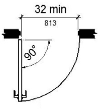
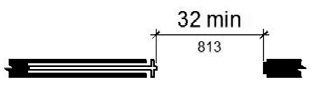
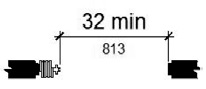
11B-404.2.3 Clear width.
Door openings shall provide a clear width of 32 inches (813 mm) minimum. Clear openings of doorways with swinging doors shall be measured between the face of the door and the stop, with the door open 90 degrees. Openings more than 24 inches (610 mm) deep shall provide a clear opening of 36 inches (914 mm) minimum. There shall be no projections into the required clear opening width lower than 34 inches (864 mm) above the finish floor or ground. Projections into the clear opening width between 34 inches (864 mm) and 80 inches (2032 mm) above the finish floor or ground shall not exceed 4 inches (102 mm).
Exceptions:
1. In alterations, a projection of 5/8 inch (15.9 mm) maximum into the required clear width shall be permitted for the latch side stop.
2. Door closers and door stops shall be permitted to be 78 inches (1981 mm) minimum above the finish floor or ground.
(a)
hinged door
(b)
sliding door
(c)
folding door
FIGURE 11B-404.2.3
CLEAR WIDTH OF DOORWAYS
11B-404.2.4 Maneuvering clearances.
Minimum maneuvering clearances at doors and gates shall comply with Section 11B-404.2.4. Maneuvering clearances shall extend the full width of the doorway and the required latch side or hinge side clearance.
Exception: Reserved.
[2010 ADAS] EXCEPTION: Entry doors to hospital patient rooms shall not be required to provide the clearance beyond the latch side of the door.
ETA Editor's Note
CBC does not include the 2010 ADAS Exception at 404.2.4. Therefore, CBC requirements related to entry doors at patient rooms are more stringent.
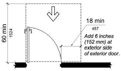
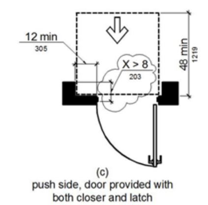
11B-404.2.4.1 Swinging doors and gates.
Swinging doors and gates shall have maneuvering clearances complying with Table 11B-404.2.4.1.
TABLE 11B-404.2.4.1
MANEUVERING CLEARANCES AT MANUAL SWINGING DOORS AND GATES
|
Type of Use |
Minimum Maneuvering Clearance |
||
|---|---|---|---|
|
Approach direction |
Door or gate side |
Perpendicular to doorway |
Parallel to doorway (beyond latch side unless noted) |
|
From front |
Pull |
60 inches (1524 mm) |
18 inches (457 mm)5 |
|
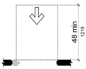
From front |
Push |
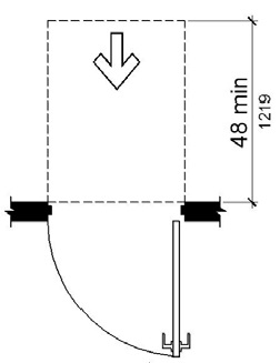
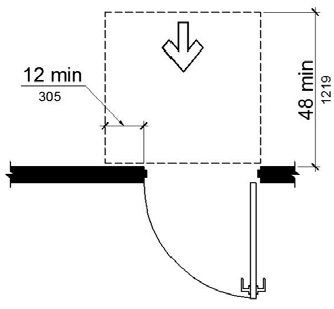
48 inches (1219 mm) |
0 inches (0 mm)1 |
|
From hinge side |
Pull |
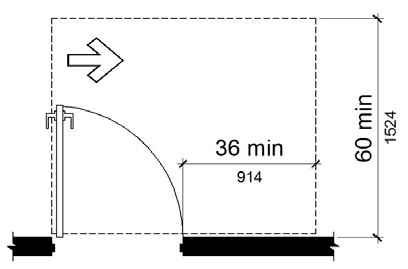
60 inches (1524 mm) |
36 inches (914 mm) |
|
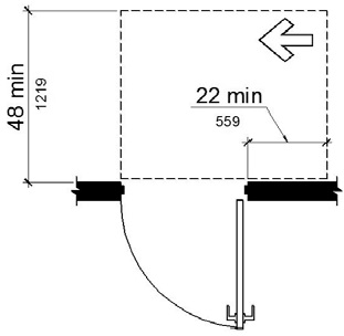
From hinge side |
Push |
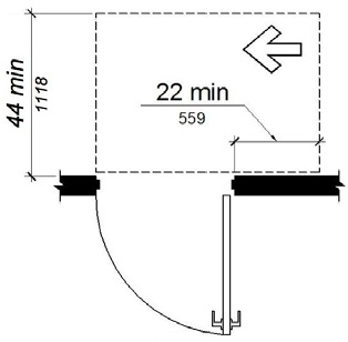
44 inches (1118 mm)2 [2010 ADAS] 42 inches, add 6 inches if closer and latch provided |
22 inches (559 mm)3 |
|
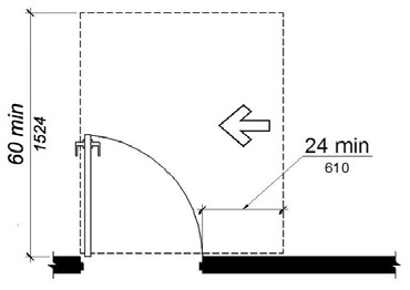
From latch side |
Pull |
60 inches (1524 mm) [2010 ADAS] 48 inches, add 6" if closer provided |
24 inches (610 mm) |
|
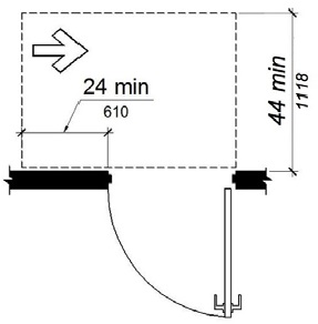
From latch side |
Push |
44 inches (1118 mm)4 [2010 ADAS] 42 inches, add 6" if closer provided |
24 inches (610 mm) |
|
1. Add 12 inches (305 mm) if closer and latch are provided. 2. Add 4 inches (102 mm) if closer and latch are provided. 3. Beyond hinge side. 4. Add 4 inches (102 mm) if closer is provided. 5. Add 6 inches (152 mm) at exterior side of exterior doors. |
|||
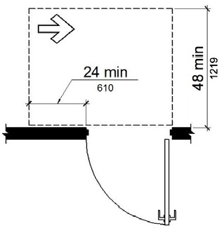
(a)
front approach, pull side
(b)
front approach, push side
(c)
front approach, push side, door provided with both closer and latch
(d)
hinge approach, pull side

(e)
reserved
(f)
hinge approach, push side
(g)
hinge approach, push side, door provided with both closer and latch
(h)
latch approach, pull side
(i)
reserved
(j)
latch approach, push side
(k)
latch approach, push side, door provided with closer
FIGURE 11B-404.2.4.1 ‡‡
MANEUVERING CLEARANCES AT MANUAL SWINGING DOORS AND GATES
11B-404.2.4.2 Doorways without doors or gates, sliding doors, and folding doors.
Doorways less than 36 inches (914 mm) wide without doors or gates, sliding doors, or folding doors shall have maneuvering clearances complying with Table 11B-404.2.4.2.
TABLE 11B-404.2.4.2
MANEUVERING CLEARANCES AT DOORWAYS WITHOUT DOORS OR GATES, MANUAL SLIDING DOORS, AND MANUAL FOLDING DOORS
|
Minimum Maneuvering Clearance |
||
|---|---|---|
|
Approach direction |
Perpendicular to doorway |
Parallel to doorway (beyond stop/latch side unless noted) |
|
From Front |
48 inches (1219 mm) |
0 inches (0 mm) |
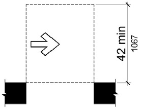
|
From side1 |
42 inches (1067 mm) |
0 inches (0 mm) |
|
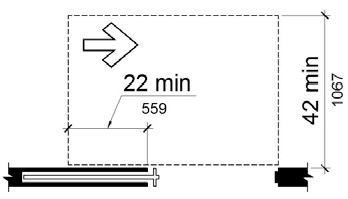
From pocket/hinge side |
42 inches (1067 mm) |
22 inches (559 mm)2 |
|
From stop/latch side |
42 inches (1067 mm) |
24 inches (610 mm) |
|
1. Doorway with no door only. |
||
(a)
front approach
(b)
side approach
(c)
pocket or hinge approach
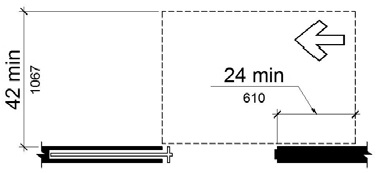
(d)
stop or latch approach
FIGURE 11B-404.2.4.2
MANEUVERING CLEARANCES AT DOORWAYS WITHOUT DOORS, SLIDING DOORS, GATES, AND FOLDING DOORS
11B-404.2.4.3 Recessed doors and gates.
Maneuvering clearances for forward approach shall be provided when any obstruction within 18 inches (457 mm) of the latch side at an interior doorway, or within 24 inches (610 mm) of the latch side of an exterior doorway, projects more than 8 inches (203 mm) beyond the face of the door, measured perpendicular to the face of the door or gate.
[2010 ADAS] 404.2.4.3 Recessed Doors and Gates. Maneuvering clearances for forward approach shall be provided when any obstruction within 18 inches (455 mm) of the latch side of a doorway projects more than 8 inches (205 mm) beyond the face of the door, measured perpendicular to the face of the door or gate.
[2010 ADAS] Advisory 404.2.4.3 Recessed Doors and Gates. A door can be recessed due to wall thickness or because of the placement of casework and other fixed elements adjacent to the doorway. This provision must be applied wherever doors are recessed.
ETA Editor's Note
CBC latch side clearance at exterior doors is more stringent than 2010 ADAS.
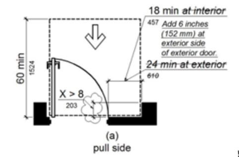
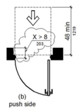
Figure 11B-404.2.4.3 Maneuvering Clearances at Recessed Doors and Gates
11B-404.2.4.4 Floor or ground surface.
Floor or ground surface within required maneuvering clearances shall comply with Section 11B-302. Changes in level are not permitted.
Exceptions:
1. Slopes not steeper than 1:48 shall be permitted.
2. Changes in level at thresholds complying with Section 11B-404.2.5 shall be permitted.
11B-404.2.5 Thresholds.
Thresholds, if provided at doorways, shall be ½ inch (12.7 mm) high maximum. Raised thresholds and changes in level at doorways shall comply with Sections 11B-302 and 11B-303.
Exception: Reserved.
[2010 ADAS] EXCEPTION: Existing or altered thresholds ¾ inch (19 mm) high maximum that have a beveled edge on each side with a slope not steeper than 1:2 shall not be required to comply with 404.2.5.
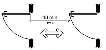
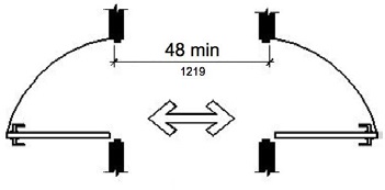
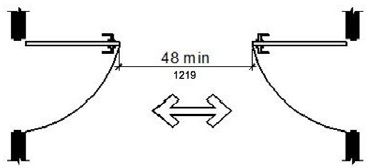
11B-404.2.6 Doors in series and gates in series.
The distance between two hinged or pivoted doors in series and gates in series shall be 48 inches (1219 mm) minimum plus the width of doors or gates swinging into the space.
(a)
(b)
(c)
FIGURE 11B-404.2.6
DOORS IN SERIES AND GATES IN SERIES
11B-404.2.7 Door and gate hardware.
Handles, pulls, latches, locks, and other operable parts on doors and gates shall comply with Section 11B-309.4. Operable parts of such hardware shall be 34 inches (864 mm) minimum and 44 inches (1118 mm) maximum above the finish floor or ground. Where sliding doors are in the fully open position, operating hardware shall be exposed and usable from both sides.
Exceptions:
1. Existing locks shall be permitted in any location at existing glazed doors without stiles, existing overhead rolling doors or grilles, and similar existing doors or grilles that are designed with locks that are activated only at the top or bottom rail.
2. Access gates in barrier walls and fences protecting pools, spas, and hot tubs shall be permitted to have operable parts of the release of latch on self-latching devices at 54 inches (1372 mm) maximum above the finish floor or ground provided the self-latching devices are not also self-locking devices and operated by means of a key, electronic opener, or integral combination lock.
[2010 ADAS] 404.2.7 Door and Gate Hardware. Handles, pulls, latches, locks, and other operable parts on doors and gates shall comply with 309.4. Operable parts of such hardware shall be 34 inches (865 mm) minimum and 48 inches (1220 mm) maximum above the finish floor or ground. Where sliding doors are in the fully open position, operating hardware shall be exposed and usable from both sides.
EXCEPTIONS: 1. Existing locks shall be permitted in any location at existing glazed doors without stiles, existing overhead rolling doors or grilles, and similar existing doors or grilles that are designed with locks that are activated only at the top or bottom rail.
2. Access gates in barrier walls and fences protecting pools, spas, and hot tubs shall be permitted to have operable parts of the release of latch on self-latching devices at 54 inches (1370 mm) maximum above the finish floor or ground provided the self-latching devices are not also self-locking devices and operated by means of a key, electronic opener, or integral combination lock.
[2010 ADAS] Advisory 404.2.7 Door and Gate Hardware. Door hardware that can be operated with a closed fist or a loose grip accommodates the greatest range of users. Hardware that requires simultaneous hand and finger movements require greater dexterity and coordination and is not recommended.

11B-404.2.8 Closing speed.
Door and gate closing speed shall comply with Section 11B-404.2.8.
11B-404.2.8.1 Door closers and gate closers.
Door closers and gate closers shall be adjusted so that from an open position of 90 degrees, the time required to move the door to a position of 12 degrees from the latch is 5 seconds minimum.
11B-404.2.8.2 Spring hinges.
Door and gate spring hinges shall be adjusted so that from the open position of 70 degrees, the door or gate shall move to the closed position in 1.5 seconds minimum.
11B-404.2.9 Door and gate opening force.
The force for pushing or pulling open a door or gate shall be as follows:
[2010 ADAS] 404.2.9 Door and Gate Opening Force. Fire doors shall have a minimum opening force allowable by the appropriate Administrative Authority. The force for pushing or pulling open a door or gate other than fire doors shall be as follows:
1. Interior hinged doors and gates: 5 pounds (22.2 N) maximum.
2. Sliding or folding doors: 5 pounds (22.2 N) maximum.
3. Required fire doors: the minimum opening force allowable by the appropriate administrative authority, not to exceed 15 pounds (66.7 N).
4. Exterior hinged doors: 5 pounds (22.2 N) maximum.
These forces do not apply to the force required to retract latch bolts or disengage other devices that hold the door or gate in a closed position.
[2010 ADAS] Advisory 404.2.9 Door and Gate Opening Force. The maximum force pertains to the continuous application of force necessary to fully open a door, not the initial force needed to overcome the inertia of the door. It does not apply to the force required to retract bolts or to disengage other devices used to keep the door in a closed position.
Exception: When, at a single location, one of every eight exterior door leafs, or fraction of eight, is a powered door, other exterior doors at the same location, serving the same interior space, may have a maximum opening force of 8.5 pounds (37.8 N). The powered leaf(s) shall be located closest to the accessible route.
a. Powered doors shall comply with Section 11B-404.3. Powered doors shall be fully automatic doors complying with Builders Hardware Manufacturers’ Association (BHMA) A156.10 or low energy operated doors complying with BHMA A156.19.
b. Powered doors serving a building or facility with an occupancy of 150 or more shall be provided with a back-up battery or back-up generator. The back-up power source shall be able to cycle the door a minimum of 100 cycles.
c. Powered doors shall be controlled on both the interior and exterior sides of the doors by sensing devices, push plates, vertical actuation bars or other similar operating devices complying with Sections 11B-304 _|Turning Space|_, 11B-305 _|Clear Floor or Ground Space|_ and 11B-308 _|Reach Ranges|_.
At each location where push plates are provided there shall be two push plates; the centerline of one push plate shall be 7 inches (178 mm) minimum and 8 inches (203 mm) maximum above the floor or ground surface and the centerline of the second push plate shall be 30 inches (762 mm) minimum and 44 inches (1118 mm) maximum above the floor or ground surface. Each push plate shall be a minimum of 4 inches (102 mm) diameter or a minimum of 4 inches by 4 inches (102 mm by 102 mm) square and shall display the International Symbol of Accessibility complying with Section 11B-703.7.
At each location where vertical actuation bars are provided the operable portion shall be located so the bottom is 5 inches (127 mm) maximum above the floor or ground surface and the top is 35 inches (889 mm) minimum above the floor or ground surface. The operable portion of each vertical actuation bar shall be a minimum of 2 inches (51 mm) wide and shall display the International Symbol of Accessibility complying with Section 11B-703.7.
Where push plates, vertical actuation bars or other similar operating devices are provided, they shall be placed in a conspicuous location. A level and clear floor or ground space for forward or parallel approach complying with Section 11B-305 shall be provided, centered on the operating device. Doors shall not swing into the required clear floor or ground space.
d. Signs identifying the accessible entrance required by Section 11B-216.6 shall be placed on, or immediately adjacent to, each powered door. Signs shall be provided in compliance with BHMA A156.10 or BHMA 156.19, as applicable.
e. In addition to the requirements of Item d, where a powered door is provided in buildings or facilities containing assembly occupancies of 300 or more, a sign displaying the International Symbol of Accessibility measuring 6 inches by 6 inches (152 mm by 152 mm), complying with Section 11B-703.7, shall be provided above the door on both the interior and exterior sides of each powered door.
ETA Editor's Note
The CBC limitation for opening force at non-rated exterior doors is more stringent than 2010 ADAS, and can be difficult to meet without a powered device at exterior doors exposed to wind, or leading from spaces that operate at negative pressure with respect to the exterior environment. That is the principle reason for the preceding Exception to 11B-404.2.9 that does not appear in 2010 ADAS.
11B-404.2.10 Door and gate surfaces.
Swinging door and gate surfaces within 10 inches (254 mm) of the finish floor or ground measured vertically shall have a smooth surface on the push side extending the full width of the door or gate. Parts creating horizontal or vertical joints in these surfaces shall be within 1/16 inch (1.6 mm) of the same plane as the other and be free of sharp or abrasive edges. Cavities created by added kick plates shall be capped.
Exceptions:
1. Sliding doors shall not be required to comply with Section 11B-404.2.10.
2. Tempered glass doors without stiles and having a bottom rail or shoe with the top leading edge tapered at 60 degrees minimum from the horizontal shall not be required to meet the 10 inch (254 mm) bottom smooth surface height requirement.
3. Doors and gates that do not extend to within 10 inches (254 mm) of the finish floor or ground shall not be required to comply with Section 11B-404.2.10.
4. Reserved.
[2010 ADAS] 4. Existing doors and gates without smooth surfaces within 10 inches (255 mm) of the finish floor or ground shall not be required to provide smooth surfaces complying with 404.2.10 provided that if added kick plates are installed, cavities created by such kick plates are capped.
ETA Editor's Note
Lacking Exception 4 at 11B-404.2.10, CBC is more stringent at existing doors than 2010 ADAS.
11B-404.2.11 Vision lights.
Doors, gates, and side lights adjacent to doors or gates, containing one or more glazing panels that permit viewing through the panels shall have the bottom of at least one glazed panel located 43 inches (1092 mm) maximum above the finish floor.
Exception: Glazing panels with the lowest part more than 66 inches (1676 mm) from the finish floor or ground shall not be required to comply with Section 11B-404.2.11.
ETA Editor's Note
The vision light requirement of CBC 11B-404.2.11 is derived from 2010 ADAS 404.2.11. Under ADA, an existing door with a noncompliant vision light is a Safe Harbored element for path of travel and barrier removal purposes, but will have to comply when the door is replaced, and may not be relocated elsewhere on an accessible route. Under CBC, an existing primary entrance door with a noncompliant vision light is not Safe Harbored, unless the Exception at 11B-404.2.11 applies, and must be mitigated under path of travel obligations.
User Comments/Questions
Add Comment/Question