404.2 Manual Doors, Doorways, and Manual Gates.
Manual doors and doorways and manual gates intended for user passage shall comply with 404.2.
404.2.1 Revolving Doors, Gates, and Turnstiles.
Revolving doors, revolving gates, and turnstiles shall not be part of an accessible route.
404.2.2 Double-Leaf Doors and Gates.
At least one of the active leaves of doorways with two leaves shall comply with 404.2.3 and 404.2.4.
404.2.3 Clear Width.
Door openings shall provide a clear width of 32 inches (815 mm) minimum. Clear openings of doorways with swinging doors shall be measured between the face of the door and the stop, with the door open 90 degrees. Openings more than 24 inches (610 mm) deep shall provide a clear opening of 36 inches (915 mm) minimum. There shall be no projections into the required clear opening width lower than 34 inches (865 mm) above the finish floor or ground. Projections into the clear opening width between 34 inches (865 mm) and 80 inches (2030 mm) above the finish floor or ground shall not exceed 4 inches (100 mm).
EXCEPTIONS:
1. In alterations, a projection of 5/8 inch (16 mm) maximum into the required clear width shall be permitted for the latch side stop.
2. Door closers and door stops shall be permitted to be 78 inches (1980 mm) minimum above the finish floor or ground.
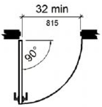
(a)
hinged door
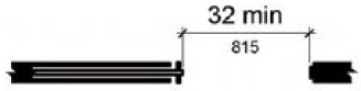
(b)
sliding door
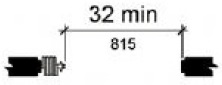
(c)
folding door
Figure 404.2.3 Clear Width of Doorways
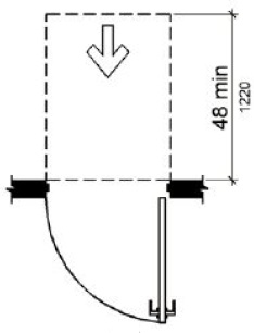
404.2.4 Maneuvering Clearances.
Minimum maneuvering clearances at doors and gates shall comply with 404.2.4. Maneuvering clearances shall extend the full width of the doorway and the required latch side or hinge side clearance.
EXCEPTION: Entry doors to hospital patient rooms shall not be required to provide the clearance beyond the latch side of the door.
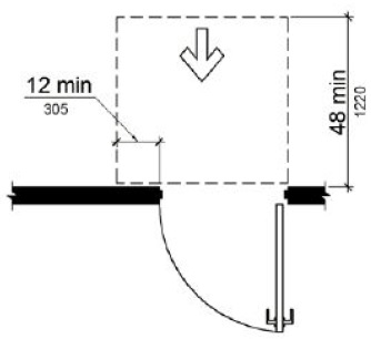
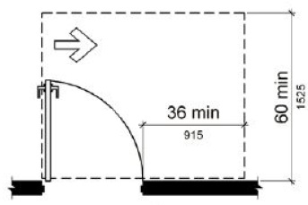
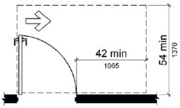
404.2.4.1 Swinging Doors and Gates.
Swinging doors and gates shall have maneuvering clearances complying with Table 404.2.4.1.
| Type of Use | Minimum Maneuvering Clearance | ||
|---|---|---|---|
| Approach Direction | Door or Gate Side | Perpendicular to Doorway | Parallel to Doorway (beyond latch side unless noted) |
| From front | Pull | 60 inches (1525 mm) | 18 inches (455 mm) |
| From front | Push | 48 inches (1220 mm) | 0 inches (0 mm)1 |
| From hinge side | Pull | 60 inches (1525 mm) | 36 inches (915 mm) |
| From hinge side | Pull | 54 inches (1370 mm) | 42 inches (1065 mm) |
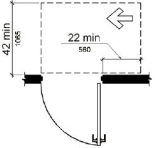
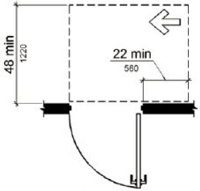
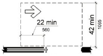
| From hinge side | Push | 42 inches (1065 mm)2 | 22 inches (560 mm)3 |
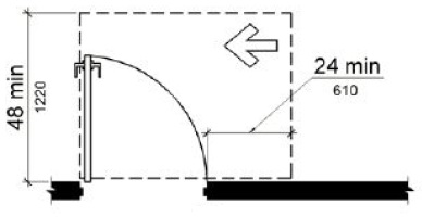
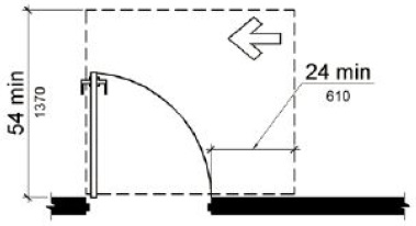
| From latch side | Pull | 48 inches (1220 mm)4 | 24 inches (610 mm) |
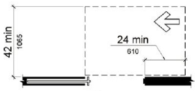
| From latch side | Push | 42 inches (1065 mm)4 | 24 inches (610 mm) |
1. Add 12 inches (305 mm) if closer and latch are provided.
2. Add 6 inches (150 mm) if closer and latch are provided.
3. Beyond hinge side.
4. Add 6 inches (150 mm) if closer is provided.
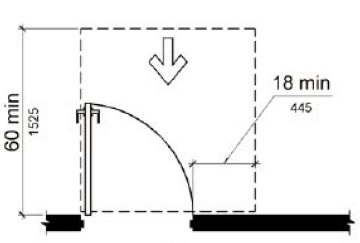
(a)
front approach, pull side
(b)
front approach, push side
(c)
front approach, push side, door provided with both closer and latch
(d)
hinge approach, pull side
(e)
hinge approach, pull side
(f)
hinge approach, push side
(g)
hinge approach, push side, door provided with both closer and latch
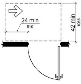
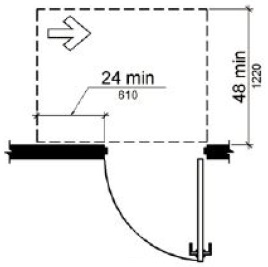
(h)
latch approach, pull side
(i)
latch approach, pull side, door provided with closer
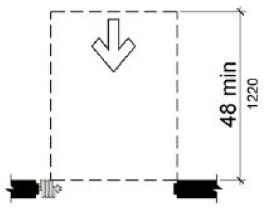
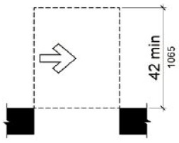
(j)
latch approach, push side
(k)
latch approach, push side, door provided with closer
Figure 404.2.4.1 Maneuvering Clearances at Manual Swinging Doors and Gates
404.2.4.2 Doorways without Doors or Gates, Sliding Doors, and Folding Doors.
Doorways less than 36 inches (915 mm) wide without doors or gates, sliding doors, or folding doors shall have maneuvering clearances complying with Table 404.2.4.2.
Table 404.2.4.2 Maneuvering Clearances at Doorways without Doors or Gates, Manual Sliding Doors, and Manual Folding Doors
| Minimum Maneuvering Clearance | ||
| Approach Direction | Perpendicular to Doorway | Parallel to Doorway (beyond stop/latch side unless noted) |
| From Front | 48 inches (1220 mm) | 0 inches (0 mm) |
| From side1 | 42 inches (1065 mm) | 0 inches (0 mm) |
| From pocket/hinge side | 42 inches (1065 mm) | 22 inches (560 mm)2 |
| From stop/latch side | 42 inches (1065 mm) | 24 inches (610 mm) |
1. Doorway with no door only.
2. Beyond pocket/hinge side.
(a)
front approach
(b)
side approach
(c)
pocket or hinge approach
(d)
stop or latch approach
Figure 404.2.4.2 Maneuvering Clearances at Doorways Without Doors, Sliding Doors, Gates, and Folding Doors
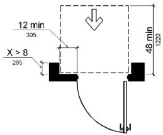
404.2.4.3 Recessed Doors and Gates.
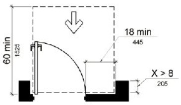
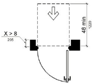
Maneuvering clearances for forward approach shall be provided when any obstruction within 18 inches (455 mm) of the latch side of a doorway projects more than 8 inches (205 mm) beyond the face of the door, measured perpendicular to the face of the door or gate.
Advisory 404.2.4.3 Recessed Doors and Gates. A door can be recessed due to wall thickness or because of the placement of casework and other fixed elements adjacent to the doorway. This provision must be applied wherever doors are recessed.
(a)
pull side
(b)
push side
(c)
push side, door provided with both closer and latch
Figure 404.2.4.3 Maneuvering Clearances at Recessed Doors and Gates
404.2.4.4 Floor or Ground Surface.
Floor or ground surface within required maneuvering clearances shall comply with 302. Changes in level are not permitted.
EXCEPTIONS:
1. Slopes not steeper than 1:48 shall be permitted.
2. Changes in level at thresholds complying with 404.2.5 shall be permitted.
404.2.5 Thresholds.
Thresholds, if provided at doorways, shall be 1/2 inch (13 mm) high maximum. Raised thresholds and changes in level at doorways shall comply with 302 and 303.
EXCEPTION: Existing or altered thresholds 3/4 inch (19 mm) high maximum that have a beveled edge on each side with a slope not steeper than 1:2 shall not be required to comply with 404.2.5.
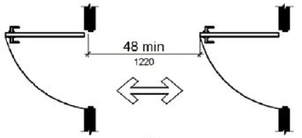
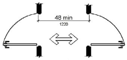
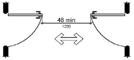
404.2.6 Doors in Series and Gates in Series.
The distance between two hinged or pivoted doors in series and gates in series shall be 48 inches (1220 mm) minimum plus the width of doors or gates swinging into the space.
(a)
(b)
(c)
Figure 404.2.6 Doors in Series and Gates in Series
404.2.7 Door and Gate Hardware.
Handles, pulls, latches, locks, and other operable parts on doors and gates shall comply with 309.4. Operable parts of such hardware shall be 34 inches (865 mm) minimum and 48 inches (1220 mm) maximum above the finish floor or ground. Where sliding doors are in the fully open position, operating hardware shall be exposed and usable from both sides.
EXCEPTIONS:
1. Existing locks shall be permitted in any location at existing glazed doors without stiles, existing overhead rolling doors or grilles, and similar existing doors or grilles that are designed with locks that are activated only at the top or bottom rail.
2. Access gates in barrier walls and fences protecting pools, spas, and hot tubs shall be permitted to have operable parts of the release of latch on self-latching devices at 54 inches (1370 mm) maximum above the finish floor or ground provided the self-latching devices are not also self-locking devices and operated by means of a key, electronic opener, or integral combination lock.
Advisory 404.2.7 Door and Gate Hardware. Door hardware that can be operated with a closed fist or a loose grip accommodates the greatest range of users. Hardware that requires simultaneous hand and finger movements require greater dexterity and coordination, and is not recommended.
404.2.8 Closing Speed.
Door and gate closing speed shall comply with 404.2.8.
404.2.8.1 Door Closers and Gate Closers.
Door closers and gate closers shall be adjusted so that from an open position of 90 degrees, the time required to move the door to a position of 12 degrees from the latch is 5 seconds minimum.
404.2.8.2 Spring Hinges.
Door and gate spring hinges shall be adjusted so that from the open position of 70 degrees, the door or gate shall move to the closed position in 1.5 seconds minimum.
404.2.9 Door and Gate Opening Force.
Fire doors shall have a minimum opening force allowable by the appropriate administrative authority. The force for pushing or pulling open a door or gate other than fire doors shall be as follows:
1. Interior hinged doors and gates: 5 pounds (22.2 N) maximum.
2. Sliding or folding doors: 5 pounds (22.2 N) maximum.
These forces do not apply to the force required to retract latch bolts or disengage other devices that hold the door or gate in a closed position.
Advisory 404.2.9 Door and Gate Opening Force. The maximum force pertains to the continuous application of force necessary to fully open a door, not the initial force needed to overcome the inertia of the door. It does not apply to the force required to retract bolts or to disengage other devices used to keep the door in a closed position.
404.2.10 Door and Gate Surfaces.
Swinging door and gate surfaces within 10 inches (255 mm) of the finish floor or ground measured vertically shall have a smooth surface on the push side extending the full width of the door or gate. Parts creating horizontal or vertical joints in these surfaces shall be within 1/16 inch (1.6 mm) of the same plane as the other. Cavities created by added kick plates shall be capped.
ETA Editor’s Note:
An existing door with a noncompliant kick plate is a safe harbored element for path of travel and barrier removal purposes but will have to comply when the door is replaced.
EXCEPTIONS:
1. Sliding doors shall not be required to comply with 404.2.10.
2. Tempered glass doors without stiles and having a bottom rail or shoe with the top leading edge tapered at 60 degrees minimum from the horizontal shall not be required to meet the 10 inch (255 mm) bottom smooth surface height requirement.
3. Doors and gates that do not extend to within 10 inches (255 mm) of the finish floor or ground shall not be required to comply with 404.2.10.
4. Existing doors and gates without smooth surfaces within 10 inches (255 mm) of the finish floor or ground shall not be required to provide smooth surfaces complying with 404.2.10 provided that if added kick plates are installed, cavities created by such kick plates are capped.
404.2.11 Vision Lights.
Doors, gates, and side lights adjacent to doors or gates, containing one or more glazing panels that permit viewing through the panels shall have the bottom of at least one glazed panel located 43 inches (1090 mm) maximum above the finish floor.
ETA Editor’s Note:
An existing door with a noncompliant vision light is a safe harbored element for path of travel and barrier removal purposes but will have to comply when the door is replaced.
EXCEPTION: Vision lights with the lowest part more than 66 inches (1675 mm) from the finish floor or ground shall not be required to comply with 404.2.11.
User Comments/Questions
Add Comment/Question