2.3 Infrared (IR) Systems
An IR system transmits audio signals via invisible infrared light waves. The frequency of infrared light falls somewhere between 700 nm and 1000+ nm; visible light waves fall between 400 and 700 nm. The specific bandwidth of the IR carrier varies among manufacturers; it may be as narrow as 50 nm wide, or considerably broader and perhaps be visible as a faint reddish glow (Laszlo l998). The audio signal, from any source, is used to frequency modulate an RF sub-carrier which in turn is impressed upon, and essentially amplitude modulates, the IR carrier. An FM/AM double modulation of the IR light wave is the result. Up to now, 95 kHz has been the RF sub-carrier most often used by manufacturers but this may now be changing (more on this below).
To achieve the best possible audio reception, the modulation characteristics of the RF carrier is typically +/- 50 kHz. IR systems are also frequently used with normal hearing people during events requiring simultaneous translation into several languages. In these instances, a number of other sub-carriers may be used, each narrower than the bandwidth used for people with hearing loss.
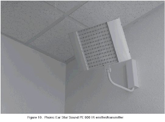
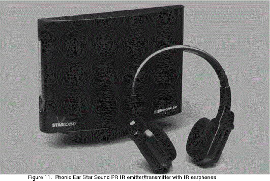
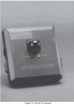
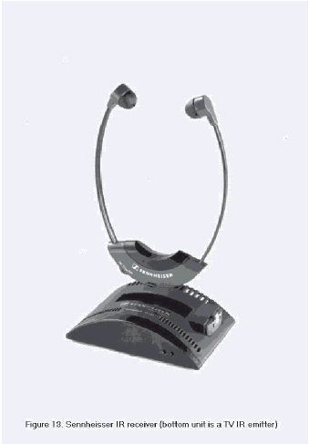
All IR systems are composed of three basic components: the transmitter (also called the modulator), the emitter and the IR receiver. The modulator processes the audio signal so that it can be transmitted via infrared light. This audio processing may include some kind of output limiting, companding (designed to control widely varying amplitude levels), high frequency pre-emphasis and/or high pass filtering. These appear to be similar pre-processing strategies that are used with large-area FM ALS. Examples of IR transmitter/emitters and receivers can be seen in figures 10, 11, 12, and 13.


The signal from the modulator (transmitter) is delivered to emitters that actually produce the IR light waves (these two components may be contained within the same physical unit). The emitter is composed of a number of light emitting diodes (the "light bulbs" of an IR system). Until quite recently, the more diodes contained within an emitter, the more powerful the system. However, with the development of more powerful diodes, this is no longer necessarily true. Although these light waves are invisible to the human eye, they are light waves with certain definable characteristics. This fact may help us understand some of the issues related to IR systems, such as the effects of sunlight and incandescent light (these contain a great deal of infrared energy) and the impact that the color and texture of the wall surfaces have upon IR reflections. Ensuring the appropriate number and placement of emitters is the major challenge facing an installer of IR systems.
The third basic component is the IR receiver. The transparent lens found on every IR receiver contains the photo detector diode that detects the IR light wave. An optical filter on the lens reduces at least some of the light interference from extraneous sources. The IR receiver then demodulates the RF sub-carrier and the audio signal is retrieved and amplified. If the audio signal has been pre-processed in some fashion, such as providing high frequency pre-emphasis or sent through a companding circuit, then it is at this stage that individualized compensation can occur. One reason that the IR systems of different companies are not always compatible, even though they may use the same sub-carrier frequency, is because they may differ in the nature of their pre-processing strategies and compensatory receiver characteristics. While a signal may be received, and even understood, this incompatibility would reduce its clarity.
2.3.1 Standards
There are no standards that we are aware of that specifically cover the unique aspects of IR systems. The New York Standards, quoted in respect to IL and FM installations, do not provide this information; rather these standards basically focus on the electroacoustic output from the IR receivers. When the NYS standards were drafted in l988‒89, the manufacturers could not reach a consensus regarding minimum energy level of the IR light at a set distance from the emitters. Instead a general recommendation was made that the minimum light level must be sufficient so that receivers could produce the required output signal specifications (Johnstone l999).
2.3.2 IR Receivers
A number of different types of IR receivers are used. In one of the most common, the sound tubes are placed in each ear and the unit itself dangles under the chin. Sometimes this is called a stethoset or stethophone receiver. The lens of the receiving diode usually faces forward, toward the presumed location of an emitter. In traversing the tubing leading from the receiver to the eartips, the frequency response of the acoustic signal may display several resonant peaks (Nabalek, Donahue, & Letowski l986). Recently, however, receivers have been developed that locates the transducer at the earphone tips thus precluding the formation of resonant peaks. Some under-chin receivers include an output jack into which a neckloop can be plugged for inductive coupling to a hearing aid. However, these are generally designed for micro-mini plugs and will not accept the mini plug used with neck loops designed for body worn receivers. Some receivers include an environmental microphone to permit the direct audio reception of one's companions while using the IR receiver. Acoustical coupling through personal hearing aids is not feasible with this type of receiver.
Some IR receivers are built into headphones. In these instances, the receiving diode can be placed within an oblong lens on the top of the headband, for presumably 360 degree reception, or appear as a rounded protuberance on the surface of each earphone. The "best" position for receiving IR signals depend upon the relative positions of the emitter and the receiving diodes. Some IR headphones allow for possible acoustical coupling, in that they can be placed right over hearing aids (not the BTE type, however). As pointed out earlier, the incidence of acoustical coupling upon the production of acoustic feedback, or undesirable changes in the frequency response of the hearing aid, has not been determined with this type of acoustical coupling. Many hearing aid users prefer to remove the aids before placing the headphones on and listening through headphone alone.
Body IR receivers look like personal listening systems or FM receivers. They are distinguished from these by the presence of the visible translucent lens on the front surface (presumably facing the light source, i.e. the emitter). This type of receiver would not be too useful when the emitter is directly overhead, in a darkened theater for example. The other coupling choices - inductive, acoustical (headphones worn over personal hearing aids), or headphones or earbuds directly - are the same as that used with FM receivers. Some IR receivers include an environmental microphone and some do not. No IR receiver, as far as we know, provides a low battery light feature.
2.3.3 Issues
* Up to now, 95 kHz has been the sub-carrier most frequently used by manufacturers of IR systems. When stereo reception was desired, a sub-carrier of 250 kHz was simultaneously employed. These frequencies reflected an informal agreement among manufacturers rather than any national or international standards (Lieske l994). Other frequencies are now being used as sub-carriers in ALS (300 kHz, 2.3 mHz and 2.8 mHz).
One reason for switching to a higher sub-carrier frequency is because of the electromagnetic interference at 95 kHz produced by the newly introduced T−12 fluorescent ballasts. Since these are more energy efficient than the older type of ballast (type T−8), their use is likely to increase in the future. In other words, the pre-eminence of the 95 kHz sub-carrier is no longer assured. While it does not appear to be on its way out, it may be employed in fewer locations. Compatibility between venues has been an advantageous feature of IR but, with the introduction of different sub-carriers, this advantage can no longer be taken for granted.
* The frequency of the sub-carrier is not the only uncontrolled factor in IR systems. Unlike RF fields, the strength of the IR field is left up to the manufacturers and installers. To reduce the interference effect of ambient light, a manufacturer may increase the radiated IR light level and decrease the sensitivity of the IR receiver. Other manufacturers may radiate less light energy from their emitters and depend upon the sensitivity and electronics of the receivers to detect an adequate signal. These factors help explain the variation in performance of different IR receivers in a specific venue, even when they all use the same sub-carrier frequency.
* IR receiver diodes generally detect a broad bandwidth of light, extending over 500 nm. Every receiver uses filters built into the detector diode that is designed to accept the transmitter frequency and block the other IR light (Laszlo l998). However, the filter characteristics cannot be too narrow, else slight transmitter "drifts", perhaps due to temperature effects may put the device outside the passband. This effect can be compensated for with more expensive electronics, but then the decision becomes a cost/benefit issue. The specific characteristics of these filters presumably differ among the receivers from different manufacturers and are another reason why, in spite of using the same sub-carrier frequency, some IR receivers are less compatible than others in the same location.
* IR light waves are considered "line of sight" transmission. That is, ordinarily the "eye" of the emitter should be facing the "eye" of the receiver, with no physical obstructions placed between these two devices. Turning one's back to the emitter, or placing an IR receiver in one's pocket, can either eliminate or distort the perceived audio signal. However, line of sight reception is affected by surface material (light surfaces reflect more light energy), the strength of the transmitted signal, and the geometric shape and number of listening levels (e.g. balconies) in the venue. In rooms with light covered surfaces, these reflections may enhance IR coverage by filling in gaps not covered by the primary signal. Conversely, with dark surface, or checkerboard patterns, may reduce or modify IR light reflections. Reportedly, a few recently introduced IR transmitters are capable of being employed in some outdoor venues (but not in direct sunlight).
* The emitters produce an ovoid IR light pattern that diminishes in strength following the inverse-square law. This means that a number of emitters must be used to ensure that all seats in a venue, such as in the corners or in the rear of the room, receive an "adequate" level of the light. Installers frequently "daisy-chain" emitters to guarantee that IR light is being directed at the audience from several directions. There are no standards which specify the radiated level of light required at seat locations. At least one manufacturer (Audex) makes a light meter available for installers. This particular lightmeter is designed only with the company's own products in mind, in that it reads only relative light intensity for determining whether the illumination levels are satisfactory. Installers also can, and usually do, listen through a receiver at various seat locations. This is a highly subjective judgment and offers hard of hearing listeners no assurance of adequate IR field strength at all seat locations in a venue. One of the recurring complaints made by the consumers in the focus group was the variations they experienced in IR field strength and the clarity of the IR signal in different venues and at different locations in the same venue.

User Comments/Questions
Add Comment/Question