Appendix to Part 38—Guidance Material
[56 FR 45756, Sept. 6, 1991, as amended at 63 FR 51702, 51703, Sept. 28, 1998; 79 FR 21407, Apr. 16, 2014]
This appendix contains materials of an advisory nature and provides additional information that should help the reader to understand the minimum requirements of the standards or to design vehicles for greater accessibility. Each entry is applicable to all subparts of this part except where noted. Nothing in this appendix shall in any way obviate any obligation to comply with the requirements of the standards themselves.
I. Slip Resistant Surface—Aisles, Steps, Floor Areas Where People Walk, Floor Areas in Securement Locations, Lift Platforms, Ramps
Slip resistance is based on the frictional force necessary to keep a shoe heel or crutch tip from slipping on a walking surface under conditions likely to be found on the surface. While the dynamic coefficient of friction during walking varies in a complex and non-uniform way, the static coefficient of friction, which can be measured in several ways, provides a close approximation of the slip resistance of a surface. Contrary to popular belief, some slippage is necessary to walking, especially for persons with restricted gaits; a truly “non-slip” surface could not be negotiated.
The Occupational Safety and Health Administration recommends that walking surfaces have a static coefficient of friction of 0.5. A research project sponsored by the Architectural and Transportation Barriers Compliance Board (Access Board) conducted tests with persons with disabilities and concluded that a higher coefficient of friction was needed by such persons. A static coefficient of friction of 0.6 is recommended for steps, floors, and lift platforms and 0.8 for ramps.
It is recognized that the coefficient of friction varies considerably due to the presence of contaminants, water, floor finishes, and other factors not under the control of transit providers and may be difficult to measure. Nevertheless, many common materials suitable for flooring are now labeled with information on the static coefficient of friction. While it may not be possible to compare one product directly with another, or to guarantee a constant measure, transit operators or vehicle designers and manufacturers are encouraged to specify materials with appropriate values. As more products include information on slip resistance, improved uniformity in measurement and specification is likely. The Access Board's advisory guidelines on Slip Resistant Surfaces provides additional information on this subject.
II. Color Contrast—Step Edges, Lift Platform Edges
The material used to provide contrast should contrast by at least 70%. Contrast in percent is determined by:
Contrast=[B−B)/B]×100
Where B=light reflectance value (LRV) of the lighter area
and B=light reflectance value (LRV) of the darker area.
Note that in any application both white and black are never absolute; thus, B never equals 100 and B is always greater than 0.
III. Handrails and Stanchions
In addition to the requirements for handrails and stanchions for rapid, light, and commuter rail vehicles, consideration should be given to the proximity of handrails or stanchions to the area in which wheelchair or mobility aid users may position themselves. When identifying the clear floor space where a wheelchair or mobility aid user can be accommodated, it is suggested that at least one such area be adjacent or in close proximity to a handrail or stanchion. Of course, such a handrail or stanchion cannot encroach upon the required 32 inch width required for the doorway or the route leading to the clear floor space which must be at least 30 by 48 inches in size.
IV. Priority Seating Signs and Other Signage
A. Finish and Contrast. The characters and background of signs should be eggshell, matte, or other non-glare finish. An eggshell finish (11 to 19 degree gloss on 60 degree glossimeter) is recommended. Characters and symbols shall contrast with their background—either light characters on a dark background or dark characters on a light background. Research indicates that signs are more legible for persons with low vision when characters contrast with their background by at least 70 percent. Contrast in percent shall be determined by:
Contrast=[B−B)/B] × 100
Where B = light reflectance value (LRV) of the lighter area
and B = light reflectance value (LRV) of the darker area.
Note that in any application both white and black are never absolute; thus, B never equals 100 and B is always greater than 0.
The greatest readability is usually achieved through the use of light-colored characters or symbols on a dark background.
B. Destination and Route Signs. (The following specifications, which are required for buses (§38.39), are recommended for other types of vehicles, particularly light rail vehicles, were appropriate.)
1. Where destination or route information is displayed on the exterior of a vehicle, each vehicle shall have illuminated signs on the front and boarding side of the vehicle.
2. Characters on signs required by paragraph IV.B.1 of this appendix shall have a width-to-height ratio between 3:5 and 1:1 and a stroke width-to-height ratio between 1:5 and 1:10, with a minimum character height (using an upper case “X”) of 1 inch for signs on the boarding side and a minimum character height of 2 inches for front “headsigns,” with “wide” spacing (generally, the space between letters shall be 1/16 the height of upper case letters), and shall contrast with the background, either dark-on-light or light-on-dark, or as recommended above.
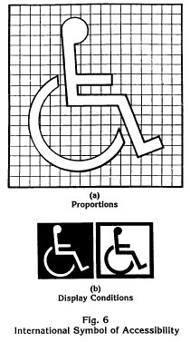
C. Designation of Accessible Vehicles. The International Symbol of Accessibility should be displayed as shown in Figure 6.
V. Public Information Systems
Entities are encouraged to employ any available services, signage, or alternative systems or devices that are capable of providing the same or equivalent information to persons with hearing loss. Two possible types of devices are visual display systems and listening systems. However, it should be noted that while visual display systems accommodate persons who are deaf or are hearing impaired, assistive listening systems aid only those with a partial loss of hearing.
A. Visual Display Systems. Announcements may be provided in a visual format by the use of electronic message boards or video monitors.
Electronic message boards using a light emitting diode (LED) or “flip-dot” display are currently provided in some transit stations and terminals and may be usable in vehicles. These devices may be used to provide real time or pre-programmed messages; however, real time message displays require the availability of an employee for keyboard entry of the information to be announced.
Video monitor systems, such as visual paging systems provided in some airports (e.g., Baltimore-Washington International Airport), are another alternative. The Architectural and Transportation Barriers Compliance Board (Access Board) can provide technical assistance and information on these systems (“Airport TDD Access: Two Case Studies,” (1990)).
B. Assistive Listening Systems. Assistive listening systems (ALS) are intended to augment standard public address and audio systems by providing signals which can be received directly by persons with special receivers or their own hearing aids and which eliminate or filter background noise. Magnetic induction loops, infra-red and radio frequency systems are types of listening systems which are appropriate for various applications.
An assistive listening system appropriate for transit vehicles, where a group of persons or where the specific individuals are not known in advance, may be different from the system appropriate for a particular individual provided as an auxiliary aid or as part of a reasonable accommodation. The appropriate device for an individual is the type that individual can use, whereas the appropriate system for a station or vehicle will necessarily be geared toward the “average” or aggregate needs of various individuals. Earphone jacks with variable volume controls can benefit only people who have slight hearing loss and do not help people who use hearing aids. At the present time, magnetic induction loops are the most feasible type of listening system for people who use hearing aids equipped with “T-coils”, but people without hearing aids or those with hearing aids not equipped with inductive pick-ups cannot use them without special receivers. Radio frequency systems can be extremely effective and inexpensive. People without hearing aids can use them, but people with hearing aids need a special receiver to use them as they are presently designed. If hearing aids had a jack to allow a by-pass of microphones, then radio frequency systems would be suitable for people with and without hearing aids. Some listening systems may be subject to interference from other equipment and feedback from hearing aids of people who are using the systems. Such interference can be controlled by careful engineering design that anticipates feedback sources in the surrounding area.
The Architectural and Transportation Barriers Compliance Board (Access Board) has published a pamphlet on Assistive Listening Systems which lists demonstration centers across the country where technical assistance can be obtained in selecting and installing appropriate systems. The State of New York has also adopted a detailed technical specification which may be useful.
VI. Over-the-Road Buses
A. Door Width. Achieving a 30 inch wide front door on an over-the-road bus is considered not feasible if doing so would necessitate reduction of the bus approach angle, relocating the front axle rearward, or increasing the bus overall length.
B. Restrooms. The following is provided to assist manufacturers and designers to create restrooms which can be used by people with disabilities. These specifications are derived from requirements for rail vehicles and represent compromises between space needed for use and constraints imposed by vehicle dimensions. As a result, some persons with disabilities cannot use a restroom which meets these specifications and operators who do provide such restrooms should provide passengers with disabilities sufficient advance information about design so that those passengers can assess their ability to use them. Designers should provide additional space beyond these minimum specifications whenever possible.
(1) If an accessible restroom is provided, it should be designed so as to allow a person using a wheelchair or mobility aid to enter and use such restroom as specified in paragraphs (1)(a) through (e) of section VI.B of this appendix.
(a) The minimum clear floor area should be 35 inches (890 mm) by 60 inches (1525 mm). Permanently installed fixtures may overlap this area a maximum of 6 inches (150 mm), if the lowest portion of the fixture is a minimum of 9 inches (230 mm) above the floor, and may overlap a maximum of 19 inches (485 mm), if the lowest portion of the fixture is a minimum of 29 inches (740 mm) above the floor, provided such fixtures do not interfere with access to the water closet. Fold-down or retractable seats or shelves may overlap the clear floor space at a lower height provided they can be easily folded up or moved out of the way.
(b) The height of the water closet should be 17 inches (430 mm) to 19 inches (485 mm) measured to the top of the toilet seat. Seats should not be sprung to return to a lifted position.
(c) A grab bar at least 24 inches (610 mm) long should be mounted behind the water closet, and a horizontal grab bar at least 40 inches (1015 mm) long should be mounted on at least one side wall, with one end not more than 12 inches (305 mm) from the back wall, at a height between 33 inches (840 mm) and 36 inches (915 mm) above the floor.
(d) Faucets and flush controls should be operable with one hand and should not require tight grasping, pinching, or twisting of the wrist. The force required to activate controls should be no greater than 5 lbs (22.2 N). Controls for flush valves should be mounted no more than 44 inches (1120 mm) above the floor.
(e) Doorways on the end of the enclosure, opposite the water closet, should have a minimum clear opening width of 32 inches (815 mm). Door latches and hardware should be operable with one hand and should not require tight grasping, pinching, or twisting of the wrist.
(2) Accessible restrooms should be in close proximity to at least one seating location for persons using mobility aids and should be connected to such a space by an unobstructed path having a minimum width of 32 inches (815 mm).
C. Visibility Through a Window. Care should be taken so that the lift does not obscure the vision of the person occupying the securement position.
User Comments/Questions
Add Comment/Question