Appendix Two: Design Information and Accommodation Models
Table 1. Research findings on Occupied Height
| Type of WhMD user | Sam-ple Size | Mean (SD) | Min | 5%ile | 10%ile | Me-dian | 90%ile | 95%ile | Max |
| Man-ual chair users | 276 | 1249 (77) | 1020 | 1123 | 1144 | 1253 | 1347 | 1376 | 1459 |
| Power chair users | 189 | 1274 (81) | 1000 | 1140 | 1153 | 1281 | 1373 | 1392 | 1492 |
| Scoot-er users | 30 | 1321 (71) | 1218 | 1220 | 1242 | 1316 | 1434 | 1477 | 1513 |
| All Device Users | 495 | 1263 (80) | 1000 | 1130 | 1152 | 1267 | 1360 | 1385 | 1513 |
Table 2. Research findings on Eye Height, measured on the right eye
| Type of WhMD user | Sam-ple Size | Mean (SD) | Min | 5%ile | 10%ile | Me-dian | 90%ile | 95%ile | Max |
| Power chair users | 189 | 1167 (75) | 932 | 1032 | 1068 | 1168 | 1261 | 1281 | 1365 |
| Scoot-er users | 30 | 1210 (68) | 1093 | 1110 | 1129 | 1195 | 1324 | 1364 | 1387 |
| All Device Users | 495 | 1152 (77) | 898 | 1021 | 1049 | 1155 | 1248 | 1269 | 1387 |
Table 3. Study findings on Armrest height, calculated as the mean height of the four corner points of the arm rest on the right side measured from the floor. The data does not include height measurements from the fifty WhMD users that had no right-side armrest.
| Type of WhMD user | Sam-ple Size | Mean (SD) | Min | 5%ile | 10%ile | Me-dian | 90%ile | 95%ile | Max |
| Man-ual chair users | 228 | 704 (36) | 568 | 650 | 661 | 709 | 748 | 757 | 796 |
| Power chair users | 189 | 726 (53) | 593 | 642 | 666 | 719 | 802 | 816 | 876 |
| Scoot-er users | 28 | 745 (43) | 677 | 679 | 688 | 735 | 812 | 838 | 843 |
| All Device Users | 445 | 716 (46) | 568 | 645 | 663 | 713 | 781 | 801 | 876 |
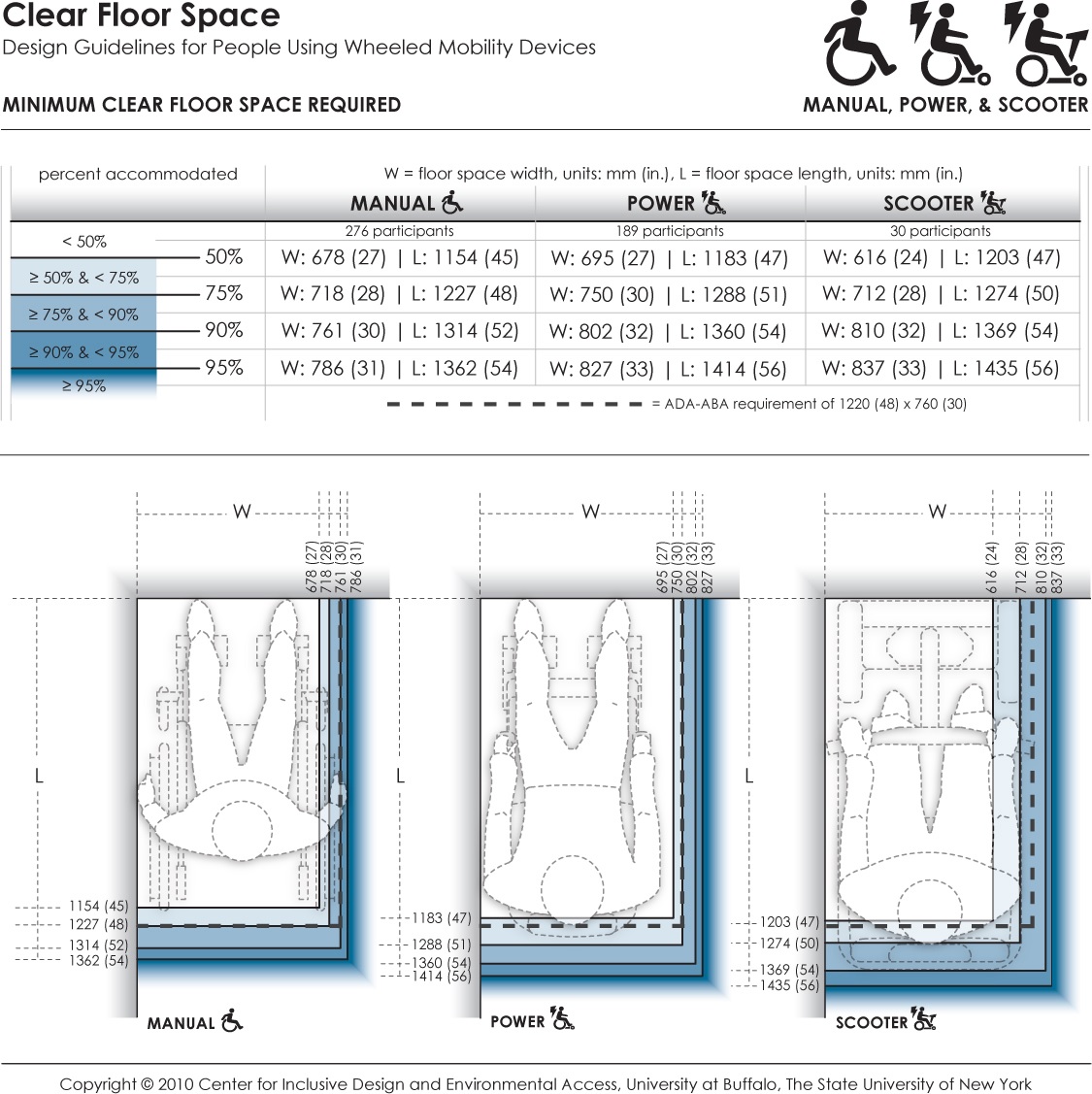
This data provides the minimum dimensions for the rectangular floor area required by occupied wheeled mobility devices (i.e., with the occupant seated in their own wheeled mobility device) when stationary. Clear floor area dimensions are used for determining the size of spaces designated for wheeled mobility users (such as on buses, in movie theaters, sports stadiums). The clear floor area width dimension also informs the minimum clearance width for successful passage through corridors, doorways, and wheelchair ramps. Currently, the ADA accessibility guidelines prescribe a minimum floor area of 760 x 1220 mm (30 x 48 in.) for wheeled mobility access. Dimensions are based on length and width measurements obtained from occupied wheeled mobility devices as part of the Anthropometry of Wheeled Mobility Study. These data suggest minimum clear floor area dimensions of 786 x 1362 mm (31 x 54 in.) for manual chairs, 827 x 1414 mm (33 x 56 in.) for powered chairs, and 837 x 1435 mm (33 x 56 in.) for scooters when needing to accommodate 95% of users.
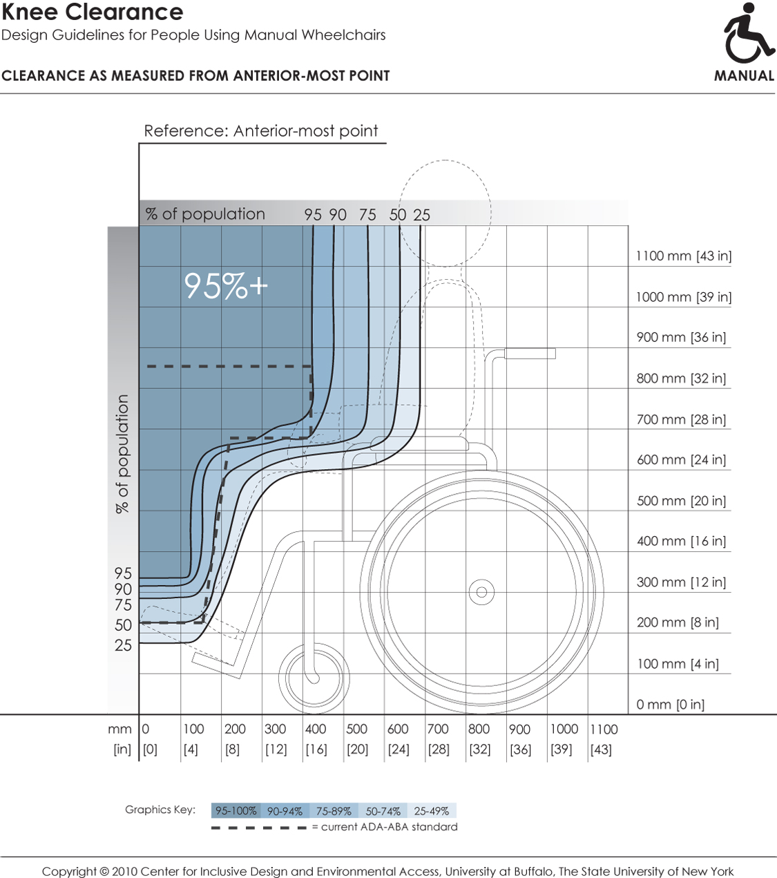
This depicts knee and toe clearance required by manual chair users for forward approach to elements in the built environment (e.g., light switches). It references dimensions of clearance height and depth to the forward-most point on the person or mobility device (e.g., toe, footrest). Shaded areas depict the envelope of space required by the specified percentage of people if positioned with the forward-most point touching the wall. Hence, to accommodate a particular percentage of users, the side profile of a design element (shown by dotted line) should not extend outside the corresponding shaded area.
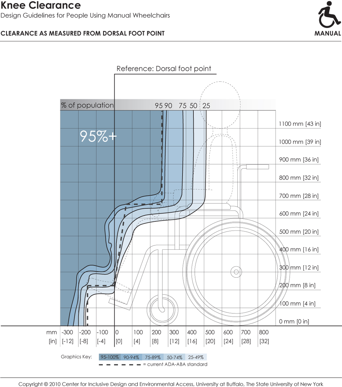
This depicts knee and toe clearance required by manual chair users for forward approach to elements in the built environment (e.g., countertops). It references dimensions of clearance height and depth to the dorsal foot point on a person (e.g., top of ankle). Shaded areas depict the envelope of space required by the specified percentage of people if positioned with the dorsal foot point touching an obstruction. Hence, to accommodate a particular percentage of users, the side profile of a design element (shown by dotted line) should not extend outside the corresponding shaded area.
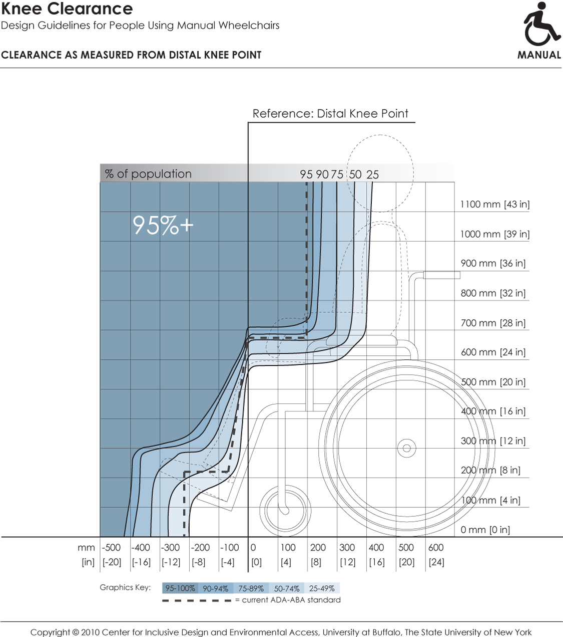
This depicts knee and toe clearance required by manual chair users for forward approach to elements in the built environment (e.g., lavatories, drinking fountains). It references dimensions of clearance height and depth to the distal knee point on a person. Shaded areas depict the envelope of space required by the specified percentage of people if positioned with the distal knee point touching an obstruction. Hence, to accommodate a particular percentage of users, the side profile of a design element (shown by dotted line) should not extend outside the corresponding shaded area.
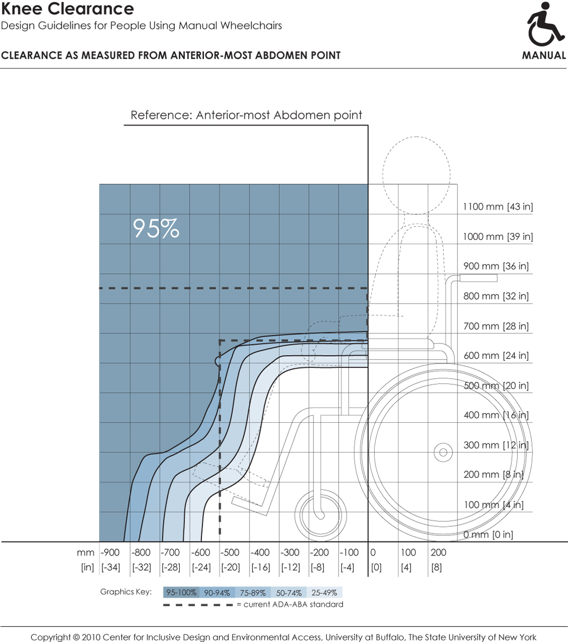
This depicts knee and toe clearance required by manual chair users for forward approach to elements in the built environment (e.g., dining tables). It references dimensions of clearance height and depth to the forward-most abdomen point on a person. Shaded areas depict the envelope of space required by the specified percentage of people if positioned with the abdomen touching an obstruction. Hence, to accommodate a particular percentage of users, the side profile of a design element (shown by dotted line) should not extend outside the corresponding shaded area.
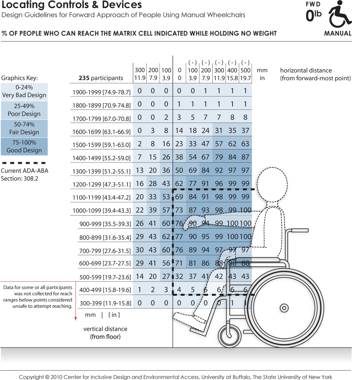
These data depict the reaching abilities of manual chair users represented as the percentage of users expected to reach to a target location in the forward reach direction for a given (a) height from the floor (shown the vertical axis) and (b) offset distance (shown on the horizontal axis) from the forward-most point of the person or wheelchair (e.g., toe, footrest). Horizontal distances in the positive range represent offset distance away from the body (or barrier depth) when reaching over an obstruction in relation to the forward-most point, and the negative range implying that the reach target is brought closer to the person (such as on a table with knee clearance). The percentages are color coded to differentiate regions in reach performance. The dashed lines indicate the current ADA-ABA requirement.
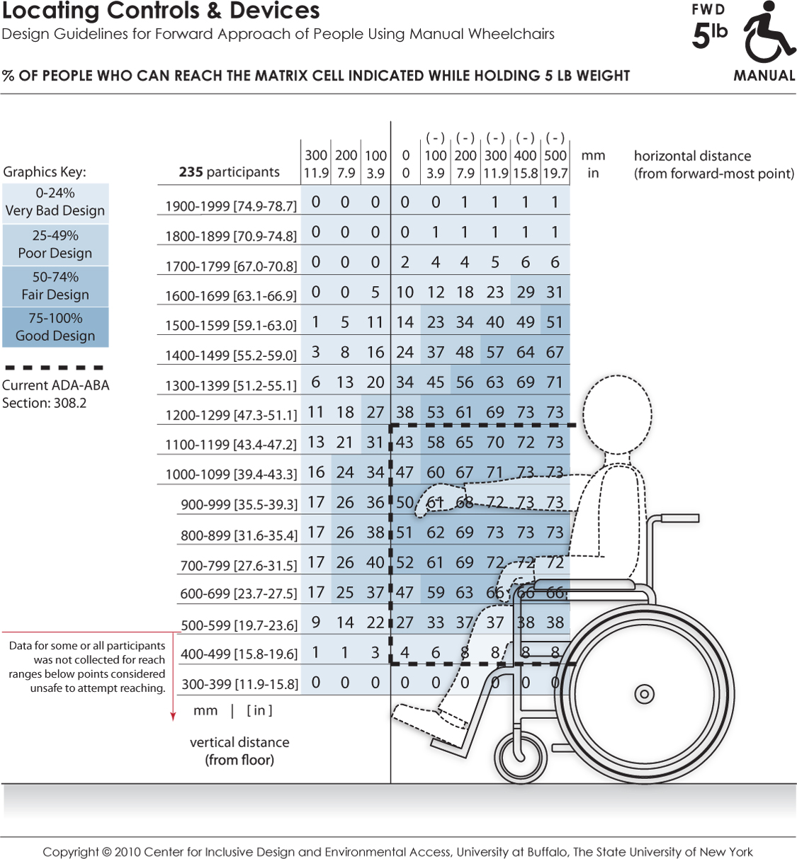
These data depict the reaching abilities of manual chair users represented as the percentage of users able to retrieve and place a 5 lb weight on a target shelf in the forward reach direction for a given (a) height from the floor (shown the vertical axis) and (b) offset distance (shown on the horizontal axis) from the forward-most point of the person or wheelchair (e.g., toe, footrest). Horizontal distances in the positive range represent offset distance away from the body (or barrier depth) when reaching over an obstruction in relation to the forward-most point, and the negative range implying that the reach target is brought closer to the person (such as on a table with knee clearance). The percentages are color coded to differentiate regions in reach performance. The dashed lines indicate the current ADA-ABA requirement.
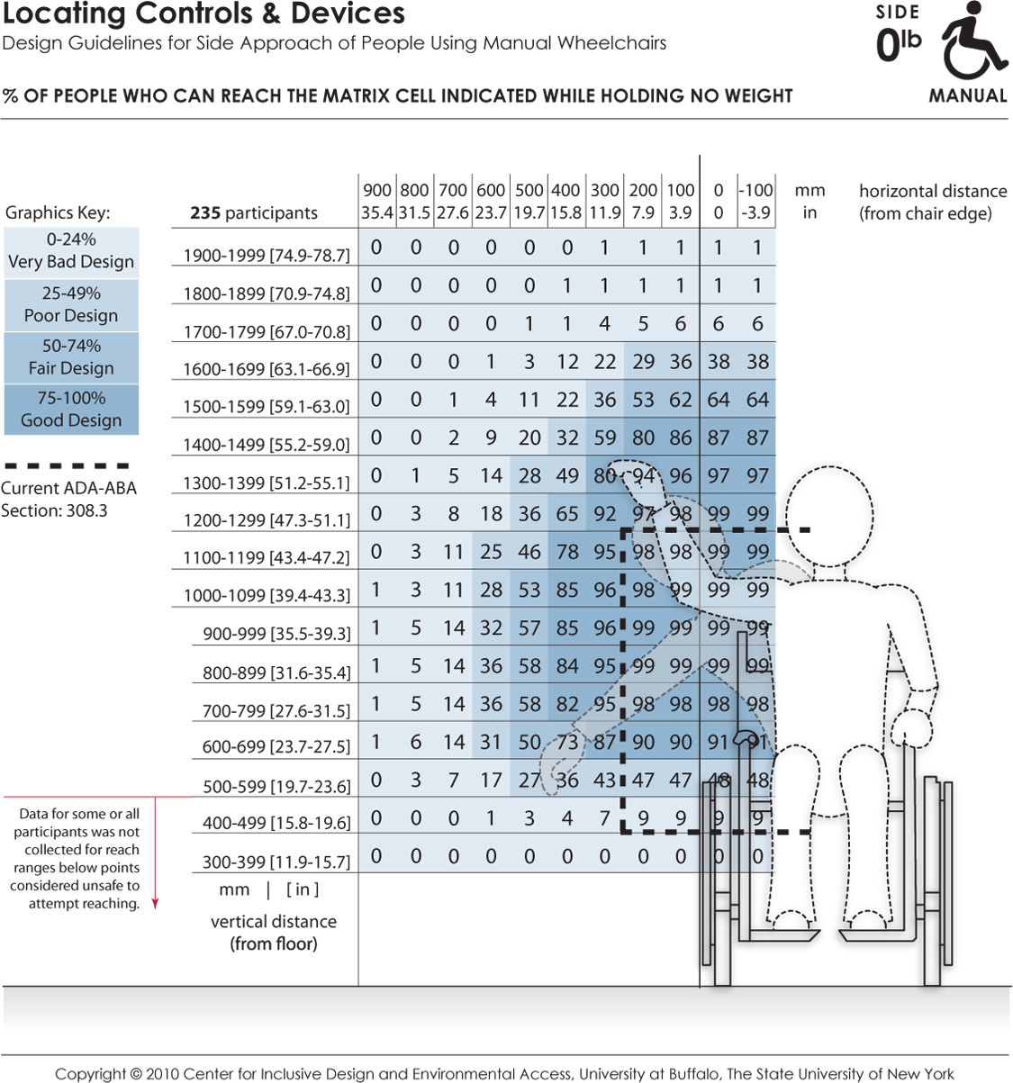
These data depict the reaching abilities of manual chair users represented as the percentage of users expected to reach to a target location in the lateral or sideways reach direction for a given (a) height from the floor (shown the vertical axis) and (b) offset distance (shown on the horizontal axis) from the lateral-most point of the person or wheelchair (e.g., elbow, armrest). Horizontal distances in the positive range represent offset distance away from the body (or barrier depth) in relation to the lateral-most point, and the negative range implying that the reach target is brought closer to the person. The dashed lines indicate the current ADA-ABA requirement.
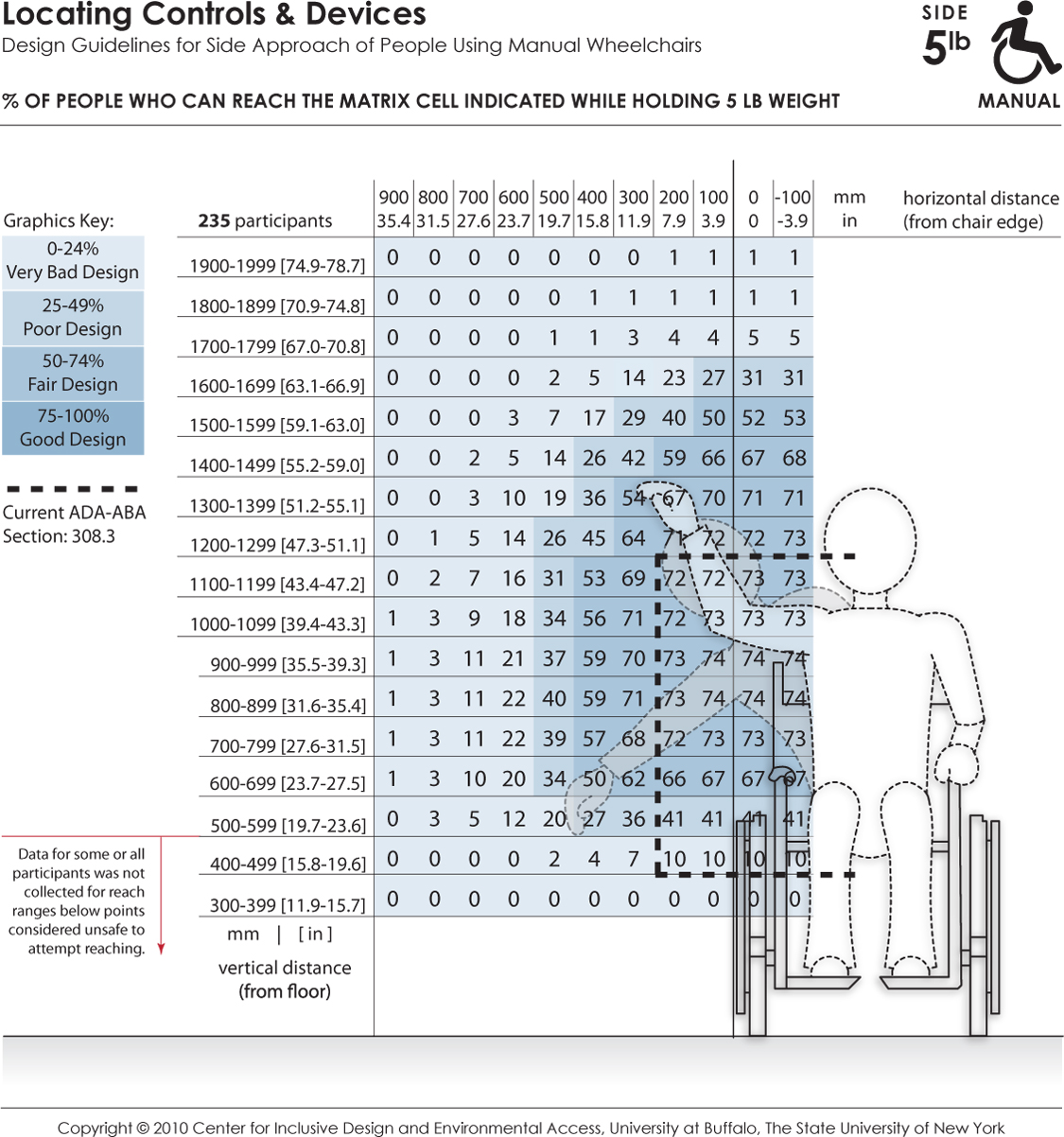
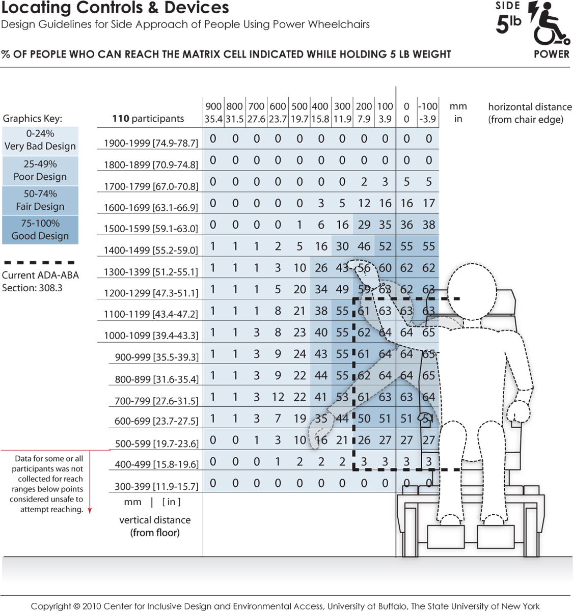
These data depict the reaching abilities of manual chair users represented as the percentage of users able to retrieve and place a 5 lb object on a target shelf in the lateral or sideways reach direction for a given (a) height from the floor (shown the vertical axis) and (b) offset distance (shown on the horizontal axis) from the lateral-most point of the person or wheelchair (e.g., elbow, armrest). Horizontal distances in the positive range represent offset distance away from the body (or barrier depth) in relation to the lateral-most point, and the negative range implying that the reach target is brought closer to the person. The dashed lines indicate the current ADA-ABA requirement.
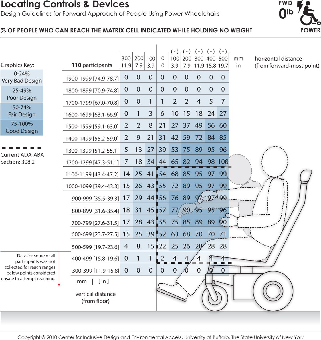
These data depict the reaching abilities of power chair users represented as the percentage of users expected to reach to a target location in the forward reach direction for a given (a) height from the floor (shown the vertical axis) and (b) offset distance (shown on the horizontal axis) from the forward-most point of the person or wheelchair (e.g., toe, footrest). Horizontal distances in the positive range represent offset distance away from the body (or barrier depth) when reaching over an obstruction in relation to the forward-most point, and the negative range implying that the reach target is brought closer to the person (such as on a table with knee clearance). The percentages are color coded to differentiate regions in reach performance. The dashed lines indicate the current ADA-ABA requirement.
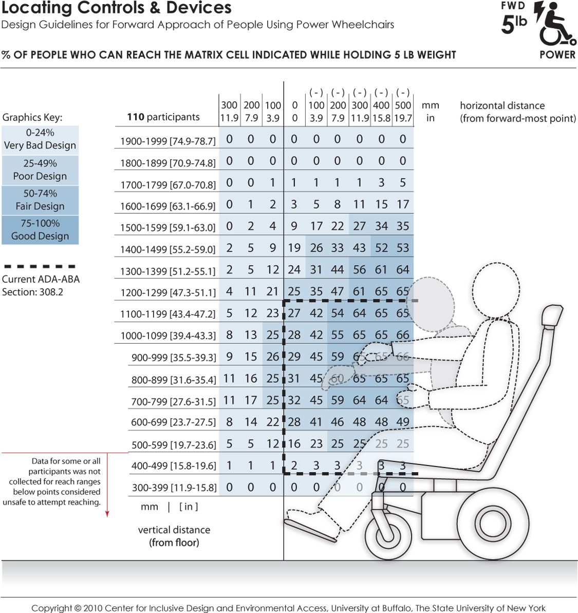
These data depict the reaching abilities of power chair users represented as the percentage of users able to retrieve and place a 5 lb weight on a target shelf in the forward reach direction for a given (a) height from the floor (shown the vertical axis) and (b) offset distance (shown on the horizontal axis) from the forward-most point of the person or wheelchair (e.g., toe, footrest). Horizontal distances in the positive range represent offset distance away from the body (or barrier depth) when reaching over an obstruction in relation to the forward-most point, and the negative range implying that the reach target is brought closer to the person (such as on a table with knee clearance). The percentages are color coded to differentiate regions in reach performance. The dashed lines indicate the current ADA-ABA requirement.
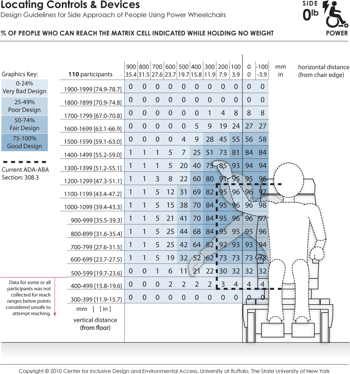
These data depict the reaching abilities of power chair users represented as the percentage of users expected to reach to a target location in the lateral or sideways reach direction for a given (a) height from the floor (shown the vertical axis) and (b) offset distance (shown on the horizontal axis) from the lateral-most point of the person or wheelchair (e.g., elbow, armrest). Horizontal distances in the positive range represent offset distance away from the body (or barrier depth) in relation to the lateral-most point, and the negative range implying that the reach target is brought closer to the person. The dashed lines indicate the current ADA-ABA requirement.
These data depict the reaching abilities of power chair users represented as the percentage of users able to retrieve and place a 5 lb object on a target shelf in the lateral or sideways reach direction for a given (a) height from the floor (shown the vertical axis) and (b) offset distance (shown on the horizontal axis) from the lateral-most point of the person or wheelchair (e.g., elbow, armrest). Horizontal distances in the positive range represent offset distance away from the body (or barrier depth) in relation to the lateral-most point, and the negative range implying that the reach target is brought closer to the person. The dashed lines indicate the current ADA-ABA requirement.
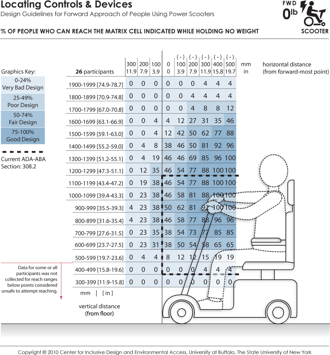
These data depict the reaching abilities of scooter users represented as the percentage of users expected to reach to a target location in the forward reach direction for a given (a) height from the floor (shown the vertical axis) and (b) offset distance (shown on the horizontal axis) from the forward-most point of the person or wheelchair (e.g., toe, footrest). Horizontal distances in the positive range represent offset distance away from the body (or barrier depth) when reaching over an obstruction in relation to the forward-most point, and the negative range implying that the reach target is brought closer to the person (such as on a table with knee clearance). The percentages are color coded to differentiate regions in reach performance. The dashed lines indicate the current ADA-ABA requirement.
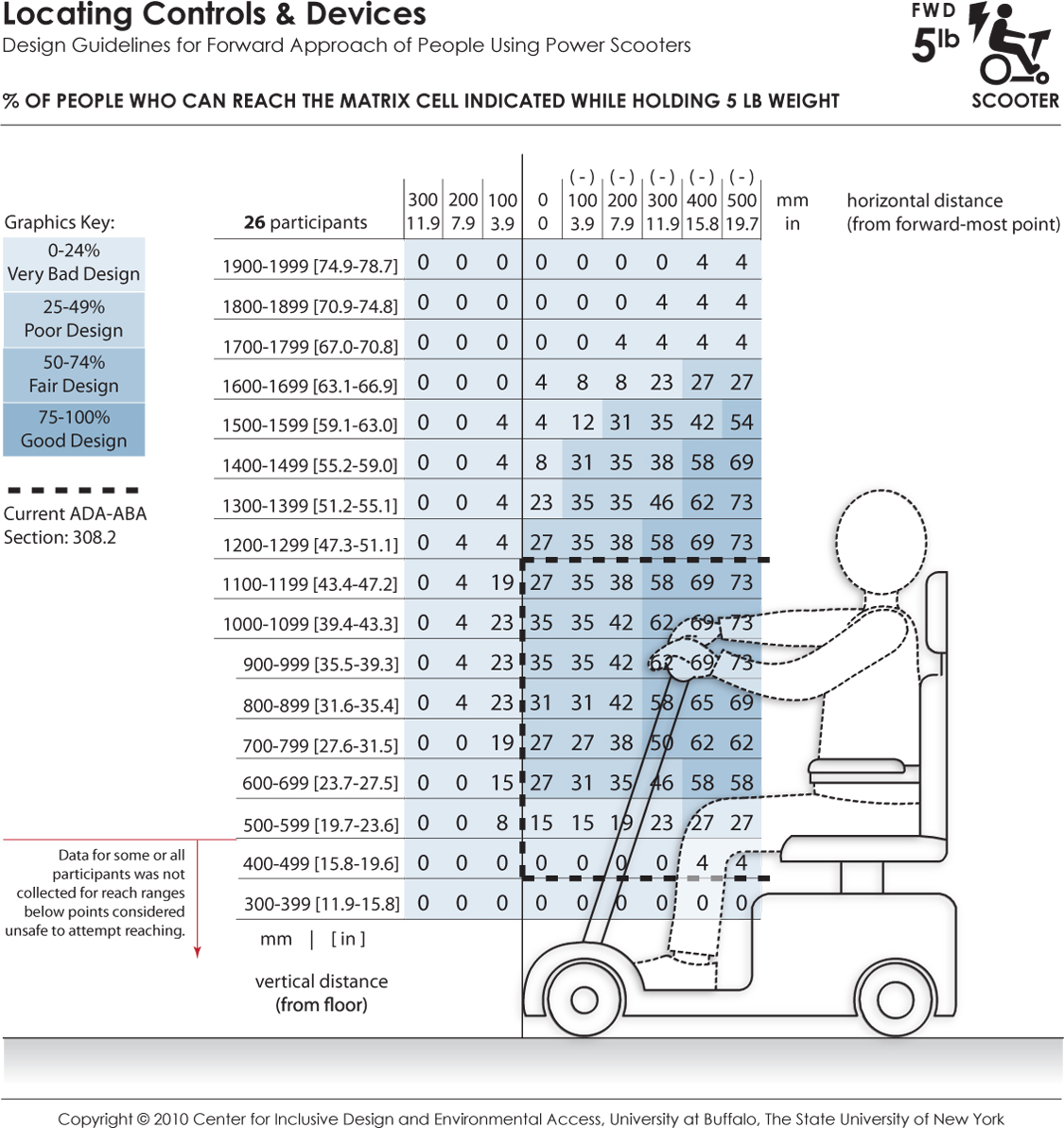
These data depict the reaching abilities of scooter users represented as the percentage of users able to retrieve and place a 5 lb weight on a target shelf in the forward reach direction for a given (a) height from the floor (shown the vertical axis) and (b) offset distance (shown on the horizontal axis) from the forward-most point of the person or wheelchair (e.g., toe, footrest). Horizontal distances in the positive range represent offset distance away from the body (or barrier depth) when reaching over an obstruction in relation to the forward-most point, and the negative range implying that the reach target is brought closer to the person (such as on a table with knee clearance). The percentages are color coded to differentiate regions in reach performance. The dashed lines indicate the current ADA-ABA requirement.
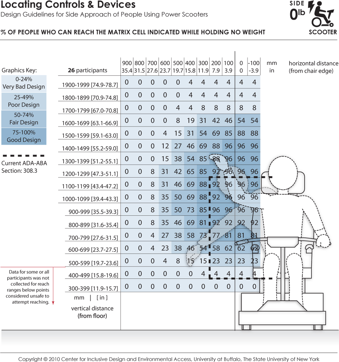
These data depict the reaching abilities of scooter users represented as the percentage of users expected to reach to a target location in the lateral or sideways reach direction for a given (a) height from the floor (shown the vertical axis) and (b) offset distance (shown on the horizontal axis) from the lateral-most point of the person or wheelchair (e.g., elbow, armrest). Horizontal distances in the positive range represent offset distance away from the body (or barrier depth) in relation to the lateral-most point, and the negative range implying that the reach target is brought closer to the person. The dashed lines indicate the current ADA-ABA requirement.
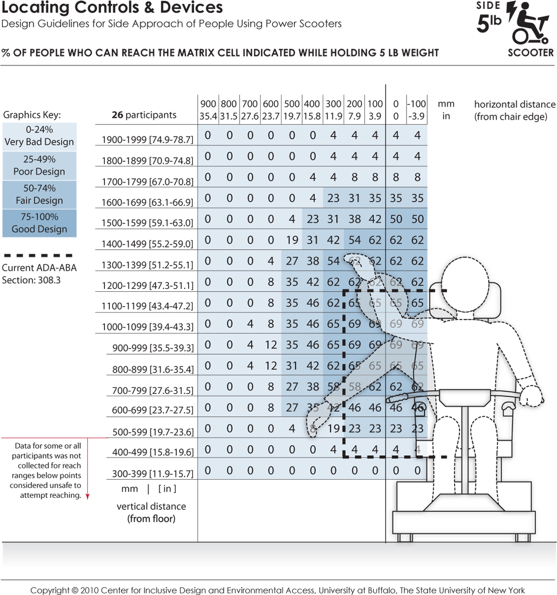
These data depict the reaching abilities of scooter users represented as the percentage of users able to retrieve and place a 5 lb object on a target shelf in the lateral or sideways reach direction for a given (a) height from the floor (shown the vertical axis) and (b) offset distance (shown on the horizontal axis) from the lateral-most point of the person or wheelchair (e.g., elbow, armrest). Horizontal distances in the positive range represent offset distance away from the body (or barrier depth) in relation to the lateral-most point, and the negative range implying that the reach target is brought closer to the person. The dashed lines indicate the current ADA-ABA requirement.
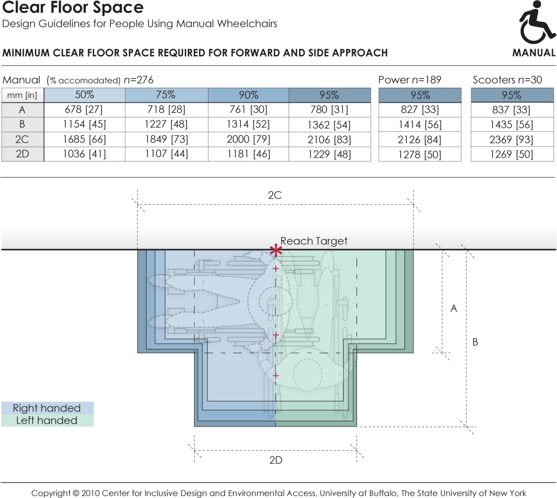
This data depicts the amount of clear floor area required by persons using wheeled mobility devices when performing a forward or side reach to a target location (e.g., reaching to a light switch on the wall) with either the right or left hand. The accompanying table provides dimensions values for clear floor area to accommodate 95% of manual chair (n=276), power chair (n=189), and scooter (n=30) users that were measured as part of the Anthropometry of Wheeled Mobility study. The dimensions of clear floor area are based on four anthropometry dimensions. These dimensions are: (A) occupied width, the horizontal distance between the side-most (lateral-most) points of the wheelchair or occupant on the right and left side; (B) occupied length, the horizontal distance from the front-most (anterior-most) point of the wheelchair or occupant to the rear-most (posterior-most) point of the wheelchair or occupant; (C)the horizontal distance from the reaching shoulder to the front-most (anterior-most) point of the wheelchair or occupant; (D) the horizontal distance from the reaching shoulder to the side-most (lateral-most) point on the opposite (contra-lateral) side of the wheelchair or occupant.
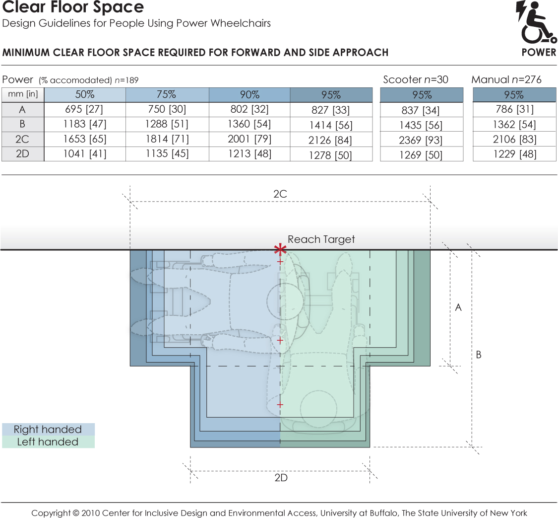
This data depicts the amount of clear floor area required by persons using wheeled mobility devices when performing a forward or side reach to a target location (e.g., reaching to a light switch on the wall) with either the right or left hand. The accompanying table provides dimensions values for clear floor area to accommodate 95% of power chair (n=189), scooter (n=30), and manual chair (n=276), users that were measured as part of the Anthropometry of Wheeled Mobility study. The dimensions of clear floor area are based on four anthropometry dimensions. These dimensions are: (A) occupied width, the horizontal distance between the side-most (lateral-most) points of the wheelchair or occupant on the right and left side; (B) occupied length, the horizontal distance from the front-most (anterior-most) point of the wheelchair or occupant to the rear-most (posterior-most) point of the wheelchair or occupant; (C)the horizontal distance from the reaching shoulder to the front-most (anterior-most) point of the wheelchair or occupant; (D) the horizontal distance from the reaching shoulder to the side-most (lateral-most) point on the opposite (contra-lateral) side of the wheelchair or occupant.
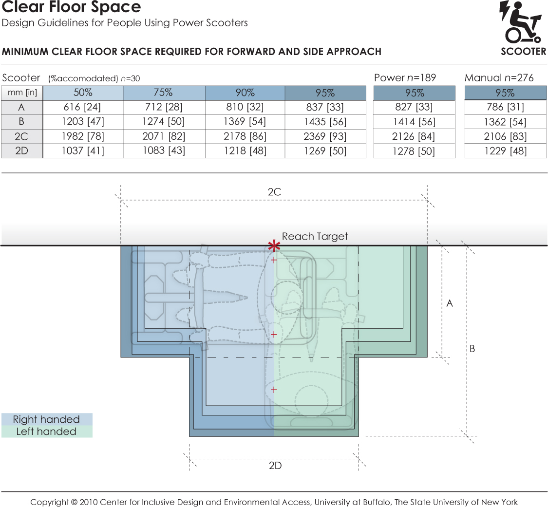
This data depicts the amount of clear floor area required by persons using wheeled mobility devices when performing a forward or side reach to a target location (e.g., reaching to a light switch on the wall) with either the right or left hand. The accompanying table provides dimensions values for clear floor area to accommodate 95% of scooter (n=30), power chair (n=189), and manual chair (n=276) users that were measured as part of the Anthropometry of Wheeled Mobility study. The dimensions of clear floor area are based on four anthropometry dimensions. These dimensions are: (A) occupied width, the horizontal distance between the side-most (lateral-most) points of the wheelchair or occupant on the right and left side; (B) occupied length, the horizontal distance from the front-most (anterior-most) point of the wheelchair or occupant to the rear-most (posterior-most) point of the wheelchair or occupant; (C)the horizontal distance from the reaching shoulder to the front-most (anterior-most) point of the wheelchair or occupant; (D) the horizontal distance from the reaching shoulder to the side-most (lateral-most) point on the opposite (contra-lateral) side of the wheelchair or occupant.
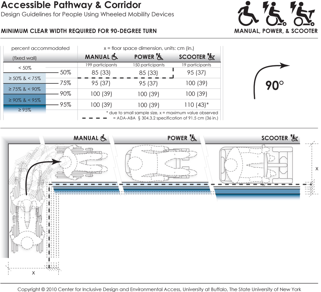
This data depicts the amount of space required by users of wheeled mobility devices to perform a 90-degree turn ("L-Turn"). The bold dashed line in the table and figure indicates the current ADA-ABA requirement of a 91.5 cm (36 in.) passage width. Findings from the Anthropometry of Wheeled Mobility Study indicate that a width of at least 85 cm (33 in.) was required for 50% of the manual and power wheelchair users measured in this study to perform a 90-degree turn. A width of 100 cm (39 in.) was required in order for 95% of manual wheelchair and power chair users to complete the turn, with 95% of scooter users needing a width of at least 110 cm (43 in.) These data are based on measurements of wheeled mobility users performing 90-degree turns in a hallway, built with mock walls. The outside wall of the hallway was fixed. The other side of each leg had moveable walls. The enclosed space was incrementally increased until a user could pass through the turn successfully. The minimum space required to perform a complete 90-degree turn within moving or knocking down any of the walls was recorded. Use of multiple short turns was allowed in contrast to a single continuous turn.
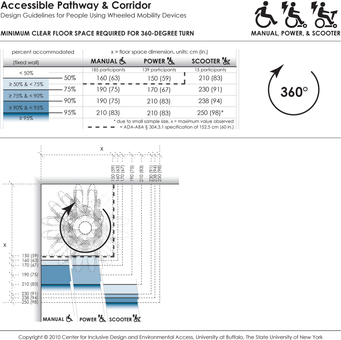
This data depicts the amount of space required by users of wheeled mobility devices to perform a 360-degree turn. The bold dashed line in the table and figure indicates the current ADA-ABA requirement of a 152.5 cm (60 in.) turn space. Findings from the Anthropometry of Wheeled Mobility Study indicate that a square space of at least 160 x 160 cm (63 in.) was required for 50% of the manual wheelchair users measured in this study to perform a 360-degree turn. A space of 210 x 210 cm (83 in.) was required in order for 95% of manual wheelchair and power chair users to complete the turn, with 95% of scooter users needing a space of at least 250 x 250 cm (98 in.) These data are based on measurements of wheeled mobility users performing 360-degree turns within an enclosed square space built with mock walls. The enclosed space was incrementally varied from a size of 130 x 130 cm (51 in.) to 250 x 250 cm (98 in.) The minimum space required to perform a complete 360-degree turn within moving or knocking down any of the walls was recorded. Use of multiple short turns was allowed in contrast to a single continuous turn.
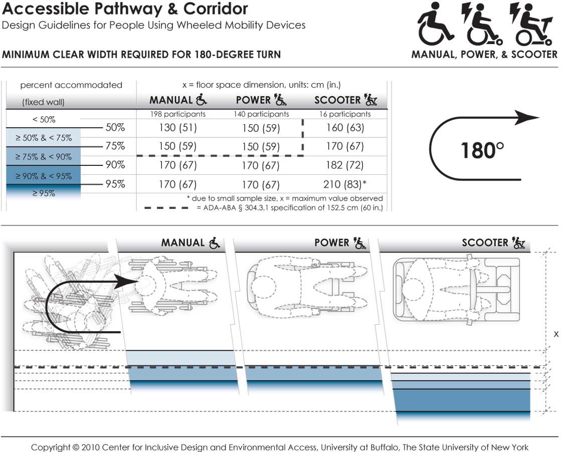
This data depicts the amount of space required by users of wheeled mobility devices to perform a 180-degree turn. The bold dashed line in the table and figure indicates the current ADA-ABA requirement of a 152.5 cm (60 in.) space for wheeled mobility users to turn around. Findings from the Anthropometry of Wheeled Mobility Study indicate that a width of at least 130 cm (51 in.) was required for 50% of the manual wheelchair users measured in this study to perform a 90-degree turn. A width of 170 cm (67 in.) was required in order for 95% of manual wheelchair and power chair users to complete the turn, with 95% of scooter users needing a width of at least 210 cm (83 in.) These data are based on measurements of wheeled mobility users performing 180-degree turns in a dead-end hallway, built with mock walls. The end wall and a second wall of the hallway was fixed. The other side of the hallway had a moveable wall. The hallway width was incrementally increased until a user could enter the space, turn around, and exit the space successfully. The minimum space required to perform a complete 180-degree turn within moving or knocking down any of the walls was recorded. Use of multiple short turns was allowed in contrast to a single continuous turn.
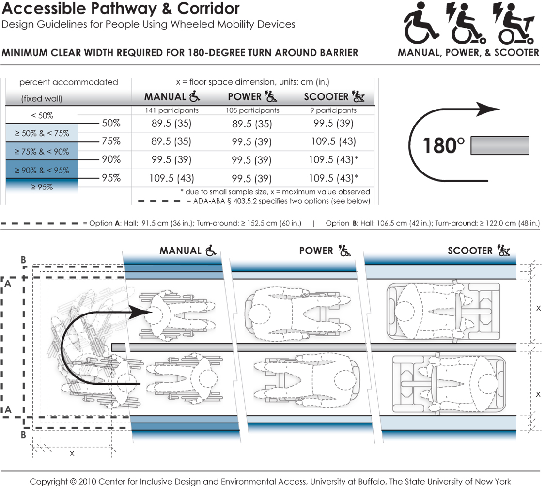
This data depicts the amount of space required by users of wheeled mobility devices to perform a 180-degree turn ("U-Turn") around an obstruction. The bold dashed line in the table and figure indicates the current ADA-ABA requirements, which vary based on the passage width and space available at the base of the turn. Findings from the Anthropometry of Wheeled Mobility Study indicate that a uniform width of at least 89.5 cm (35 in.) was required for 50% of the manual and power wheelchair users measured in this study to perform a 180-degree turn around the obstruction. A width of 109.5 cm (43 in.) was required in order to accommodate 95% of all users. These data are based on measurements of wheeled mobility users performing 180-degree turns around an obstruction, built with mock walls. An obstruction of 11 cm (4 in.) was fixed at a central location. Three moveable walls were constructed around the central fixed wall to form a U-shaped hallway of equal passage width. The enclosed space was incrementally and uniformly increased until a user could pass through the U-turn successfully. The minimum space required to perform a complete 180-degree turn around an obstruction within moving or knocking down any of the walls was recorded. Use of multiple short turns was allowed in contrast to a single continuous turn.
User Comments/Questions
Add Comment/Question