Surfacing the Accessible Playground: 7 Things Every Playground Owner Should Know About the Accessibility of Their Playground Surfaces
4. Assess During the Planning, Installation and Maintenance Phases
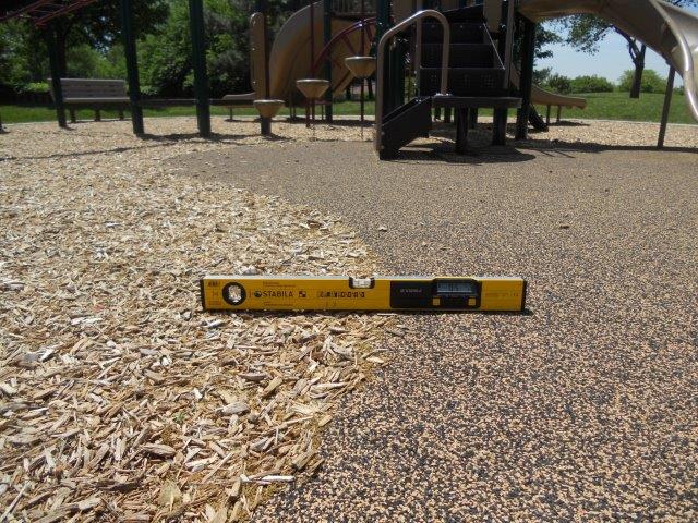
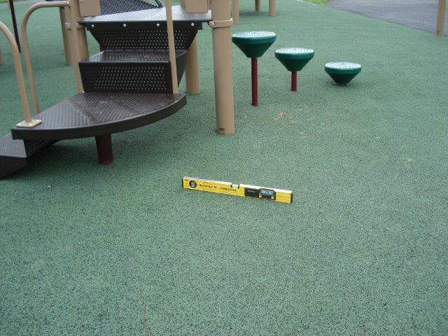
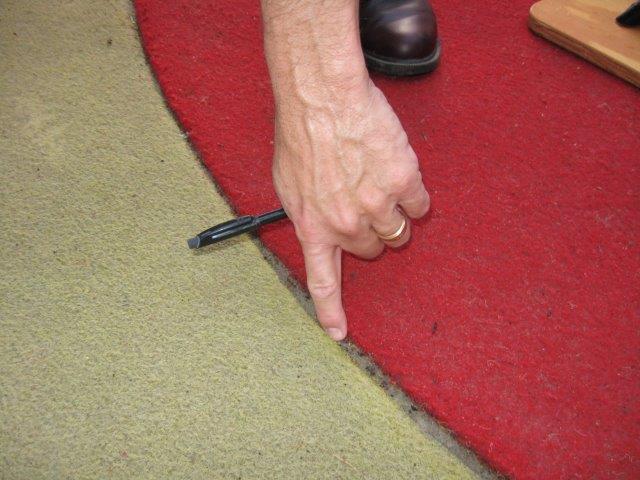
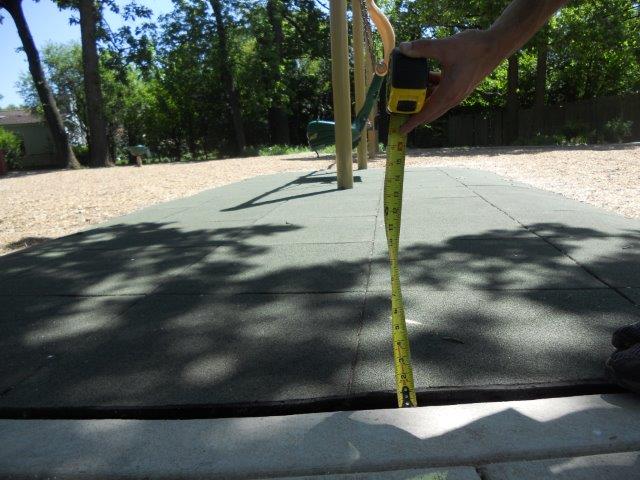
Once the playground surface is installed, an on-site inspection of the surface system should be conducted along the accessible routes, at the clear ground spaces for entry/egress of equipment and required turning spaces. A digital level can be used to measure the running slope and cross slope. A 2 ft. digital level is most commonly used for accessibility assessments as it can measure greater variances within the cross slope than a longer level. A tape measure can be used to check any changes in level and openings on the accessible route. Changes in level should also be checked at transition points where the surface material changes. The firmness and stability of the playground surface along the accessible route can be measured in the field with a Rotational Penetrometer.
Quick Reference
Running slope = 1:16 or 6.25% max
Cross slope = 1:48 or 2.08% max
Changes in level = 1/4 inch max (no bevel)
1/2 inch max (with bevel)
Openings = 1/2 inch max
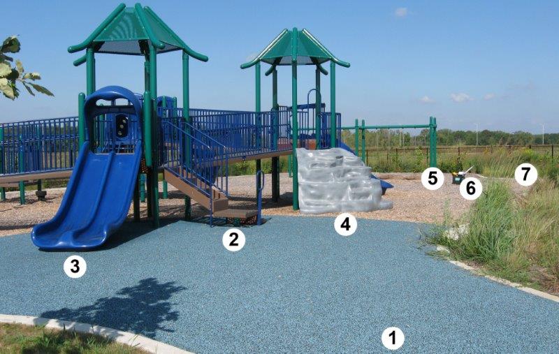
When conducting an assessment of the ground level accessible route, it helps to start with “the big picture” -- to view the play area in its entirety. Begin at the entry to the play area. Identify the accessible play components and the path to entry/egress for each piece of accessible equipment. Then focus in on the accessible route. Each segment of the route should be assessed for compliance with the accessibility standards. Look for the worst areas, those locations where the slope or cross slope may exceed the standard, where changes in level may be too high, or where openings may be too large.
One method to assess the ground level route using the photo above would be to look at each route segment, such as:
- From the entry of the play area where the surface begins to the transfer system at the composite play structure.
- The clear ground space at the transfer system.
- Segments at each accessible elevated component egress to ground level, the clear ground space at egress, and the connector loop back to the transfer system, such as the segment from the right of the double slide and the clear ground space at the bottom of the slide to the transfer system; and
- The segment to the right of the transfer system to the climbing wall including the transition from the poured in place surface to the engineered wood fiber and the clear ground space at the climber.
- The segments from the entry and composite structure to the swings, including the clear ground space at a swing.
- Segments to each accessible ground level play component.
- Segments to other accessible play areas.
The purpose here is to look for deficiencies in order to make corrective actions. All of the technical provisions must be met through the entire route for it to be considered accessible. Thus, each segment should be assessed for slope, cross slope, change in level, openings, firmness and stability (which will be discussed in greater detail in the next sections). It would be inaccurate and incomplete to only measure slope at one segment, cross slope at another, or to average the data for three segments. Every segment of a route is used by people with disabilities, therefore it is critical that each segment meet the minimum standards.
Measuring Up: Playground Surface Field Testing
Regular inspections of the playground surface and equipment should be conducted to ensure continued safety and accessibility for all users. These inspections should include safety checks, the accessibility assessment of the accessible route, and field testing of the playground surface. Field testing conducted on the playground surface in the use zone should measure the impact attenuation for children who may fall, along with firmness and stability for accessibility to people with disabilities. This field testing should be conducted upon installation and throughout the life cycle of the playground. The Accessibility Standards require the accessible route within the play area comply with two referenced ASTM standards: ASTM F1951-99 Standard Specification for Determination of Accessibility of Surface Systems Under and Around Playground Equipment; and ASTM F1292-99/04 Standard Specification for Impact Attenuation of Surface Systems Under and Around Playground Equipment.
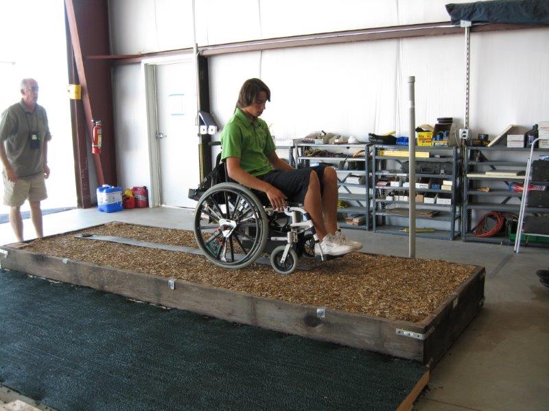
ASTM F1951-99: Lab Test
This is a laboratory test measuring the work force required for a 165 (+11 or -4.4) lb. individual in a manual wheelchair to propel across a given surface.
The lab test uses a 7 percent ramp as a baseline for the wheelchair rider. After the baseline is established, the rider conducts a series of straight propulsions over the sample surface for a minimum distance of 6.56 ft. The force needed to propel the wheelchair rider over the surface is measured. A second series of tests are then run where the wheelchair rider makes a 90 degree turn and the force is measured again. If the average work per foot for the sample surface is less than the work force to propel up the 7 percent ramp, the surface sample is considered as passing ASTM F1951-99. The advantage of the ASTM F1951-99 test procedure is that it provides a starting point to compare various surfaces by an objective measurement. However, the primary disadvantage and criticism of the protocol is that it is designed as a lab test in a controlled environment and cannot be easily replicated in the field or outdoors at multiple playground sites. Researchers have attempted to address the portability of this test protocol with the development of the Rotational Penetrometer (RP) described below.
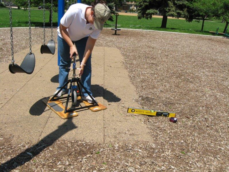
Firmness and Stability: Field Test
While the ASTM F1951-99 protocol does not include a procedure for field testing outdoors at a playground, a field test method has been developed by the same engineering company that developed the original lab test method. A portable instrument known as a Rotational Penetrometer (RP) has been designed to measure the firmness and stability of surfaces. For the purpose of the NCA study, the Rotational Penetrometer was used as the field instrument to measure firmness and stability in lieu of the costly equipment for ASTM F1951-99. Documented research has shown the Rotational Penetrometer to have a high degree of repeatability and reproducibility (ASTM, May 27, 2005; ASTM, September 2010). These research findings also correlate to the lab test.
The RP design includes a wheelchair caster placed on a spring loaded caliber in a metal tripod frame which suspends the caster about 6 inches over the surface. When the caster is released, the spring load gauge replicates the force of an individual in a wheelchair over a given surface. The penetration into the surfaces is measured for readings of “firmness” and “stability.” National experts recognize the use of the Rotational Penetrometer as a portable and relatively easy device to use for surface testing. The field test method with the RP can be added to the assessment process just as measurements for slope, cross slope, change in level and openings are taken along segments of the accessible route for the play area. The RP can measure those segments for firmness and stability. This can be valuable in assessing how an installed surface performs over time.
Impact Attenuation: Lab & Field Test
In the field, ASTM F1292-99/04 Standard Specification for Impact Attenuation of Surface Systems Under and Around Playground Equipment is also known as the “head drop test.” It is a test to make sure the surface is resilient enough to prevent a life-threatening injury from a fall. A 6 inch diameter aluminum hemisphere in the shape of a child’s head is dropped from the top of a tripod based on the fall height of play components. The aluminum hemisphere, or missile as it is called, contains an accelerometer. When dropped, the impact attenuation of the surface is measured in G-max and by the Head Injury Criteria (HIC). G-max is a measurement of the maximum acceleration, while HIC measures an integral of the acceleration time. The maximum values allowable by the standard are 200 for G-max and 1,000 for HIC. A TRIAX is the instrument used to conduct this test in the field.
User Comments/Questions
Add Comment/Question