36 CFR Part 1190, Proposed Accessibility Guidelines for Pedestrian Facilities in the Public Right-of-Way: Notice of Proposed Rulemaking (NPRM)
CHAPTER R3: TECHNICAL REQUIREMENTS
R301 General
R301.1 Scope. The technical requirements in Chapter 3 shall apply where required by Chapter 2 or where referenced by a requirement in this document.
R302 Pedestrian Access Routes
R302.1 General. Pedestrian access routes shall comply with R302.
R302.2 Components. Pedestrian access routes shall consist of one or more of the following components:
1. Sidewalks and other pedestrian circulation paths, or a portion of sidewalks and other pedestrian circulation paths, complying with R302.3 through R302.7;
2. Pedestrian street crossings and at-grade rail crossings complying with R302.3 through R302.7, and R306;
3. Pedestrian overpasses and underpasses and similar structures complying with R302.3 through R302.7;
4. Curb ramps and blended transitions complying with R302.7 and R304;
5. Ramps complying with R407;
6. Elevators and limited use/limited application elevators complying with sections 407 or 408 of Appendix D to 36 CFR part 1191;
7. Platform lifts complying with section 410 of Appendix D to 36 CFR part 1191; and
8. Doors, doorways, and gates complying with section 404 of Appendix D to 36 CFR part 1191.
R302.3 Continuous Width. Except as provided in R302.3.1, the continuous clear width of pedestrian access routes shall be 1.2 m (4.0 ft) minimum, exclusive of the width of the curb.
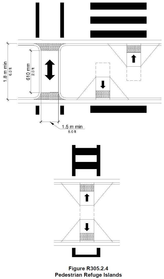
R302.3.1 Medians and Pedestrian Refuge Islands. The clear width of pedestrian access routes within medians and pedestrian refuge islands shall be 1.5 m (5.0 ft) minimum.
R302.4 Passing Spaces. Where the clear width of pedestrian access routes is less than 1.5 m (5.0 ft), passing spaces shall be provided at intervals of 61 m (200.0 ft) maximum. Passing spaces shall be 1.5 m (5.0 ft) minimum by 1.5 m (5.0 ft) minimum. Passing spaces are permitted to overlap pedestrian access routes.
R302.5 Grade. Except as provided in R302.5.1, where pedestrian access routes are contained within a street or highway right-of-way, the grade of pedestrian access routes shall not exceed the general grade established for the adjacent street or highway. Where pedestrian access routes are not contained within a street or highway right-of-way, the grade of pedestrian access routes shall be 5 percent maximum.
R302.5.1 Pedestrian Street Crossings. Where pedestrian access routes are contained within pedestrian street crossings, the grade of the pedestrian access route shall be 5 percent maximum
R302.6 Cross Slope. Except as provided in R302.6.1 and R302.6.2, the cross slope of pedestrian access routes shall be 2 percent maximum.
R302.6.1 Pedestrian Street Crossings Without Yield or Stop Control. Where pedestrian access routes are contained within pedestrian street crossings without yield or stop control, the cross slope of the pedestrian access route shall be 5 percent maximum.
R302.6.2 Midblock Pedestrian Street Crossings. Where pedestrian access routes are contained within midblock pedestrian street crossings, the cross slope of the pedestrian access route shall be permitted to equal the street or highway grade.
R302.7 Surfaces. The surfaces of pedestrian access routes and elements and spaces required to comply with R302.7 that connect to pedestrian access routes shall be firm, stable, and slip resistant and shall comply with R302.7.
Advisory R302.7 Surfaces. The surface requirements in R302.7 apply to sidewalks and other pedestrian circulation paths, pedestrian street crossings and at-grade rail crossings, pedestrian overpasses and underpasses and similar structures, and curb ramps and blended transitions (see R302.2). The surface requirements in R302.7 also apply to surfaces at the following accessible elements and spaces that connect to pedestrian access routes:
• Clear spaces (see R404.2), including clear spaces at operable parts (see R403.2) such as accessible pedestrian signals and pedestrian pushbuttons (see R209), clear spaces at street furniture such as benches (see R212.6), and clear spaces within transit shelters (see R308.2);
• Boarding and alighting areas and boarding platforms at transit stops (see R308.1.3.1);
• Access aisles at accessible parking spaces (see R309.2.1 and R309.3) and accessible passenger loading zones (see R310.3.4); and ramp runs and landings (see R407.7).
R302.7.1 Vertical Alignment. Vertical alignment shall be generally planar within pedestrian access routes (including curb ramp runs, blended transitions, turning spaces, and gutter areas within pedestrian access routes) and surfaces at other elements and spaces required to comply with R302.7 that connect to pedestrian access routes. Grade breaks shall be flush. Where pedestrian access routes cross rails at grade, the pedestrian access route surface shall be level and flush with the top of rail at the outer edges of the rails, and the surface between the rails shall be aligned with the top of rail.
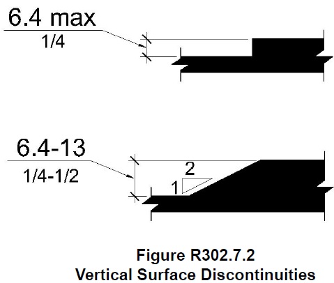
R302.7.2 Vertical Surface Discontinuities. Vertical surface discontinuities shall be 13 mm (0.5 in) maximum. Vertical surface discontinuities between 6.4 mm (0.25 in) and 13 mm (0.5 in) shall be beveled with a slope not steeper than 50 percent. The bevel shall be applied across the entire vertical surface discontinuity.
R302.7.3 Horizontal Openings. Horizontal openings in gratings and joints shall not permit passage of a sphere more than 13 mm (0.5 in) in diameter. Elongated openings in gratings shall be placed so that the long dimension is perpendicular to the dominant direction of travel.
R302.7.4 Flangeway Gaps. Flangeway gaps at pedestrian at-grade rail crossings shall be 64 mm (2.5 in) maximum on non-freight rail track and 75 mm (3 in) maximum on freight rail track.
R303 Alternate Pedestrian Access Routes (See R205)
R304 Curb Ramps and Blended Transitions
R304.1 General. Curb ramps and blended transitions shall comply with R304.
Advisory R304.1 General. There are two types of curb ramps:
• Perpendicular curb ramps have a running slope that cuts through or is built up to the curb at right angles or meets the gutter break at right angles where the curb is curved. On large corner radiuses, it will be necessary to indent the gutter break on one side of the curb ramp in order for the curb ramp to meet the gutter break at right angles.
• Parallel curb ramps have a running slope that is in-line with the direction of sidewalk travel and lower the sidewalk to a level turning space where a turn is made to enter the pedestrian street crossing.
Advisory R304.1 General (continued). Perpendicular curb ramps can be provided where the sidewalk is at least 3.7 m (12.0 ft) wide. Parallel curb ramps can be provided where the sidewalk is at least 1.2 m (4.0 ft) wide. Parallel and perpendicular curb ramps can be combined. A parallel curb ramp is used to lower the sidewalk to a mid-landing and a short perpendicular curb ramp connects the landing to the street. Combination curb ramps can be provided where the sidewalk is at least 1.8 m (6.0 ft) wide. Blended transitions are raised pedestrian street crossings, depressed corners, or similar connections between pedestrian access routes at the level of the sidewalk and the level of the pedestrian street crossing that have a grade of 5 percent or less. Blended transitions are suitable for a range of sidewalk conditions.
R304.2 Perpendicular Curb Ramps. Perpendicular curb ramps shall comply with R304.2 and R304.5.
R304.2.1 Turning Space. A turning space 1.2 m (4.0 ft) minimum by 1.2 m (4.0 ft) minimum shall be provided at the top of the curb ramp and shall be permitted to overlap other turning spaces and clear spaces. Where the turning space is constrained at the back-of-sidewalk, the turning space shall be 1.2 m (4.0 ft) minimum by 1.5 m (5.0 ft) minimum. The 1.5 m (5.0 ft) dimension shall be provided in the direction of the ramp run.
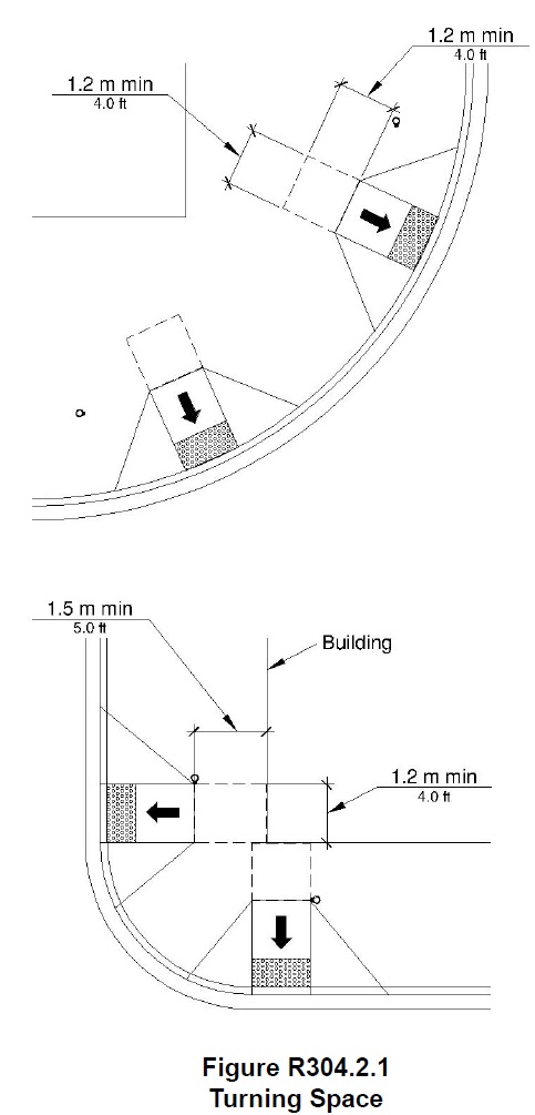
R304.2.2 Running Slope. The running slope of the curb ramp shall cut through or shall be built up to the curb at right angles or shall meet the gutter grade break at right angles where the curb is curved. The running slope of the curb ramp shall be 5 percent minimum and 8.3 percent maximum but shall not require the ramp length to exceed 4.5 m (15.0 ft). The running slope of the turning space shall be 2 percent maximum.
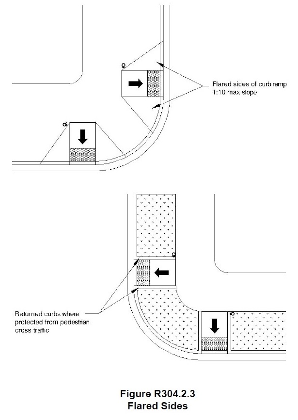
R304.2.3 Flared Sides. Where a pedestrian circulation path crosses the curb ramp, flared sides shall be sloped 10 percent maximum, measured parallel to the curb line.
R304.3 Parallel Curb Ramps. Parallel curb ramps shall comply with R304.3 and R304.5.
R304.3.1 Turning Space. A turning space 1.2 m (4.0 ft) minimum by 1.2 m (4.0 ft) minimum shall be provided at the bottom of the curb ramp and shall be permitted to overlap other turning spaces and clear spaces. If the turning space is constrained on 2 or more sides, the turning space shall be 1.2 m (4.0 ft) minimum by 1.5 m (5.0 ft). The 1.5 m (5.0 ft) dimension shall be provided in the direction of the pedestrian street crossing.
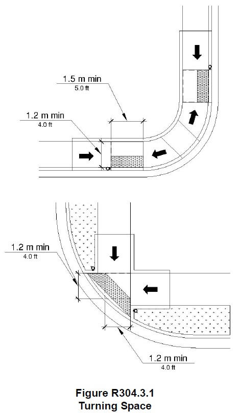
R304.3.2 Running Slope. The running slope of the curb ramp shall be in-line with the direction of sidewalk travel. The running slope of the curb ramp shall be 5 percent minimum and 8.3 percent maximum but shall not require the ramp length to exceed 4.5 m (15.0 ft) minimum. The running slope of the turning space shall be 2 percent maximum.
R304.4 Blended Transitions. Blended transitions shall comply with R304.4 and R304.5.
R304.4.1 Running Slope. The running slope of blended transitions shall be 5 percent maximum.
R304.5 Common Requirements. Curb ramps and blended transitions shall comply with R304.5.
R304.5.1 Width. The clear width of curb ramp runs (excluding any flared sides), blended transitions, and turning spaces shall be 1.2 m (4.0 ft) minimum.
R304.5.2 Grade Breaks. Grade breaks at the top and bottom of curb ramp runs shall be perpendicular to the direction of the ramp run. Grade breaks shall not be permitted on the surface of ramp runs and turning spaces. Surface slopes that meet at grade breaks shall be flush.
R304.5.3 Cross Slope. The cross slope of curb ramps, blended transitions, and turning spaces shall be 2 percent maximum. At pedestrian street crossings without yield or stop control and at midblock pedestrian street crossings, the cross slope shall be permitted to equal the street or highway grade.
R304.5.4 Counter Slope. The counter slope of the gutter or street at the foot of curb ramp runs, blended transitions, and turning spaces shall be 5 percent maximum.
R304.5.5 Clear Space. Beyond the bottom grade break, a clear space 1.2 m (4.0 ft) minimum by 1.2 m (4.0 ft) minimum shall be provided within the width of the pedestrian street crossing and wholly outside the parallel vehicle travel lane.
R305 Detectable Warning Surfaces
R305.1 General. Detectable warning surfaces shall consist of truncated domes aligned in a square or radial grid pattern and shall comply with R305.
R305.1.1 Dome Size. The truncated domes shall have a base diameter of 23 mm (0.9 in) minimum and 36 mm (1.4 in) maximum, a top diameter of 50 percent of the base diameter minimum and 65 percent of the base diameter maximum, and a height of 5 mm (0.2 in).
R305.1.2 Dome Spacing. The truncated domes shall have a center-to-center spacing of 41 mm (1.6 in) minimum and 61 mm (2.4 in) maximum, and a base-to-base spacing of 17 mm (0.65 in) minimum, measured between the most adjacent domes.
R305.1.3 Contrast. Detectable warning surfaces shall contrast visually with adjacent gutter, street or highway, or pedestrian access route surface, either light-on-dark or dark-on-light.
R305.1.4 Size. Detectable warning surfaces shall extend 610 mm (2.0 ft) minimum in the direction of pedestrian travel. At curb ramps and blended transitions, detectable warning surfaces shall extend the full width of the ramp run (excluding any flared sides), blended transition, or turning space. At pedestrian at-grade rail crossings not located within a street or highway, detectable warnings shall extend the full width of the crossing. At boarding platforms for buses and rail vehicles, detectable warning surfaces shall extend the full length of the public use areas of the platform. At boarding and alighting areas at sidewalk or street level transit stops for rail vehicles, detectable warning surfaces shall extend the full length of the transit stop.
R305.2 Placement.
The placement of detectable warning surfaces shall comply with R305.2.
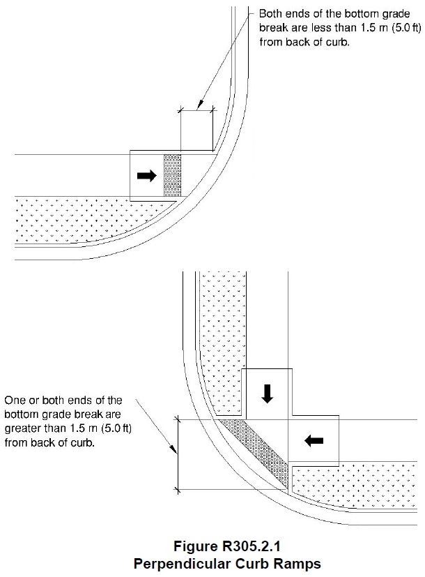
R305.2.1 Perpendicular Curb Ramps. On perpendicular curb ramps, detectable warning surfaces shall be placed as follows:
1. Where the ends of the bottom grade break are in front of the back of curb, detectable warning surfaces shall be placed at the back of curb.
2. Where the ends of the bottom grade break are behind the back of curb and the distance from either end of the bottom grade brake to the back of curb is 1.5 m (5.0 ft) or less, detectable warning surfaces shall be placed on the ramp run within one dome spacing of the bottom grade break.
3. Where the ends of the bottom grade break are behind the back of curb and the distance from either end of the bottom grade brake to the back of curb is more than 1.5 m (5.0 ft), detectable warning surfaces shall be placed on the lower landing at the back of curb.
R305.2.2 Parallel Curb Ramps. On parallel curb ramps, detectable warning surfaces shall be placed on the turning space at the flush transition between the street and sidewalk.
R305.2.3 Blended Transitions. On blended transitions, detectable warning surfaces shall be placed at the back of curb. Where raised pedestrian street crossings, depressed corners, or other level pedestrian street crossings are provided, detectable warning surfaces shall be placed at the flush transition between the street and the sidewalk.
R305.2.4 Pedestrian Refuge Islands. At cut-through pedestrian refuge islands, detectable warning surfaces shall be placed at the edges of the pedestrian island and shall be separated by a 610 mm (2.0 ft) minimum length of surface without detectable warnings.
R305.2.5 Pedestrian At-Grade Rail Crossings. At pedestrian at-grade rail crossings not located within a street or highway, detectable warning surfaces shall be placed on each side of the rail crossing. The edge of the detectable warning surface nearest the rail crossing shall be 1.8 m (6.0 ft) minimum and 4.6 m (15.0 ft) maximum from the centerline of the nearest rail. Where pedestrian gates are provided, detectable warning surfaces shall be placed on the side of the gates opposite the rail.
R305.2.6 Boarding Platforms. At boarding platforms for buses and rail vehicles, detectable warning surfaces shall be placed at the boarding edge of the platform.
R305.2.7 Boarding and Alighting Areas. At boarding and alighting areas at sidewalk or street level transit stops for rail vehicles, detectable warning surfaces shall be placed at the side of the boarding and alighting area facing the rail vehicles.
R306 Pedestrian Street Crossings
R306.1 General. Pedestrian street crossings shall comply with R306.
R306.2 Pedestrian Signal Phase Timing. All pedestrian signal phase timing shall comply with section 4E.06 of the MUTCD (incorporated by reference, see R104.2) and shall be based on a pedestrian clearance time that is calculated using a pedestrian walking speed of 1.1 m/s (3.5 ft/s) or less.
R306.3 Roundabouts. Where pedestrian facilities are provided at roundabouts, they shall comply with R306.3.
R306.3.1 Separation. Where sidewalks are flush against the curb and pedestrian street crossing is not intended, a continuous and detectable edge treatment shall be provided along the street side of the sidewalk. Detectable warning surfaces shall not be used for edge treatment. Where chains, fencing, or railings are used for edge treatment, they shall have a bottom edge 380 mm (15 in) maximum above the sidewalk.
R306.3.2 Pedestrian Activated Signals. At roundabouts with multi-lane pedestrian street crossings, a pedestrian activated signal complying with R209 shall be provided for each multi-lane segment of each pedestrian street crossing, including the splitter island. Signals shall clearly identify which pedestrian street crossing segment the signal serves.
R306.4 Channelized Turn Lanes at Roundabouts. At roundabouts with pedestrian street crossings, pedestrian activated signals complying with R209 shall be provided at pedestrian street crossings at multi-lane channelized turn lanes.
R306.5 Channelized Turn Lanes at Other Signalized Intersections. At signalized intersections other than roundabouts with pedestrian street crossings, pedestrian activated signals complying with R209 shall be provided at pedestrian street crossings at multi-lane channelized turn lanes.
R307 Accessible Pedestrian Signals and Pedestrian Pushbuttons (See R209)
R308 Transit Stops and Transit Shelters
R308.1 Transit Stops. Transit stops shall comply with R308.1.
R308.1.1 Boarding and Alighting Areas. Boarding and alighting areas at sidewalk or street level transit stops shall comply with R308.1.1 and R308.1.3. Where transit stops serve vehicles with more than one car, boarding and alighting areas serving each car shall comply with R308.1.1 and R308.1.3.
R308.1.1.1 Dimensions. Boarding and alighting areas shall provide a clear length of 2.4 m (8.0 ft) minimum, measured perpendicular to the curb or street or highway edge, and a clear width of 1.5 m (5.0 ft) minimum, measured parallel to the street or highway.
R308.1.1.2 Grade. Parallel to the street or highway, the grade of boarding and alighting areas shall be the same as the street or highway, to the extent practicable. Perpendicular to the street or highway, the grade of boarding and alighting areas shall not be steeper than 2 percent.
R308.1.2 Boarding Platforms. Boarding platforms at transit stops shall comply with R308.1.2 and R308.1.3.
R308.1.2.1 Platform and Vehicle Floor Coordination. Boarding platforms shall be positioned to coordinate with vehicles in accordance with the applicable requirements in 49 CFR parts 37 and 38.
R308.1.2.2 Slope. Boarding platforms shall not exceed a slope of 2 percent in any direction. Where boarding platforms serve vehicles operating on existing track or existing street or highway, the slope of the platform parallel to the track or the street or highway is permitted to be equal to the grade of the track or street or highway.
R308.1.3 Common Requirements. Boarding and alighting areas and boarding platforms shall comply with R308.1.3.
R308.1.3.1 Surfaces. The surfaces of boarding and alighting areas and boarding platforms shall comply with R302.7.
R308.1.3.2 Connection. Boarding and alighting areas and boarding platforms shall be connected to streets, sidewalks, or pedestrian circulation paths by pedestrian access routes complying with R302.
R308.2 Transit Shelters. Transit shelters shall be connected by pedestrian access routes complying with R302 to boarding and alighting areas or boarding platforms complying with R308.1. Transit shelters shall provide a minimum clear space complying with R404 entirely within the shelter. Where seating is provided within transit shelters, the clear space shall be located either at one end of a seat or shall not overlap the area within 460 mm (1.5 ft) from the front edge of the seat. Environmental controls within transit shelters shall be proximity-actuated. Protruding objects within transit shelters shall comply with R402.
R309 On-Street Parking Spaces
R309.1 General. On-street parking spaces shall comply with R309.
R309.2 Parallel Parking Spaces. Parallel parking spaces shall comply with R309.2.
R309.2.1 Wide Sidewalks. Where the width of the adjacent sidewalk or available right-of-way exceeds 4.3 m (14.0 ft), an access aisle 1.5 m (5.0 ft) wide minimum shall be provided at street level the full length of the parking space and shall connect to a pedestrian access route. The access aisle shall comply with R302.7 and shall not encroach on the vehicular travel lane.
R309.2.1.1 Alterations. In alterations where the street or sidewalk adjacent to the parking spaces is not altered, an access aisle shall not be required provided the parking spaces are located at the end of the block face.
R309.2.2 Narrow Sidewalks. An access aisle is not required where the width of the adjacent sidewalk or the available right-of-way is less than or equal to 4.3 m (14.0 ft). When an access aisle is not provided, the parking spaces shall be located at the end of the block face.
R309.3 Perpendicular or Angled Parking Spaces. Where perpendicular or angled parking is provided, an access aisle 2.4 m (8.0 ft) wide minimum shall be provided at street level the full length of the parking space and shall connect to a pedestrian access route. The access aisle shall comply with R302.7 and shall be marked so as to discourage parking in the access aisle. Two parking spaces are permitted to share a common access aisle.
R309.4 Curb Ramps or Blended Transitions. Curb ramps or blended transitions complying with R304 shall connect the access aisle to the pedestrian access route. Curb ramps shall not be located within the access aisle.
R309.5 Parking Meters and Parking Pay Stations. Parking meters and parking pay stations that serve accessible parking spaces shall comply with R309.5. Operable parts shall comply with R403.
R309.5.1 Location. At accessible parallel parking spaces, parking meters shall be located at the head or foot of the parking space.
R309.5.2 Displays and Information. Displays and information shall be visible from a point located 1.0 m (3.3 ft) maximum above the center of the clear space in front of the parking meter or parking pay station.
R310 Passenger Loading Zones
R310.1 General. Passenger loading zones shall comply with R310.
R310.2 Vehicle Pull-Up Space. Passenger loading zones shall provide a vehicular pull-up space 2.4 m (8.0 ft) wide minimum and 6.1 m (20.0 ft) long minimum.
R310.3 Access Aisle. Passenger loading zones shall provide access aisles complying with R310.3 adjacent to the vehicle pull-up space. Access aisles shall be at the same level as the vehicle pull-up space they serve and shall not overlap the vehicular travel lane. Curb ramps or blended transitions complying with R304 shall connect the access aisle to the pedestrian access route. Curb ramps are not permitted within the access aisle.
R310.3.1 Width. Access aisles serving vehicle pull-up spaces shall be 1.5 m (5.0 ft) wide minimum.
R310.3.2 Length. Access aisles shall extend the full length of the vehicle pull-up spaces they serve.
R310.3.3 Marking. Access aisles shall be marked so as to discourage parking in them.
R310.3.4 Surfaces. Access aisle surfaces shall comply with R302.7.
User Comments/Questions
Add Comment/Question