(3) Special Technical Provisions for Alterations to Existing Buildings and Facilities:
(a) Ramps: Curb ramps and interior or exterior ramps to be constructed on sites or in existing buildings or facilities where space limitations prohibit the use of a 1:12 slope or less may have slopes and rises as follows:
(i) A slope between 1:10 and 1:12 is allowed for a maximum rise of 6 inches.
(ii) A slope between 1:8 and 1:10 is allowed for a maximum rise of 3 inches. A slope steeper than 1:8 is not allowed.
(b) Stairs: Full extension of handrails at stairs shall not be required in alterations where such extensions would be hazardous or impossible due to plan configuration.
(c) Elevators:
(i) If safety door edges are provided in existing automatic elevators, automatic door reopening devices may be omitted (see 4.10.6).
(ii) Where existing shaft configuration or technical infeasibility prohibits strict compliance with 4.10.9, the minimum car plan dimensions may be reduced by the minimum amount necessary, but in no case shall the inside car area be smaller than 48 in by 48 in.
(iii) Equivalent facilitation may be provided with an elevator car of different dimensions when usability can be demonstrated and when all other elements required to be accessible comply with the applicable provisions of 4.10. For example, an elevator of 47 in by 69 in (1195 mm by 1755 mm) with a door opening on the narrow dimension, could accommodate the standard wheelchair clearances shown in Figure 4.
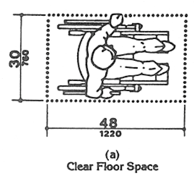
Fig. 4 Minimum Clear Floor Space for Wheelchairs
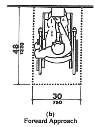
Fig. 4 Minimum Clear Floor Space for Wheelchairs
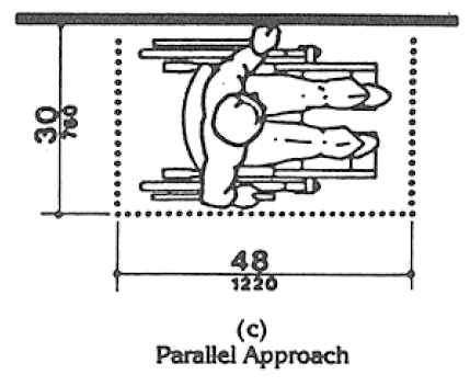
Fig. 4 Minimum Clear Floor Space for Wheelchairs
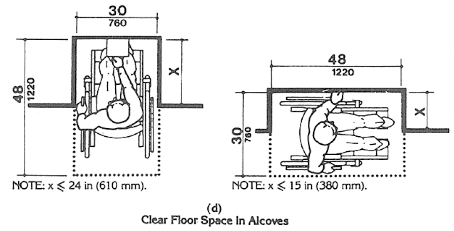
Fig. 4 Minimum Clear Floor Space for Wheelchairs
Fig. 4 Minimum Clear Floor Space for Wheelchairs
(d) Doors:
(i) Where it is technically infeasible to comply with clear opening width requirements of 4.13.5, a projection of 5/8 in maximum will be permitted for the latch side stop.
(ii) If existing thresholds are 3/4 in high or less, and have (or are modified to have) a beveled edge on each side, they may remain.
(e) Toilet Rooms:
(i) Where it is technically infeasible to comply with 4.22 or 4.23, the installation of at least one unisex toilet/bathroom per floor, located in the same area as existing toilet facilities, will be permitted in lieu of modifying existing toilet facilities to be accessible. Each unisex toilet room shall contain one water closet complying with 4.16 and one lavatory complying with 4.19, and the door shall have a privacy latch.
(ii) Where it is technically infeasible to install a required standard stall (Fig. 30(a)), or where other codes prohibit reduction of the fixture count (i.e., removal of a water closet in order to create a double-wide stall), either alternate stall (Fig.30(b)) may be provided in lieu of the standard stall.
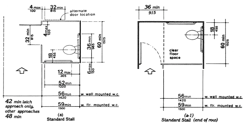
Fig. 30 Toilet Stalls
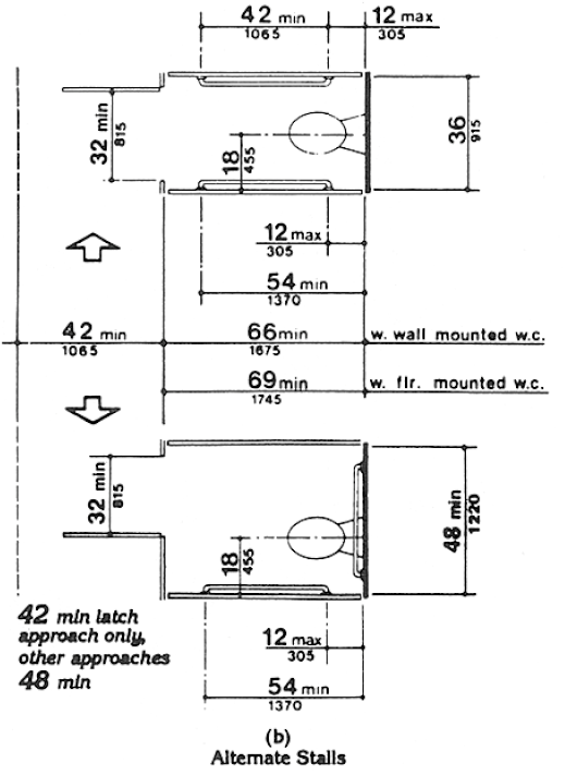
Fig. 30 Toilet Stalls
(iii) When existing toilet or bathing facilities are being altered and are not made accessible, signage complying with 4.30.1, 4.30.2, 4.30.3, 4.30.5, and 4.30.7 shall be provided indicating the location of the nearest accessible toilet or bathing facility within the facility.
(f) Assembly Areas:
(i) Where it is technically infeasible to disperse accessible seating throughout an altered assembly area, accessible seating areas may be clustered. Each accessible seating area shall have provisions for companion seating and shall be located on an accessible route that also serves as a means of emergency egress.
(ii) Where it is technically infeasible to alter all performing areas to be on an accessible route, at least one of each type of performing area shall be made accessible.
(g) Platform Lifts (Wheelchair Lifts): In alterations, platform lifts (wheelchair lifts) complying with 4.11 and applicable state or local codes may be used as part of an accessible route. The use of lifts is not limited to the four conditions in exception 4 of 4.1.3(5).
(h) Dressing Rooms: In alterations where technical infeasibility can be demonstrated, one dressing room for each sex on each level shall be made accessible. Where only unisex dressing rooms are provided, accessible unisex dressing rooms may be used to fulfill this requirement.
User Comments/Questions
Add Comment/Question