Doors, Doorways and Gates [§206.5 and §404]
Compliance is required for doors, doorways, and gates providing user passage on accessible routes. At least one accessible door, doorway, or gate serving each accessible room, space, and entrance must comply.
Manual Doors and Gates [§404.2]
Clear With [sic] [§404.2.3]
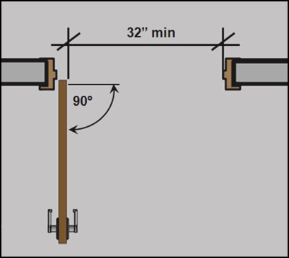
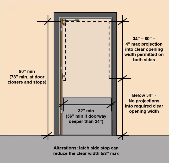
The clear width is measured from the stop to the face of doors or gates open 90⁰ (or to the leading edge of sliding or folding doors. No projection into the clear width is permitted below 34.”
Clear Width and Vertical Clearance of Doors and Gates [§404.2.3]
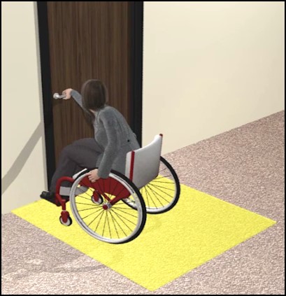
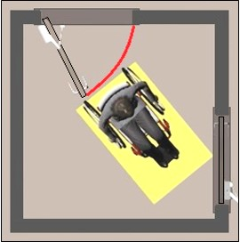
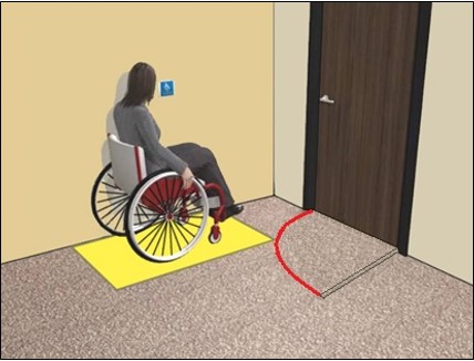
Maneuvering Clearances [§404.2.4]
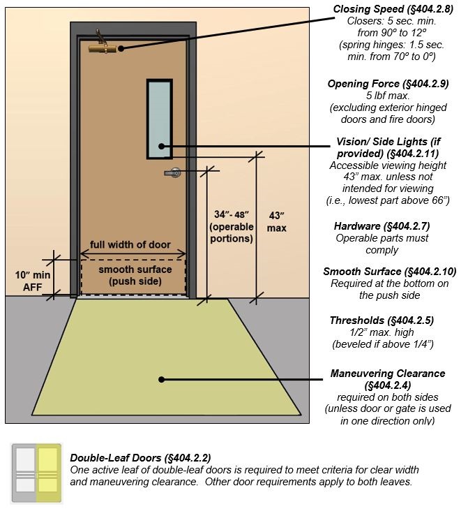
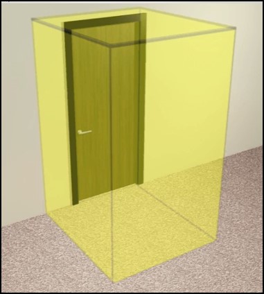
Required maneuvering clearances provide space for opening and proceeding through doors, doorways, and gates using wheelchairs and other mobility aids.
Required door clearances provide unobstructed space for maneuvering through doorways.
Maneuvering clearances must be free of protrusions the full height (80” min.) and changes in level (other than thresholds).
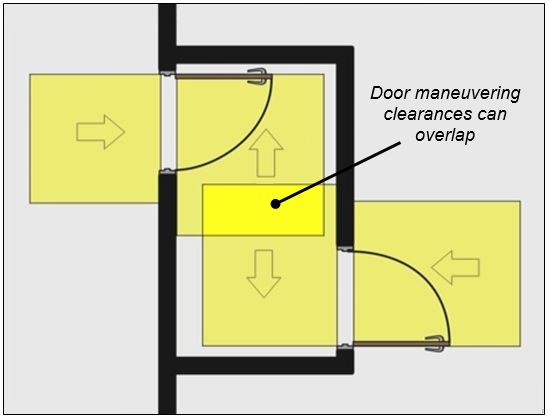
Maneuvering clearances are specified according to direction of approach, swing of doors, and in some cases the presence of a closer or latch. They are required on both sides of doors or gates except at those that can be used in one direction only.

Clearance beyond the latch side is not required at entry doors to hospital patient rooms. Such doors are usually wider to accommodate beds and gurneys, and they are often located close to adjacent interior walls to facilitate circulation and to enhance privacy.
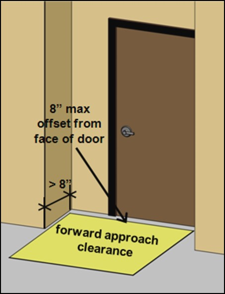
Recessed Doors and Gates [§404.2.4.3]
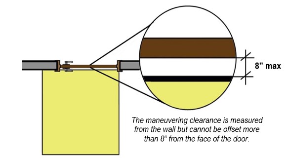
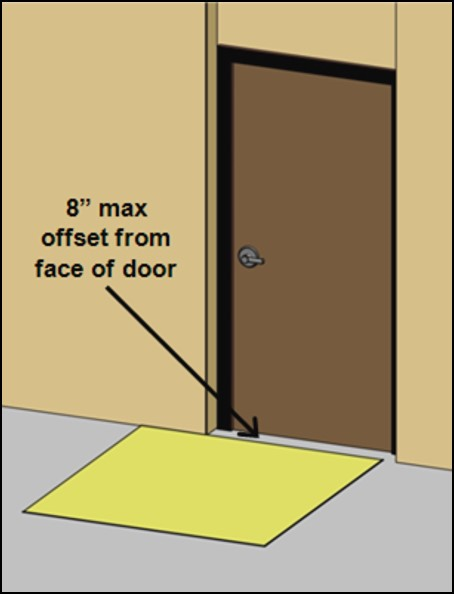
Thick walls, casework, shelving, columns and other elements can cause doors or gates to be recessed. If any obstruction within 18” of the latch side projects more than 8” from the face of a door or gate, maneuvering clearances for a forward approach must be provided. This space must be inset at obstructions so that it is no more than 8” from the face of the door or gate.
Walls and other obstructions can offset the maneuvering clearance up to 8” from the face of the door.
At deeper recesses, the maneuvering clearance must be sized for a forward approach and located 8” maximum from the face of the door.
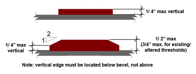
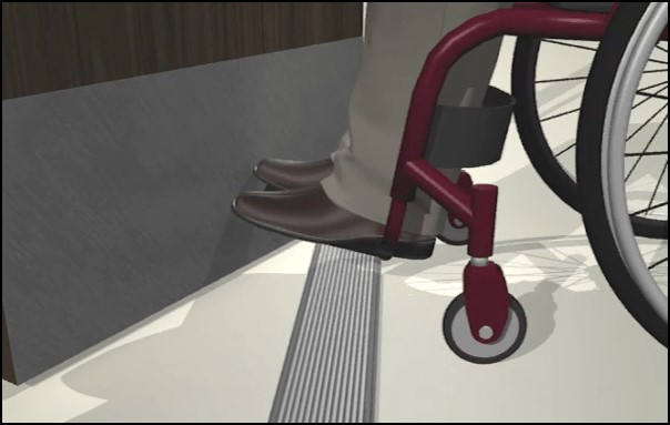
Thresholds [§404.2.5]
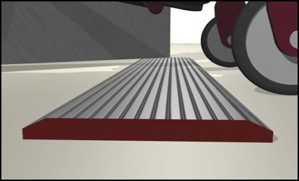
The height of thresholds is limited to 1/2” in new construction. The edge must be beveled 1:2 maximum above a height of 1/4”. A maximum height of 3/4” is permitted for existing or altered thresholds if they have a beveled edge on each side with a slope not steeper than 1:2. These requirements apply to all types of doors required to comply, including sliding doors.
Threshold Profile
Doors and Gates in Series [§404.2.6]
At hinged or pivoted doors or gates in series, a separation is required that is at least 48” plus the width of doors or gates swinging into the space. This allows users to clear one door or gate before opening the next and applies to those doors or gates that are opposite each other where travel through both doors is required.
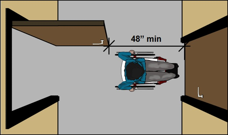

Recommendation: Wheelchair space 30” min. by 48” min. beyond the swing of a door in other configurations, such as vestibules with doors on adjacent walls, will provide room to clear one door before opening the next.
Door and Gate Hardware [§404.2.7]
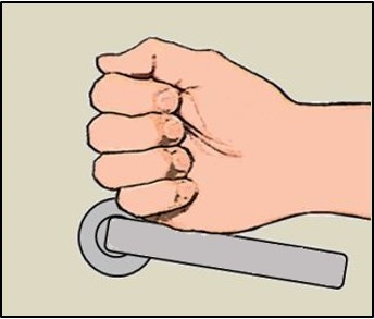
Door and gate hardware must:
-
allow one-hand operation
-
not require tight grasping, pinching, or twisting of the wrist
-
operate with 5 lbf maximum
-
be located 34” to 48” above the floor or ground.
Hardware that can be operated with a loose grip or closed fist, such as lever-shaped handles and U-shaped pulls, accommodates the greatest range of users. (Closed-fist operation, while advisable, is not mandated by the Standards). Round door knobs do not comply because they require twisting of the wrist.
Latches and locks with small parts that must be manipulated can be difficult to use and will not comply if pinching is necessary. However, keys and access cards that are not part of the lockset are not required to comply (but those that do not require pinching or turning provide better access). Hardware that does not require simultaneous actions are better, but some types, such as handles with thumb latches are acceptable.

Recommendations:
-
Specify hardware that is usable with a closed fist of loose grip
-
Bars, pulls, and similar hardware should provide sufficient knuckle clearance (1½” minimum) to facilitate gripping
-
Avoid hardware that requires hand or finger dexterity, fine motor movement, or simultaneous actions.
Opening Force [§404.2.9]
The maximum 5 lbf opening force applies to all accessible doors and gates except:
-
fire doors (minimum opening force allowed by code)
-
exterior hinged doors (no maximum specified)
-
latch bolts and other devices that keep doors or gates closed
The 5 lbf maximum applies to the continuous application of force necessary to fully open a door, not the initial force needed to overcome the door’s seal resulting from unequal pressure. Latch bolts must be retracted and other devices that keep doors or gates closed must be disengaged prior to measuring the opening force. (Such devices, like other door and gate hardware, must operate with a maximum 5 lbf force (§404.2.7), but their operating force is not included in the measure of door or gate opening force). Door pressure gauges and other products are available to measure the opening force.
Measuring Door or Gate Opening Force with Pressure Gauge
When using door gauges and other measuring devices, it is advisable to follow these steps (except where product instructions specify otherwise):
-
Open the door so that the face edge aligns with the door frame outside edge
-
Place gauge immediately above door operating hardware about 2½” from the latch edge of the door (approximately the centerline of the door hardware)
-
Push slowly keeping the pressure gauge perpendicular to the face of the door
-
Remove the pressure gauge when the door is open 70 degrees.
Opening Force of Exterior Doors
The opening force of exterior swing doors is impacted by wind loading and other exterior conditions, gasketing, HVAC systems, energy efficiency, and the weight of doors. The minimum force needed to ensure proper closure and positive latch usually exceeds the accessible limit of 5 pounds of force (lbf) required at other doors. For this reason, a maximum opening force is not specified for exterior hinged doors.

Recommendation: Automation of exterior doors is recommended, especially where the opening force is likely to be significant. Otherwise, closers should be calibrated with the least force necessary for closure to minimize the opening force. Difficulty opening manual entrance doors is a common access complaint.
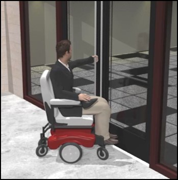
Door and Gate Surfaces [§404.2.10]
The bottom surface of doors and gates on the push side must be smooth to a height of at least 10”. This facilitates access since mobility aids, including wheelchair footrests, are sometimes used to push or prop open doors. Kick plates can be used to help protect door surfaces, but any gaps or cavities between the kick plate and the door surface must be closed or capped. Horizontal or vertical joints in this surface cannot exceed a 1/16” variation in plane.
These requirements do not apply to:
-
Sliding doors
-
Doors and gates that do not extend to within 10” of the finish floor or ground
-
Existing doors or gates with kick plates (so long as cavities created by kick plates are capped)
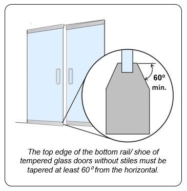
-
Tempered glass doors without stiles if the top edge of the bottom rail or shoe is tapered at least 60⁰ from the horizontal.
Communication Access at Doors [§806.3.2, §806.3.2]
ETA Editor's Note
This section title contains a typo, as it duplicates section number "806.3.2." On the Access Board's website, however, the second "806.3.2" is actually hyperlinked to the correct section, 809.5.5, regarding primary entrances in residential dwelling units.
In addition to requirements for two-way communication systems provided at restricted entrances, the Standards include requirements for communication access in transient lodging and residential facilities:

-
visible signals for door bells or knocks are required in transient lodging guest rooms providing communication access (§806.3.2);
-
a hard-wired doorbell with visible signals is required at the primary entrance in dwelling units providing communication access, along with a means to visually identify visitors without opening the door, such as a vision panel or peephole (§809.5.5).

Recommendation: Peepholes and other means of identifying visitors in mobility accessible guest rooms and dwelling units are not addressed by the Standards. Products are available with prisms and optical lenses that do not require a close approach and can be easily used from standing and seated postures. They are more effective than locating a regular peephole at a lower height which can impact visual identification of visitors.
Doors and Gates Operated Only By Security Personnel [§404.1, Ex]

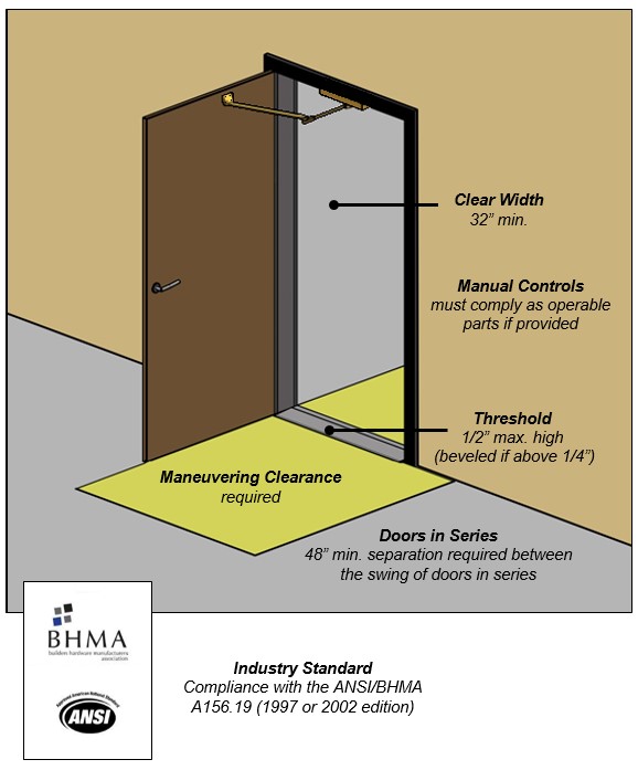
Manual doors, doorways, and gates that are designed to be operated only by security personnel, such as guards in a jail or prison, are exempt from requirements for hardware, closing speed, and opening force, but must meet all other requirements, including those for maneuvering clearance. This exception applies only where security personnel have sole control of doors or gates. If automated, such doors or gates are required to comply only with provisions for clear width and thresholds, as well as applicable provisions of the referenced ANSI/BHMA Standards.
Automatic and Power-Assisted Doors and Gates [§404.3]

Doors are not required to be automated, but must comply when provided. The Standards apply industry Standards developed under protocols of the American National Standards Institute (ANSI) and published by the Builders Hardware Manufacturers Association (BHMA). The ANSI/BHMA Standards address operating characteristics, including opening speed, safety features, sensors and activation devices, and labeling, among others. Doors are classified by their type or level of automation.
Power-Assisted Doors and Gates [§404.3]
Power-assisted devices reduce the opening force of doors with closing mechanisms.
They are activated by initial manual force, switches, or sensors. Most reduce, but do not fully eliminate, the manual force needed to open a door. For this reason, they must meet maneuvering clearance requirements.
Power-Assisted Door
Low Energy Doors and Gates [§404.3]
Low energy doors and gates usually require activation by the user through a push plate or control and are often used in moderate traffic locations as an alternative to manual operation. Most function like a manual type but with a powered opener and closer option.
Automated Door (Low Energy)
Controls [§404.3.5]
Door and gate controls must be compliant as operable parts (operable with one hand and without tight grasping, pinching, twisting of the wrist, or more than 5 lbf). Clear floor space at controls must be located outside the door swing to prevent users from getting hit by the door.
Clear floor space at door control must be located outside door swing.
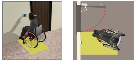

Recommendation: Placing controls in locations that preclude backing-up will facilitate usability. The clear floor space is not required to be centered at controls, but should be located to facilitate reach and operation.
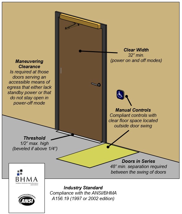
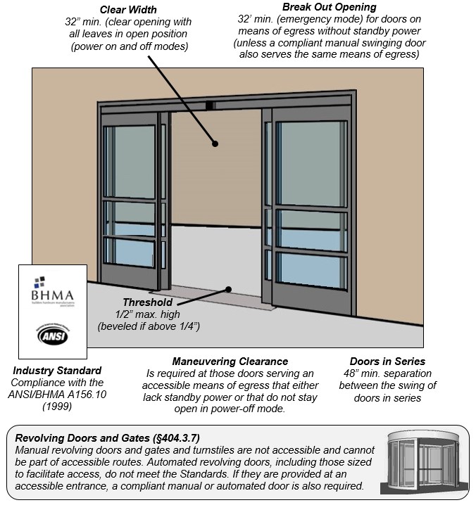
Full-Powered Automatic Doors and Gates [§404.3]
Full-powered automatic doors and gates are often found in grocery and retail stores, hotels, and airports to ease passage with shopping carts or luggage. Most are automatically activated by mats or overhead sensors and do not require manual activation by users.
Automated Door (Full-Powered)
User Comments/Questions
Add Comment/Question